CN219252884U - Building rubbish classification equipment - Google Patents
Building rubbish classification equipment Download PDFInfo
- Publication number
- CN219252884U CN219252884U CN202223180615.6U CN202223180615U CN219252884U CN 219252884 U CN219252884 U CN 219252884U CN 202223180615 U CN202223180615 U CN 202223180615U CN 219252884 U CN219252884 U CN 219252884U
- Authority
- CN
- China
- Prior art keywords
- box
- waste
- classification
- wall
- motor
- Prior art date
- Legal status (The legal status is an assumption and is not a legal conclusion. Google has not performed a legal analysis and makes no representation as to the accuracy of the status listed.)
- Active
Links
Images
Classifications
-
- Y—GENERAL TAGGING OF NEW TECHNOLOGICAL DEVELOPMENTS; GENERAL TAGGING OF CROSS-SECTIONAL TECHNOLOGIES SPANNING OVER SEVERAL SECTIONS OF THE IPC; TECHNICAL SUBJECTS COVERED BY FORMER USPC CROSS-REFERENCE ART COLLECTIONS [XRACs] AND DIGESTS
- Y02—TECHNOLOGIES OR APPLICATIONS FOR MITIGATION OR ADAPTATION AGAINST CLIMATE CHANGE
- Y02W—CLIMATE CHANGE MITIGATION TECHNOLOGIES RELATED TO WASTEWATER TREATMENT OR WASTE MANAGEMENT
- Y02W30/00—Technologies for solid waste management
- Y02W30/50—Reuse, recycling or recovery technologies
- Y02W30/58—Construction or demolition [C&D] waste
Abstract
The utility model relates to the technical field of garbage classification treatment, and particularly discloses construction garbage classification treatment equipment, wherein a water receiving mechanism for collecting wastewater is arranged in a shell, a crushing mechanism is arranged on the left side of the water receiving mechanism, and an adsorption mechanism for adsorbing iron in waste is arranged in a classification box; this building rubbish classification equipment, motor two drive electromagnetic block stretches into the part transfer lever of classifying box at the processing box and carries out horizontal reciprocating motion, transfer lever drives the waste material simultaneously and rotates, both are in dynamic motion balance, thereby adsorb the iron metal on the transfer lever and in the waste material, after the absorption is accomplished, the motor reversal drives the movable block and reverse removal to the assigned position after, outage to the electromagnetic block, the iron metal is automatic to drop, can accomplish the collection to the iron metal in the waste material, not only efficient, moreover degree of automation is higher, the adsorption effect of iron metal has been increased.
Description
Technical Field
The utility model relates to the technical field of garbage classification treatment, in particular to construction garbage classification treatment equipment.
Background
The construction waste refers to dregs, waste soil, waste materials, waste mud and other wastes generated in the process of constructing, laying or dismantling various buildings, structures, pipe networks and the like of construction units or personal teams. At present, the quantity of the construction wastes in China already occupies the main component of the urban wastes. However, most of the construction waste is transported to suburbs or villages by construction units without any treatment, and is piled up or buried in open air, so that a large amount of construction expenses such as land fees, garbage cleaning and transporting fees are consumed, and meanwhile, the problems of scattering, dust, ash and sand flying and the like in the process of cleaning and piling up are caused to seriously pollute the environment.
When the existing construction waste classification treatment device is used for treating construction waste, the construction waste is generally crushed, crushed ferrous metals and solid waste are uniformly mixed together, then the iron metals in the mixed waste are adsorbed and separated by adopting a magnet, and separation of ferrous resources in the waste and recycling of the ferrous metals are completed.
After the construction waste is crushed, ferrous metal and waste are mixed and placed together, when the magnet adsorbs the metal, part of the metal in the waste can be pressed at the bottom by the mixture fixed by stacking, or the magnet is blocked by objects in the waste, so that the magnet cannot adsorb the ferrous metal, the phenomenon of leakage attraction of the metal occurs, and the waste of metal resources is caused.
Disclosure of Invention
The utility model aims to provide a construction waste classification treatment device which solves the following technical problems:
how to recycle the leaked ferrous metal in the construction waste.
The aim of the utility model can be achieved by the following technical scheme:
the utility model provides a building rubbish classification equipment, includes the casing, one side fixed mounting of casing has the classification case, the bottom of casing and classification case is fixed mounting all around has the supporting leg, the top surface fixed mounting of casing has the feed inlet, its characterized in that, the inside of casing sets up the receipts water mechanism that is used for collecting waste water, one side of receipts water mechanism is provided with the crushing mechanism that is used for smashing the waste material after the waste water treatment is accomplished, the below of crushing mechanism is provided with the conveying mechanism that is used for conveying the crushed material, the inside of classification case is provided with the adsorption mechanism that is used for adsorbing iron in the waste material;
the adsorption mechanism comprises an electromagnetic block and a driving assembly, and the electromagnetic block horizontally reciprocates under the action of the driving force of the driving assembly.
Further, adsorption equipment is including fixing the motor II on the interior roof of classifying box, the output fixed mounting of motor II has the threaded rod, the surface threaded connection of threaded rod has the movable block, sliding connection has the slide bar to run through in the left and right sides of movable block, the bottom of movable block and the top fixed mounting of electromagnetism piece, the stopper on classifying box inner roof is all fixedly connected with at the surface at slide bar both ends, the one end that the motor II was kept away from to the threaded rod rotates with the inner wall of stopper to be connected.
Further, the water collecting mechanism comprises a water collecting tank, a drainage plate is fixedly installed on the inner wall of the right side of the shell, a plurality of holes are formed in the surface of the drainage plate in a penetrating mode up and down, water retaining plates are fixedly installed on two sides of the top surface of the drainage plate, a fixing plate which is in sliding connection with the bottom of the water collecting tank is fixedly installed on the inner wall of the right side of the shell, the drainage plate is obliquely arranged with a downward opening, and the right side of the shell is provided with an opening which is matched with the size of the water collecting tank.
Further, the pressing mechanism comprises a first motor fixedly installed at the top of the classifying box, a driving shaft penetrating through one side of the shell and extending to the inside is fixedly installed at the output end of the first motor, a driven shaft is rotatably connected with the driving shaft through a gear set, and the outer surfaces of the driving shaft and the driven shaft are rotatably connected with one side, close to the first motor, of the shell.
Further, the conveying mechanism comprises a processing box fixedly installed on the inner wall of one side of the shell, the inner wall of the processing box is rotationally connected with a conveying rod extending to the outside through the inner wall of one side, the outer surface of the conveying rod and the outer surface of the driving shaft are fixedly provided with driving wheels, and the driving wheels are in transmission connection through a belt.
Further, the bottom of classifying box is provided with the compression mechanism who is used for compressing construction waste, the interior bottom wall fixed mounting of classifying box has the compression case, the right side inner wall fixed mounting of compression case has the compression cylinder, the output fixed mounting of compression cylinder is with the compression board that the compression case inner wall size is the same, the stripper is installed in the left side bottom rotation of compression case, the bottom of classifying box has run through and has been offered the opening of being convenient for iron and waste material transportation that drops, the bottom of stripper and the waste material opening fixed mounting of classifying box have the spring.
Further, the bottom of the processing box is penetrated and provided with a notch which is convenient for transporting waste, and the distance between the notch and the processing box is far longer than the length of the stripper plate.
The utility model has the beneficial effects that:
(1) According to the utility model, the threaded rod is driven by the motor to rotate, the threaded rod drives the moving block to rotate, meanwhile, the sliding rod horizontally limits the moving block, so that the moving block horizontally moves, the electromagnetic block is driven by the moving block to horizontally move, the electromagnetic block is electrified to generate magnetic force to adsorb iron metal in crushed waste, the second motor drives the electromagnetic block to horizontally reciprocate on a part of the conveying rod of the treatment box extending into the classification box, and meanwhile, the conveying rod drives the waste to rotate, and the two parts are in dynamic motion balance, so that iron metal on the conveying rod and in the waste is adsorbed. After the adsorption is completed, the motor is reversely rotated to drive the movable block to horizontally move to the designated position, the electromagnetic block is powered off, the ferrous metal automatically falls off, the collection of the ferrous metal in the waste is completed, the efficiency is high, the automation degree is high, the adsorption effect of the ferrous metal is improved, and the leakage of the ferrous metal in the waste is reduced.
Drawings
The utility model is further described below with reference to the accompanying drawings.
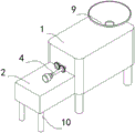
FIG. 1 is a schematic view of the overall structure of the present utility model;
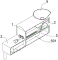
FIG. 2 is a cross-sectional view of the overall structure of the present utility model;
FIG. 3 is a top view of the water receiving mechanism of the present utility model;
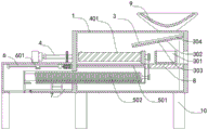
FIG. 4 is an overall front cross-sectional view of the present utility model;
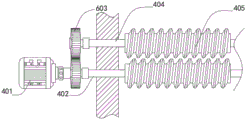
FIG. 5 is a top view of the adsorption mechanism of the present utility model;
fig. 6 is a front view of the compression mechanism of the present utility model.
Reference numerals: 1. a housing; 2. a classification box; 3. a water receiving mechanism; 301. a water collection tank; 302. a drainage plate; 303. a hole; 304. a water baffle; 4. a crushing and grinding mechanism; 401. a first motor; 402. a driving shaft; 403. a gear set; 404. a driven shaft; 405. a pulverizing wheel; 5. a conveying mechanism; 501. a treatment box; 502. a transfer lever; 6. an adsorption mechanism; 601. an electromagnetic block; 602. a second motor; 603. a threaded rod; 604. a moving block; 605. a slide bar; 606. a limiting block; 7. a compression mechanism; 701. a compression box; 702. a compression cylinder; 703. a compression plate; 704. a stripper plate; 8. a fixing plate; 9. a feed inlet; 10. and (5) supporting legs.
Detailed Description
The following description of the embodiments of the present utility model will be made clearly and completely with reference to the accompanying drawings, in which it is apparent that the embodiments described are only some embodiments of the present utility model, but not all embodiments. All other embodiments, which can be made by those skilled in the art based on the embodiments of the utility model without making any inventive effort, are intended to be within the scope of the utility model.
Referring to fig. 1-6, a sorting box 2 is fixedly installed on the right side of a shell 1, supporting legs 10 are fixedly installed around the bottoms of the shell 1 and the sorting box 2, a feeding port 9 is fixedly installed on the top surface of the shell 1, a water collecting mechanism 3 for collecting waste water is arranged in the shell 1, the water collecting mechanism 3 comprises a water collecting tank 301, a drainage plate 302 is fixedly installed on the inner wall of the right side of the shell 1, a plurality of holes 303 are formed in the surface of the drainage plate 302 in a penetrating mode up and down, water baffle plates 304 are fixedly installed on two sides of the top surface of the drainage plate 302, a fixing plate 8 which is in sliding connection with the bottom of the water collecting tank 301 is fixedly installed on the inner wall of the right side of the shell 1, the drainage plate 302 is obliquely arranged with a downward opening, and an opening matched with the size of the water collecting tank 301 is formed in the right side of the shell 1.
One side of the water receiving mechanism 3 is provided with a crushing mechanism 4 for crushing waste materials after wastewater treatment is completed, the crushing mechanism 4 comprises a first motor 401 fixedly installed at the top of the classifying box 2, the output end of the first motor 401 is fixedly provided with a driving shaft 402 penetrating through one side of the shell 1 and extending to the inside, the driving shaft 402 is rotationally connected with a driven shaft 404 through a gear set 403, and the outer surfaces of the driving shaft 402 and the driven shaft 404 are rotationally connected with one side, close to the first motor 401, of the shell 1. The conveying mechanism 5 for conveying crushed materials is arranged below the crushing mechanism 4, the conveying mechanism 5 comprises a processing box 501 fixedly arranged on the inner wall of one side of the shell 1, the inner wall of the processing box 501 is rotationally connected with a conveying rod 502 extending to the outside through the inner wall of one side, the outer surface of the conveying rod 502 and the outer surface of the driving shaft 402 are fixedly provided with driving wheels, and the driving wheels are connected through belt transmission.
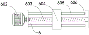
The adsorption mechanism 6 comprises a second motor 602 fixed on the inner top wall of the classifying box 2, a threaded rod 603 is fixedly arranged at the output end of the second motor 602, a moving block 604 is connected to the surface of the threaded rod 603 in a threaded manner, sliding rods 605 are connected to the left side and the right side of the moving block 604 in a penetrating and sliding manner, the bottoms of the moving block 604 and the tops of the electromagnetic blocks 601 are fixedly arranged, limiting blocks 606 fixed on the inner top wall of the classifying box 2 are fixedly connected to the outer surfaces of the two ends of the sliding rods 605, and one end, far away from the second motor 602, of the threaded rod 603 is connected with the inner wall of the limiting blocks 606 in a rotating manner. The second motor 602 drives the threaded rod 603 to rotate, and meanwhile the sliding rod 605 horizontally limits the moving block 604, so that the moving block 604 drives the electromagnetic block 601 to reciprocate on the surface of the sliding rod 605, the electromagnetic block is electrified to generate magnetic force to adsorb iron metal in crushed waste, and meanwhile the second motor 602 drives the electromagnetic block 601 to reciprocate on the part of the conveying rod 502 of the treatment box 501 extending into the classification box, so that part of iron metal clamped on the conveying rod 502 is adsorbed. After the adsorption is finished, the second motor reversely rotates to drive the moving block to reversely move to the designated position, and the electromagnetic block is powered off to finish the collection and treatment of ferrous metals in the waste, so that the efficiency is high, the automation degree is high, and the recovery is convenient.
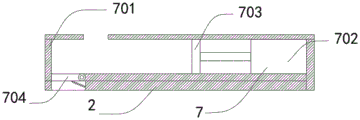
The bottom of classifying box 2 is provided with the compressing mechanism 7 that is used for compressing construction waste, the interior bottom wall fixed mounting of classifying box 2 has compression box 701, the right side inner wall fixed mounting of compression box 701 has compression cylinder 702, compression cylinder 702's output fixed mounting and compression box 701 inner wall big or small the same compression board 703, the stripper 704 is installed in the left side bottom rotation of compression box 701, the opening that is convenient for iron and waste drop transportation has been run through to classifying box 2's bottom, the bottom of stripper 704 and classifying box 2's waste material opening fixed mounting have the spring. The bottom of the treatment tank 501 is provided with a notch in a penetrating way, which is convenient for transporting waste, and the distance between the notch and the treatment tank 501 is far longer than the length of the stripper plate 704. Compression of the waste is completed by driving the compression plate 703 to move through the compression cylinder 702 and attaching the compression box 701, meanwhile, the compressed waste is opened at the discharge plate 704 due to the dead weight of the waste, and after the waste is transported, the discharge plate 704 is reset under the action of spring force. Thus, the compression transportation treatment of the waste materials is automatically completed, and the working efficiency is improved.
The first motor 401 and the second motor 602 are electrically connected to an external power source, and the second motor 602 can rotate positively and negatively. The oil inlet of the compression cylinder 702 communicates with the oil outlet of the external oil pump.
Working principle: when the device is used, waste is sent into a feed port 9, under the action of the dead weight of the waste, the waste falls into a treatment box 501 along the inclined surface of a drainage plate 302, a motor I401 drives a driving shaft 402 to rotate, a driving shaft 402 and a driven shaft 404 drive a crushing wheel 405 to rotate through a gear set 403, the driving shaft 402 and a belt drive a transmission rod 502 to rotate, a motor II 602 drives a threaded rod 603 to rotate, the threaded rod 603 drives a moving block 604 to rotate, meanwhile, a sliding rod 605 horizontally limits the moving block 604, so that the moving block 604 horizontally moves on the outer surface of the sliding rod 605, the moving block 604 drives an electromagnetic block 601 to reciprocate, the electromagnetic block 601 is electrified to generate magnetic force to adsorb iron metal in crushed waste, the motor II 602 is reversely rotated to drive the moving block 604 to reversely move, and the electromagnetic block 601 is subjected to power-off treatment after the specified position is reached; under the action of rotation of the conveying rod 502, the waste material after iron metal adsorption is removed moves to fall into the compression box 701 through the opening of the treatment box 501, the compression cylinder 702 is started to drive the compression plate 703 to horizontally move and extrude the waste, the compression box 701 is rotationally connected with the stripper plate 704, a spring is arranged between the stripper plate 704 and the compression box 701, after the waste is compressed into blocks, the weight is concentrated on the stripper plate 704, so that the stripper plate 704 rotates to be opened, the spring is compressed, and after the waste falls out, the stripper plate 704 is closed under the action of the spring.
The foregoing describes one embodiment of the present utility model in detail, but the description is only a preferred embodiment of the present utility model and should not be construed as limiting the scope of the utility model. All equivalent changes and modifications within the scope of the present utility model are intended to be covered by the present utility model.
Claims (7)
1. The utility model provides a building rubbish classification equipment, includes casing (1), one side fixed mounting of casing (1) has classification case (2), the bottom of casing (1) and classification case (2) is fixed mounting all around has supporting leg (10), the top surface fixed mounting of casing (1) has feed inlet (9), a serial communication port, the inside of casing (1) sets up receipts water mechanism (3) that are used for collecting waste water, one side of receipts water mechanism (3) is provided with and is used for carrying out kibbling crushing mechanism (4) to waste material after the waste water treatment is accomplished, the below of crushing mechanism (4) is provided with conveying mechanism (5) that are used for conveying the crushing material, the inside of classification case (2) is provided with adsorption mechanism (6) that are used for adsorbing iron in the waste material;
the adsorption mechanism (6) comprises an electromagnetic block (601) and a driving assembly, and the electromagnetic block (601) horizontally reciprocates under the action of driving force of the driving assembly.
2. The building rubbish classification equipment according to claim 1, wherein the adsorption mechanism (6) comprises a second motor (602) fixed on the inner top wall of the classification box (2), a threaded rod (603) is fixedly arranged at the output end of the second motor (602), a moving block (604) is connected to the surface of the threaded rod (603) in a threaded manner, sliding rods (605) are connected to the left side and the right side of the moving block (604) in a penetrating and sliding manner, the bottoms of the moving block (604) are fixedly arranged at the tops of the electromagnetic blocks (601), limiting blocks (606) fixed on the inner top wall of the classification box (2) are fixedly connected to the outer surfaces of the two ends of the sliding rods (605), and one end, far away from the second motor (602), of the threaded rod (603) is rotationally connected with the inner wall of each limiting block (606).
3. The building waste classification equipment according to claim 1, wherein the water collecting mechanism (3) comprises a water collecting tank (301), a drainage plate (302) is fixedly installed on the inner wall of the right side of the shell (1), a plurality of holes (303) are formed in the surface of the drainage plate (302) in a penetrating mode, water retaining plates (304) are fixedly installed on two sides of the top surface of the drainage plate (302), a fixing plate (8) which is in sliding connection with the bottom of the water collecting tank (301) is fixedly installed on the inner wall of the right side of the shell (1), the drainage plate (302) is obliquely arranged with a downward opening, and the right side of the shell (1) is provided with an opening which is matched with the size of the water collecting tank (301).
4. A construction waste classification apparatus according to claim 3, wherein the crushing mechanism (4) comprises a first motor (401) fixedly installed at the top of the classification box (2), a driving shaft (402) penetrating one side of the housing (1) and extending to the inside is fixedly installed at the output end of the first motor (401), the driving shaft (402) is rotatably connected with a driven shaft (404) through a gear set (403), and the outer surfaces of the driving shaft (402) and the driven shaft (404) are rotatably connected with one side of the housing (1) close to the first motor (401).
5. The construction waste classification processing apparatus according to claim 4, wherein the conveying mechanism (5) comprises a processing box (501) fixedly installed on an inner wall of one side of the housing (1), a conveying rod (502) extending to the outside through the inner wall of one side is rotatably connected to the inner wall of the processing box (501), and driving wheels are fixedly installed on the outer surfaces of the conveying rod (502) and the driving shaft (402), and are connected through belt transmission.
6. The construction waste classification processing device according to claim 5, wherein a compression mechanism (7) for compressing construction waste is arranged at the bottom of the classification box (2), a compression box (701) is fixedly arranged on the inner bottom wall of the classification box (2), a compression cylinder (702) is fixedly arranged on the right inner wall of the compression box (701), a compression plate (703) with the same size as the inner wall of the compression box (701) is fixedly arranged at the output end of the compression cylinder (702), a discharge plate (704) is rotatably arranged at the left bottom of the compression box (701), an opening for facilitating falling and transportation of iron and waste is formed in the bottom of the classification box (2), and a spring is fixedly arranged at the bottom of the discharge plate (704) and the waste opening of the classification box (2).
7. The construction waste sorting and processing apparatus according to claim 6, wherein the bottom of the processing box (501) is provided with a slot through which waste is transported, the distance between the slot and the processing box (501) being substantially longer than the length of the stripper plate (704).
Priority Applications (1)
| Application Number | Priority Date | Filing Date | Title |
|---|---|---|---|
| CN202223180615.6U CN219252884U (en) | 2022-11-28 | 2022-11-28 | Building rubbish classification equipment |
Applications Claiming Priority (1)
| Application Number | Priority Date | Filing Date | Title |
|---|---|---|---|
| CN202223180615.6U CN219252884U (en) | 2022-11-28 | 2022-11-28 | Building rubbish classification equipment |
Publications (1)
| Publication Number | Publication Date |
|---|---|
| CN219252884U true CN219252884U (en) | 2023-06-27 |
Family
ID=86857393
Family Applications (1)
| Application Number | Title | Priority Date | Filing Date |
|---|---|---|---|
| CN202223180615.6U Active CN219252884U (en) | 2022-11-28 | 2022-11-28 | Building rubbish classification equipment |
Country Status (1)
| Country | Link |
|---|---|
| CN (1) | CN219252884U (en) |
-
2022
- 2022-11-28 CN CN202223180615.6U patent/CN219252884U/en active Active
Similar Documents
| Publication | Publication Date | Title |
|---|---|---|
| CN208177648U (en) | A kind of building waste separation recoverer with environment-friendly function | |
| CN108906201B (en) | Waste material reducing mechanism for building engineering of environmental protection | |
| CN109158152B (en) | Building rubbish fine crushing and screening device | |
| CN109900107B (en) | Movable construction waste recycling device and using method | |
| CN107876162A (en) | A kind of solid waste crushes multistage recycling and processing device | |
| CN111841715B (en) | Building rubbish classification device | |
| CN111495487A (en) | Novel building rubbish system sand equipment | |
| CN108745585A (en) | A kind of waste and old brick and tile high-efficient treatment device | |
| CN112452415A (en) | Construction waste classification recovery processing device | |
| CN110694773B (en) | Civil engineering house building waste treatment device | |
| CN112474700A (en) | Production equipment and method for preparing recycled building material from building waste | |
| CN219252884U (en) | Building rubbish classification equipment | |
| CN112221584A (en) | Construction waste recycling device | |
| CN115155753B (en) | Screening device for recycling waste batteries | |
| CN116618151A (en) | Reinforced concrete waste classification reducing mechanism for building engineering | |
| CN111468222B (en) | Building rubbish is with categorised sieving mechanism | |
| CN210935367U (en) | Simple and easy increment device of dense medium ore dressing | |
| CN114082765A (en) | Equipment capable of sorting construction waste for multiple times based on environmental protection industry | |
| CN113814063A (en) | Magnetic separation device for industrial waste treatment | |
| CN209138730U (en) | A kind of building waste grinding device | |
| CN113894145A (en) | Civil engineering is with environment-friendly construction waste treatment facility | |
| CN209038325U (en) | A kind of novel building Waste sorting recycle utilizes equipment | |
| CN206868428U (en) | A kind of portable magnetic separator | |
| CN219849847U (en) | Broken splitter of building rubbish | |
| CN214515218U (en) | Building rubbish classification device |
Legal Events
| Date | Code | Title | Description |
|---|---|---|---|
| GR01 | Patent grant | ||
| GR01 | Patent grant |