CN219137524U - Central separation belt for collecting road drainage - Google Patents
Central separation belt for collecting road drainage Download PDFInfo
- Publication number
- CN219137524U CN219137524U CN202320210425.XU CN202320210425U CN219137524U CN 219137524 U CN219137524 U CN 219137524U CN 202320210425 U CN202320210425 U CN 202320210425U CN 219137524 U CN219137524 U CN 219137524U
- Authority
- CN
- China
- Prior art keywords
- water
- road
- holes
- collecting ditch
- planting soil
- Prior art date
- Legal status (The legal status is an assumption and is not a legal conclusion. Google has not performed a legal analysis and makes no representation as to the accuracy of the status listed.)
- Active
Links
Images

Classifications
-
- Y—GENERAL TAGGING OF NEW TECHNOLOGICAL DEVELOPMENTS; GENERAL TAGGING OF CROSS-SECTIONAL TECHNOLOGIES SPANNING OVER SEVERAL SECTIONS OF THE IPC; TECHNICAL SUBJECTS COVERED BY FORMER USPC CROSS-REFERENCE ART COLLECTIONS [XRACs] AND DIGESTS
- Y02—TECHNOLOGIES OR APPLICATIONS FOR MITIGATION OR ADAPTATION AGAINST CLIMATE CHANGE
- Y02A—TECHNOLOGIES FOR ADAPTATION TO CLIMATE CHANGE
- Y02A30/00—Adapting or protecting infrastructure or their operation
- Y02A30/60—Planning or developing urban green infrastructure
Landscapes
- Road Paving Structures (AREA)
Abstract
The utility model discloses a central separation belt for collecting road drainage, which comprises a water collecting ditch which is arranged along a road and positioned at the central line position of the road, wherein supporting bodies are fixed on the top surfaces of two sides of the water collecting ditch, a plurality of water passing holes are arranged on the supporting bodies at intervals along the length direction of the supporting bodies, the bottom ends of the water passing holes are lower than the road surface, a supporting plate with a through hole is supported between the two supporting bodies above the water passing holes, planting soil is covered on the supporting plate, green plants are planted in the planting soil, a plurality of water absorbing cotton ropes are buried in the planting soil at intervals, the other ends of the water absorbing cotton ropes penetrate through the through holes and extend into the inner bottom of the water collecting ditch, a plurality of water draining holes are arranged on the side walls of the water collecting ditch at intervals along the longitudinal direction of the road, a water draining pipe positioned under the road surface is connected to the water draining pipe, the other ends of the water draining pipe are connected with a local drainage system, and the road surface on two sides of the water collecting ditch inclines towards the water collecting ditch in the transverse direction; in arid and rainless seasons, the water is obtained from the water collecting ditch through the water absorbing cotton rope by green planting, manual watering is not needed, time and labor are saved, and the construction is simple.
Description
Technical Field
The utility model relates to a road central partition belt, in particular to a central partition belt for collecting road drainage.
Background
The existing road central separation belt is positioned at the center line of a road and is a banded facility for separating a roadway, which is longitudinally arranged along the road, generally comprises a road shoulder, a drainage blind pipe is longitudinally arranged along the road in an area surrounded by the road shoulder, gravel is paved above the drainage blind pipe in the area, planting soil is paved above the gravel, planting soil is planted in a green mode, a drain pipe capable of draining water to a local drainage system is connected to the drainage blind pipe, water in the central separation belt is drained to the local drainage system through the drainage blind pipe and the drain pipe, manual watering is needed for planting green plants in arid and rainless seasons, the road drainage system and the central separation belt are completely independent, independent construction is needed for the road drainage system and the central separation belt, construction is troublesome, time and labor are wasted, and cost is high.
Disclosure of Invention
In view of the above, the utility model aims to provide a central dividing strip for collecting road drainage, which solves the technical problems that the conventional central dividing strip is troublesome in greening and manual watering and the road drainage system and the central dividing strip are required to be independently constructed.
The utility model aims at realizing the following technical scheme:
the utility model provides a collect central dividing strip of road drainage, includes along the water catch bowl of road central line position that the road was arranged along the line, the top surface is fixed with the supporter all around, be equipped with a plurality of water holes along its length direction interval on the supporter, water hole bottom is less than the road surface, it has the backup pad of taking the through-hole to support between the supporter above the water hole, it has planting soil to cover in the backup pad, it has green planting to plant in the planting soil, plant soil interval buries a plurality of cotton ropes that absorb water, the cotton rope other end that absorbs water runs through the through-hole and stretches into the bottom in the water catch bowl, be equipped with a plurality of outlet along the road longitudinal separation on the water catch bowl lateral wall, be connected with the drain pipe that is located under the road surface on the outlet, the place drainage system is connected to the drain pipe other end, the road surface of water catch bowl both sides is in horizontal towards the water catch bowl slope.
Further, a reverse filter layer is laid under the planting soil on the supporting plate, and the water-absorbing cotton rope penetrates through the reverse filter layer.
Further, the reverse filtering layer is reverse filtering geotextile or gravel.
Further, the water inlet pipe is arranged in the water collecting ditch, the water inlet pipe is connected with the municipal water pipe through the electric control valve, the water level monitor is arranged in the water collecting ditch and is electrically connected with the controller, and the controller is electrically connected with the electric control valve.
Further, the support body is a reinforced concrete body.
Still further, the water passing hole is a vertically arranged long strip hole.
The beneficial effects of the utility model are as follows:
according to the central separation belt for collecting road drainage, rainwater on a road surface enters the water collecting ditch from the water passing holes to be stored, overflow is discharged to a local drainage system from the drainage pipe when the storage quantity reaches the water outlet, water is obtained from the water collecting ditch through the water absorbing cotton rope in a drought and rainless season through green planting, manual watering is not needed, time and labor are saved, and construction is simple.
Additional advantages, objects, and features of the utility model will be set forth in part in the description which follows and in part will become apparent to those having ordinary skill in the art upon examination of the following or may be learned from practice of the utility model. The objects and other advantages of the utility model may be realized and obtained by means of the instrumentalities and combinations particularly pointed out in the specification.
Drawings
For the purpose of making the objects, technical solutions and advantages of the present utility model more apparent, the present utility model will be described in further detail with reference to the accompanying drawings, in which:
fig. 1 is a cross-sectional view of the present utility model in a lateral direction of a roadway.
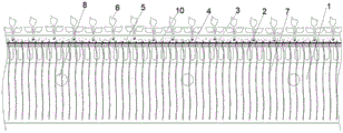
Fig. 2 is a longitudinal section of the road according to the utility model.
In the figure: the water collecting ditch 1, the support body 2, the water passing holes 3, the support plate 4, the planting soil 5, the green plants 6, the water absorbing cotton ropes 7, the water outlet 8, the water draining pipe 9 and the reverse filtering layer 10.
Detailed Description
Hereinafter, preferred embodiments of the present utility model will be described in detail with reference to the accompanying drawings. It should be understood that the preferred embodiments are presented by way of illustration only and not by way of limitation.
As shown in figures 1-2, a central separation belt for collecting road drainage comprises a water collecting ditch 1 which is arranged along a road and positioned at the central line position of the road, wherein a supporting body 2 is fixed on the top surface around the water collecting ditch 1, a plurality of water passing holes 3 are formed in the supporting body 2 at intervals along the length direction of the supporting body, the bottom ends of the water passing holes 3 are lower than the road surface, a supporting plate 4 with through holes is supported between the supporting bodies 2 above the water passing holes 3, planting soil 5 is covered on the supporting plate 4, green plants 6 are planted in the planting soil 5, a plurality of water absorbing cotton ropes 7 are buried in the planting soil 5 at intervals, the other ends of the water absorbing cotton ropes 7 penetrate through the through holes and extend into the inner bottom of the water collecting ditch 1, a plurality of water outlet 8 are arranged on the side wall of the water collecting ditch 1 at intervals along the longitudinal direction of the road, a water outlet 9 positioned under the road surface is connected to the water outlet 8, the other ends of the water outlet 9 are connected with a local drainage system, and the road surface on two sides of the water collecting ditch 1 is inclined towards the water collecting ditch in the transverse direction.
When raining, road surface rainwater gets into the storage of water catch bowl 1 through water hole 3, and overflow gets into drain pipe 9 and arranges to place drainage system when rainwater volume reaches outlet 8, and when arid rainless, green planting 6 obtains water by water catch bowl 1 through water-absorbing cotton rope 7, need not artifical watering, labour saving and time saving, with low costs, with road drainage system and central dividing belt integrated an organic whole, greatly reduced the construction degree of difficulty and cost.
The back filtering layer 10 is paved below the planting soil 5 on the supporting plate 4, the water absorbing cotton ropes 7 penetrate through the back filtering layer 10, and the planting soil 5 can be prevented from entering the water collecting ditch 1 from the through holes of the supporting plate 4 through the back filtering layer 10.
Preferably, the reverse filtration layer 10 is a reverse filtration geotextile or gravel.
A water inlet pipe is arranged in the water collecting ditch 1 and is connected with a municipal water pipe through an electric control valve, a water level monitor is arranged in the water collecting ditch and is electrically connected with a controller, and the controller is electrically connected with the electric control valve.
In arid season, when the water level monitor monitors that the water quantity in the water collecting ditch 1 is smaller than the set value, the controller controls the electric control valve to open and supplement water to the water collecting ditch 1 through the municipal water pipe and the water inlet pipe, so that the water collecting ditch 1 is guaranteed to have water, and the green plant 6 can obtain water supplement.
Preferably, the support body 2 is a reinforced concrete body.
The water passing holes 3 are vertically arranged strip-shaped holes, so that the water discharging capability of the road surface can be ensured.
Finally, it is noted that the above embodiments are only for illustrating the technical solution of the present utility model and not for limiting the same, and although the present utility model has been described in detail with reference to the preferred embodiments, it should be understood by those skilled in the art that modifications and equivalents may be made thereto without departing from the spirit and scope of the present utility model, which is intended to be covered by the claims of the present utility model.
Claims (6)
1. A central separator for collecting road drainage, characterized in that: including along road arrange and be located water catch bowl (1) of road central line position, water catch bowl (1) top surface is fixed with supporter (2) all around, be equipped with a plurality of water holes (3) along its length direction interval on supporter (2), water holes (3) bottom is less than the road surface, support between water holes (3) top supporter (2) has backup pad (4) of taking the through-hole, backup pad (4) are covered with planting soil (5), planting has green planting (6) in planting soil (5), planting soil (5) are buried a plurality of cotton ropes (7) that absorb water at intervals in, the cotton rope (7) other end that absorb water runs through the through-hole and stretches into water catch bowl (1) inner bottom, be equipped with a plurality of outlet (8) along road longitudinal spacing on water catch bowl (1) lateral wall, be connected with drain pipe (9) that are located under the road surface on outlet (8), the place drainage system is connected to the other end of drain pipe (9), the road surface of water catch bowl (1) both sides is in the slope towards the road water catch bowl in the lateral direction.
2. A central separator for collecting road drainage according to claim 1, wherein: the anti-filtration layer (10) is paved below the planting soil (5) on the supporting plate (4), and the water-absorbing cotton rope (7) penetrates through the anti-filtration layer (10).
3. A central separator for collecting road drainage according to claim 2, wherein: the reverse filtering layer (10) is reverse filtering geotextile or gravel.
4. A central separator for collecting road drainage according to claim 1, wherein: the water collecting ditch (1) is internally provided with a water inlet pipe, the water inlet pipe is connected with a municipal water pipe through an electric control valve, a water level monitor is arranged in the water collecting ditch and is electrically connected with a controller, and the controller is electrically connected with the electric control valve.
5. A central separator for collecting road drainage according to claim 1, wherein: the support body (2) is a reinforced concrete body.
6. A central separator for collecting road drainage according to any of claims 1 to 5, wherein: the water passing holes (3) are vertically arranged long strip-shaped holes.
Priority Applications (1)
| Application Number | Priority Date | Filing Date | Title |
|---|---|---|---|
| CN202320210425.XU CN219137524U (en) | 2023-02-14 | 2023-02-14 | Central separation belt for collecting road drainage |
Applications Claiming Priority (1)
| Application Number | Priority Date | Filing Date | Title |
|---|---|---|---|
| CN202320210425.XU CN219137524U (en) | 2023-02-14 | 2023-02-14 | Central separation belt for collecting road drainage |
Publications (1)
| Publication Number | Publication Date |
|---|---|
| CN219137524U true CN219137524U (en) | 2023-06-06 |
Family
ID=86560169
Family Applications (1)
| Application Number | Title | Priority Date | Filing Date |
|---|---|---|---|
| CN202320210425.XU Active CN219137524U (en) | 2023-02-14 | 2023-02-14 | Central separation belt for collecting road drainage |
Country Status (1)
| Country | Link |
|---|---|
| CN (1) | CN219137524U (en) |
-
2023
- 2023-02-14 CN CN202320210425.XU patent/CN219137524U/en active Active
Similar Documents
| Publication | Publication Date | Title |
|---|---|---|
| CN103758201B (en) | Band floods the clean integrated apparatus of surface flow rain-water accumulating and the method for culvert pipe | |
| CN101161053B (en) | A system for collecting and processing residence zone sanitary sewage and stormwater for roofs planting | |
| CN108193758B (en) | Sponge urban road storing and draining structure | |
| CN209039914U (en) | Road biological cleaning stranded belt based on sponge city | |
| CN111350233A (en) | Northern area field greenhouse area rainfall flood resource utilization device and construction method | |
| CN210580202U (en) | Green belt structure | |
| CN210002718U (en) | rainwater collection and cyclic utilization planting roof | |
| CN112982072B (en) | Green belt water storage and drainage curbstone system and water storage and drainage method | |
| CN205662974U (en) | Environmental rainwater branch matter collection in hillock district holds system | |
| CN219137524U (en) | Central separation belt for collecting road drainage | |
| CN112031114A (en) | Seepage stagnation type storage regulation sponge parking lot and rainwater storage regulation method | |
| CN218126031U (en) | Sponge city is with festival drainage and irrigation system | |
| CN109868877A (en) | Drainage system of freeway and construction method | |
| CN109797629A (en) | Drainage system of freeway and construction method | |
| CN111321703A (en) | Ecological water conservancy bank protection | |
| CN216552277U (en) | Porous hard type permeable pipe system embedded in concave green land | |
| CN211421345U (en) | Biological detention belt system | |
| CN108004877A (en) | A kind of sponge urban ecology square road foundation structure | |
| CN114592574A (en) | Intelligent landscape drainage method and drainage device | |
| CN210263232U (en) | A intelligent rain collector for gardens water conservation | |
| CN104213488B (en) | Compound rain-water drainage covered conduit canal and the construction method of green plants can be planted in top | |
| CN207959429U (en) | Sponge urban road receives drainage structure | |
| CN101606480B (en) | Rainwater permeation collection and irrigation saving system | |
| CN105908802B (en) | A kind of Mountain Area ecotype rainwater separating harvests system and construction method | |
| CN212294957U (en) | Seepage stagnation type storage regulation sponge parking lot |
Legal Events
| Date | Code | Title | Description |
|---|---|---|---|
| GR01 | Patent grant | ||
| GR01 | Patent grant |