CN219046485U - Intelligent cooling hot water self-cleaning photovoltaic device - Google Patents
Intelligent cooling hot water self-cleaning photovoltaic device Download PDFInfo
- Publication number
- CN219046485U CN219046485U CN202223002455.6U CN202223002455U CN219046485U CN 219046485 U CN219046485 U CN 219046485U CN 202223002455 U CN202223002455 U CN 202223002455U CN 219046485 U CN219046485 U CN 219046485U
- Authority
- CN
- China
- Prior art keywords
- water
- photovoltaic
- fixedly connected
- pipe
- circulating
- Prior art date
- Legal status (The legal status is an assumption and is not a legal conclusion. Google has not performed a legal analysis and makes no representation as to the accuracy of the status listed.)
- Active
Links
Images


Classifications
-
- Y—GENERAL TAGGING OF NEW TECHNOLOGICAL DEVELOPMENTS; GENERAL TAGGING OF CROSS-SECTIONAL TECHNOLOGIES SPANNING OVER SEVERAL SECTIONS OF THE IPC; TECHNICAL SUBJECTS COVERED BY FORMER USPC CROSS-REFERENCE ART COLLECTIONS [XRACs] AND DIGESTS
- Y02—TECHNOLOGIES OR APPLICATIONS FOR MITIGATION OR ADAPTATION AGAINST CLIMATE CHANGE
- Y02E—REDUCTION OF GREENHOUSE GAS [GHG] EMISSIONS, RELATED TO ENERGY GENERATION, TRANSMISSION OR DISTRIBUTION
- Y02E10/00—Energy generation through renewable energy sources
- Y02E10/50—Photovoltaic [PV] energy
Landscapes
- Photovoltaic Devices (AREA)
Abstract
The utility model discloses an intelligent cooling and hot water self-cleaning photovoltaic device which comprises a photovoltaic plate, wherein one end of the photovoltaic plate is fixedly connected with a guide plate, the lower surface of the guide plate is fixedly connected with a water guide pipe, and one end of the water guide pipe is fixedly connected with a rain water tank. This intelligence cooling hot water self-cleaning photovoltaic device, through photovoltaic board, clean water insulation can, circulating pump and circulating water pipe's setting, light Fu Banzhi connects to install on the support of raintank, utilize the raintank weight to prevent wind firmly, avoid destroying waterproof with photovoltaic board support nail on the roofing, clean water insulation can uses through circulating pump and circulating water pipe mutually support, make the heat in the photovoltaic cell and the heat production heat exchange of circulating water, the heat of photovoltaic cell is taken away to the flowing water and the heat preservation is stored in clean water insulation can, thereby reduce photovoltaic cell temperature, avoid the photovoltaic to reduce generating efficiency because of battery temperature is too high, lengthen photovoltaic module life-span, improve photovoltaic generating efficiency, reduce the water consumption.
Description
Technical Field
The utility model relates to the technical field of photovoltaics, in particular to an intelligent cooling and hot water self-cleaning photovoltaic device.
Background
The current development of the photovoltaic industry in China is rapid, the development of the energy source system is rapid, the energy source system is safe and efficient, the effect of new energy sources in the aspect of energy source conservation and supply is better exerted, and the assistance is realized by the carbon peak and carbon neutralization work.
The temperature of the photovoltaic module has a negative effect relation with the power generation efficiency, and the power generation capacity of the photovoltaic power station can be reduced by about 0.4% when the temperature rises for one degree. In summer, under the irradiation of the sun, the temperature of the photovoltaic module is up to more than 70 ℃, the photovoltaic power generation efficiency is seriously reduced, and the service life of the photovoltaic is shortened. Secondly, bird droppings, leaves, dust and the like deposited on the surface of the photovoltaic panel reduce the light transmittance of glass, reduce the power generation efficiency, seriously cause the photovoltaic to generate a hot spot effect and damage a photovoltaic element.
Disclosure of Invention
The utility model mainly aims to provide an intelligent cooling and hot water self-cleaning photovoltaic device which can effectively solve the problems in the background technology.
In order to achieve the above purpose, the technical scheme adopted by the utility model is as follows:
the utility model provides an intelligence cooling hot water is from clean photovoltaic device, includes the photovoltaic board, the one end fixedly connected with guide plate of photovoltaic board, the lower fixed surface of guide plate is connected with the water guide pipe, the one end fixedly connected with rainwater tank of water guide pipe, the last fixed surface of rainwater tank is connected with clean water insulation can, one side fixedly connected with circulating pump of clean water insulation can upper surface, the inside fixedly connected with circulating pipe of circulating pump.
In order to achieve the effect of being convenient for draining, the intelligent cooling and hot water self-cleaning photovoltaic device is characterized in that a draining hole is formed in the top of the outer surface of the clean water insulation box.
In order to achieve the effect of being convenient to connect, the intelligent cooling and hot water self-cleaning photovoltaic device is characterized in that a first circulating pipe is fixedly connected to one side of the outer surface of a photovoltaic panel, and a water inlet is formed in one end of the first circulating pipe.
In order to achieve the effect of facilitating heat dissipation of the photovoltaic cells, the intelligent cooling and hot water self-cleaning photovoltaic device is characterized in that the photovoltaic cells are fixedly connected to one side of the lower surface of the first circulating pipe, and the circulating branch pipes are fixedly connected to the outer surfaces of the photovoltaic cells.
In order to achieve the effect of being convenient for collecting and storing hot water, the intelligent cooling hot water self-cleaning photovoltaic device is characterized in that a second circulating pipe is fixedly connected to the lower surface of a photovoltaic panel, a water outlet is formed in one end of the second circulating pipe, a water outlet pipe is fixedly connected to the inside of the water outlet, and the water outlet pipe is fixedly connected with a clean water insulation box.
In order to achieve the effect of improving the photoelectric conversion rate, as the intelligent cooling hot water self-cleaning photovoltaic device, the upper surface of the photovoltaic panel is fixedly connected with glass, and the lower surface of the glass is fixedly connected with a first EVA adhesive film.
In order to achieve the effect of enhancing the bottom protection of the photovoltaic panel, the intelligent cooling and hot water self-cleaning photovoltaic device is characterized in that the back plate is fixedly connected to the lower surface of the photovoltaic panel, and the second EVA adhesive film is fixedly connected to the upper surface of the back plate.
In order to achieve the effect of being convenient for collecting rainwater, as the intelligent cooling and hot water self-cleaning photovoltaic device, the two sides of the outer surface of the guide plate are rotatably connected with the rotary wiper, the middle part of the upper surface of the photovoltaic plate is provided with the rotary water spray nozzle, and the guide plate is internally provided with the guide groove.
Compared with the prior art, the utility model has the following beneficial effects:
1. according to the photovoltaic panel solar photovoltaic module, the photovoltaic panel, the clean water insulation box, the circulating pump and the circulating water pipe are arranged, the light Fu Banzhi is connected and installed on the support of the rainwater tank, the rainwater tank is used for wind prevention and stabilization, the photovoltaic panel support is prevented from being nailed on a roof to damage water resistance, the installation procedure is simplified, the clean water insulation box is used in a matched mode through the circulating pump and the circulating water pipe, heat in the photovoltaic cell and the heat of the circulating water generate heat exchange, and the flowing water takes away the heat of the photovoltaic cell, so that the temperature of the photovoltaic cell is reduced, the power generation efficiency of the photovoltaic cell is prevented from being reduced due to overhigh temperature of the cell, the service life of a photovoltaic module is prolonged, the photovoltaic power generation efficiency is improved, the hot water generated in the photovoltaic cooling process flows into the clean water tank, heat preservation and storage are carried out, the domestic hot water is provided, and the hot water energy consumption of a resident is reduced.
2. According to the utility model, through the arrangement of the rotary wiper, the rotary water spray nozzle and the diversion trench, water mist is sprayed to the surface of the photovoltaic panel while the rotary water spray nozzle rotates, the surface of the photovoltaic panel is wetted, the two rotary wiper swings in turn, sundries such as bird droppings, leaves and dust accumulation on the surface of the photovoltaic panel are scraped, the surface is kept clean, the light transmittance of glass is improved, the photoelectric conversion rate is enhanced, the manual maintenance cost is reduced, a filter can be added in the diversion trench, thus rainwater on the photovoltaic surface is collected, and the device is used for cleaning the photovoltaic surface and flushing a toilet after filtering and precipitating, so that water resources are saved.
Drawings
Fig. 1 is a schematic side view structure of an intelligent cooling and hot water self-cleaning photovoltaic device according to embodiment 1 of the present utility model;
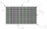
fig. 2 is a schematic diagram of a water circulation cooling system of an intelligent cooling hot water self-cleaning photovoltaic device according to embodiment 1 of the present utility model;
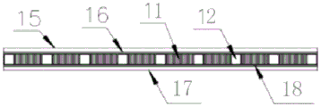
fig. 3 is a schematic cross-sectional view of a photovoltaic panel of an intelligent cooling and hot water self-cleaning photovoltaic device according to embodiment 1 of the present utility model;
fig. 4 is a schematic diagram of a rotating wiper of an intelligent cooling and hot water self-cleaning photovoltaic device according to embodiment 1 of the present utility model.
In the figure: 1. a photovoltaic panel; 2. a deflector; 3. a water discharge hole; 4. a water conduit; 5. a rain tank; 6. a clean water insulation box; 7. a circulation pump; 8. a circulating water pipe; 9. a water inlet; 10. a first circulation pipe; 11. a photovoltaic cell; 12. a circulation branch pipe; 13. a water outlet; 14. a second circulation pipe; 15. glass; 16. a first EVA adhesive film; 17. a back plate; 18. a second EVA adhesive film; 21. rotating the wiper; 22. a rotary water spray nozzle; 23. a diversion trench; 24. and a water outlet pipe.
Detailed Description
The following description of the embodiments of the present utility model will be made clearly and completely with reference to the accompanying drawings, in which it is apparent that the embodiments described are only some embodiments of the present utility model, but not all embodiments. All other embodiments, which can be made by those skilled in the art based on the embodiments of the utility model without making any inventive effort, are intended to be within the scope of the utility model.
Examples
As shown in fig. 1-4, an intelligent cooling and hot water self-cleaning photovoltaic device comprises a photovoltaic plate 1, wherein one end of the photovoltaic plate 1 is fixedly connected with a guide plate 2, the lower surface of the guide plate 2 is fixedly connected with a water guide pipe 4, one end of the water guide pipe 4 is fixedly connected with a rain water tank 5, the upper surface of the rain water tank 5 is fixedly connected with a clean water insulation box 6, one side of the upper surface of the clean water insulation box 6 is fixedly connected with a circulating pump 7, and the inner part of the circulating pump 7 is fixedly connected with a circulating water pipe 8.
When the solar photovoltaic panel is particularly used, through the arrangement of the guide plate 2, the guide pipe 4, the rain water tank 5, the clean water heat preservation box 6 and the circulating water pipe 8, the photovoltaic panel 1 is directly arranged on the bracket of the rain water tank 5, the weight of the rain water tank 5 is utilized for wind prevention and stabilization, the bracket of the photovoltaic panel 1 is prevented from being nailed on a roof to damage water resistance, the photovoltaic panel 1 is prevented from toppling over, the installation procedure is simplified, a filter can be added in the guide plate 2, the guide plate 2 collects rainwater and is stored in the rain water tank 5 through the guide pipe 4 after being filtered, the outlet of the rain water tank 5 is respectively connected with the rotary water spray nozzle 22 and the toilet water tank, water is provided for cleaning the photovoltaic panel 1 and flushing the toilet of a user, water resources are saved, the solar photovoltaic panel 11 and the clean water heat preservation box 6 can be provided with temperature sensors which respectively sense the temperature of the photovoltaic panel 11 and the clean water heat preservation box 6, when the temperature of the photovoltaic cell 11 is higher than the water temperature in the clean water heat preservation box 6 and the water temperature of the clean water heat preservation box 6 is lower than thirty-five ℃, the circulating pump 7 is automatically started, so that water in the clean water heat preservation box 6 flows into the plurality of circulating branch pipes 12 through the circulating water pipe 8, heat in the photovoltaic cell 11 and heat of circulating water generate heat exchange, flowing water takes away the heat of the photovoltaic cell 11, thereby reducing the temperature of the photovoltaic cell 11, and flows back into the clean water heat preservation box 6 through the second circulating pipe 14, when the water temperature in the clean water heat preservation box 6 is higher than thirty-five ℃, the circulating pump 7 is automatically closed, the valve of the tap water is automatically opened, tap water enters the water circulation heat dissipation system for cooling, intelligent water circulation cooling is realized, the temperature of the photovoltaic module is effectively reduced, the power generation efficiency is prevented from being reduced due to the overhigh temperature of the photovoltaic module, the service life of the photovoltaic module is prolonged, the power generation efficiency is improved, and the energy consumption of water is reduced, and saves water resources.
In the embodiment, the top of the outer surface of the clean water insulation box 6 is provided with a water discharge hole 3.
When the water-cleaning heat preservation box is particularly used, the water in the water-cleaning heat preservation box 6 is conveniently discharged through the arrangement of the water discharge holes 3.
In this embodiment, a first circulation pipe 10 is fixedly connected to one side of the outer surface of the photovoltaic panel 1, and a water inlet 9 is formed in one end of the first circulation pipe 10.
When the solar energy water heater is particularly used, through the arrangement of the first circulating pipe 10 and the water inlet 9, the front end of the water inlet of the water circulating system is connected with the circulating water pipe 8 and the tap water pipe respectively in two ways, the rear end of the water circulating system is connected with the first circulating pipe 10 and is positioned at the upper part of the photovoltaic panel 1, the second circulating pipe 14 is connected with the water outlet pipe and is positioned at the lower part of the photovoltaic panel 1, and the circulating water pipe 8, the first circulating pipe 10, the circulating branch pipe 12 and the second circulating pipe 14 are all made of red copper materials with high heat conductivity.
In this embodiment, a photovoltaic cell 11 is fixedly connected to one side of the lower surface of the first circulation pipe 10, and a circulation branch pipe 12 is fixedly connected to the outer surface of the photovoltaic cell 11.
When the photovoltaic device is particularly used, through the arrangement of the photovoltaic cells 11 and the circulating branch pipes 12, the plurality of circulating branch pipes 12 are connected with the first circulating pipe 10 and the second circulating pipe 14 and are positioned in gaps among the photovoltaic cells 11, and circulating water flowing in the pipes is utilized to take away heat of the photovoltaic cells 11, so that the effect of reducing the photovoltaic temperature is achieved.
In the embodiment, the lower surface of the photovoltaic panel 1 is fixedly connected with a second circulating pipe 14, one end of the second circulating pipe 14 is provided with a water outlet 13, the inside of the water outlet 13 is fixedly connected with a water outlet pipe 24, and the water outlet pipe 24 is fixedly connected with the clean water insulation box 6.
When the water-cleaning heat-insulation box is particularly used, through the arrangement of the second circulating pipe 14 and the water outlet 13, the water inlet of the water-cleaning heat-insulation box 6 is connected with the water outlet 13 of the second circulating pipe 14, hot water in a pipeline is collected and stored in a heat-insulation mode, the water outlet of the water-cleaning heat-insulation box 6 is connected with sanitary equipment such as a shower of a user, domestic hot water is provided for the user, water consumption is reduced, a heat-insulation layer is arranged on the outer side of the water-cleaning heat-insulation box 6, and the hot water can be stored in a heat-insulation mode.
In this embodiment, the upper surface of the photovoltaic panel 1 is fixedly connected with a glass 15, and the lower surface of the glass 15 is fixedly connected with a first EVA adhesive film 16.
When the photovoltaic cell is particularly used, through the arrangement of the glass 15, the glass 15 is fixed on the surface of the photovoltaic cell 11 through the first EVA adhesive film 16, so that the photovoltaic cell 11 is protected, meanwhile, the glass 15 is of a transparent structure, the photoelectric conversion rate can be improved, and the first EVA adhesive film 16 is a thermosetting adhesive film, has the advantages in the aspects of adhesive force, durability, optical characteristics and the like, and can resist high temperature, moisture, ultraviolet rays and the like.
In this embodiment, the lower surface of the photovoltaic panel 1 is fixedly connected with a back plate 17, and the upper surface of the back plate 17 is fixedly connected with a second EVA adhesive film 18.
When the photovoltaic panel is particularly used, through the arrangement of the backboard 17, the backboard 17 is fixed on the lower surface of the photovoltaic cell 11 through the second EVA adhesive film 18, so that the protection performance of the bottom of the photovoltaic panel 1 is enhanced.
In this embodiment, both sides of the outer surface of the deflector 2 are rotatably connected with a rotary wiper 21, a rotary water nozzle 22 is disposed in the middle of the upper surface of the photovoltaic panel 1, and a diversion trench 23 is formed in the deflector 2.
During specific use, through the setting of rotatory windscreen wiper 21 and rotatory water spout 22, control self-cleaning system regularly carries out the photovoltaic at predetermined time through the installation controller, rotatory water spout 22 is rotatory simultaneously to photovoltaic board 1 surface blowout water smoke, wet photovoltaic board 1 surface, two rotatory windscreen wipers 21 swing in turn, with the debris such as the bird's droppings on photovoltaic board 1 surface, leaf, laying dust are scraped, keep the surface clean, improve the luminousness of glass 15, the reinforcing photoelectric conversion rate, reduce the manual maintenance expense, the inside filter that can add of guiding gutter 23, thereby collect the rainwater on photovoltaic surface, after filtering, deposit, be used for clean photovoltaic surface and wash the stool pot, the water economy resource.
Working principle: the photovoltaic panel 1 is directly installed on a support of the rain water tank 5, a filter is added in the guide plate 2, collected rainwater is stored into the rain water tank 5 through the guide pipe 4 after being filtered, an outlet of the rain water tank 5 is respectively connected with the rotary water spray nozzles 22 and a toilet water tank, the rotary water spray nozzles 22 spray water mist to the surface of the photovoltaic panel 1 while rotating, the surface of the photovoltaic panel 1 is wetted, the two rotary wipers 21 swing in turn, sundries such as bird droppings, leaves and dust accumulation on the surface of the photovoltaic panel 1 are scraped, the surface is kept clean, the light transmittance of glass 15 is improved, temperature sensors can be installed at the photovoltaic cell 11 and the clean water thermal insulation box 6, the temperature of the photovoltaic cell 11 and the water temperature of the clean water thermal insulation box 6 are respectively sensed, when the temperature of the photovoltaic cell 11 is higher than the water temperature in the clean water thermal insulation box 6, and the water thermal insulation box 6 is lower than thirty-five degrees, the circulating pump 7 is automatically started, water in the thermal insulation box 6 flows into the plurality of circulating branch pipes 12 through the circulating water pipe 8, heat in the photovoltaic cell 11 exchanges heat with the heat of the circulating water, the photovoltaic cell 11 is taken away, the temperature of the photovoltaic cell 11 is lowered, and the photovoltaic cell 11 is automatically cooled through the second circulating water pipe 14, when the temperature of the circulating water thermal insulation box 6 is higher than the tap water thermal insulation box 6, the water is automatically cooled down, the water temperature is automatically is cooled, and when the water temperature in the thermal insulation box is higher than the water thermal insulation box is automatically cooled, and the water is automatically cooled down, and the water is cooled down by the circulating pump is automatically when the water pump is cooled, and the water is cooled.
The foregoing has shown and described the basic principles and main features of the present utility model and the advantages of the present utility model. It will be understood by those skilled in the art that the present utility model is not limited to the embodiments described above, and that the above embodiments and descriptions are merely illustrative of the principles of the present utility model, and various changes and modifications may be made without departing from the spirit and scope of the utility model, which is defined in the appended claims. The scope of the utility model is defined by the appended claims and equivalents thereof.
Claims (8)
1. The utility model provides an intelligence cooling hot water self-cleaning photovoltaic device, includes photovoltaic board (1), its characterized in that: one end fixedly connected with guide plate (2) of photovoltaic board (1), the lower fixed surface of guide plate (2) is connected with water guide pipe (4), the one end fixedly connected with rainwater tank (5) of water guide pipe (4), the last fixed surface of rainwater tank (5) is connected with clean water insulation can (6), one side fixedly connected with circulating pump (7) of clean water insulation can (6) upper surface, the inside fixedly connected with circulating pipe (8) of circulating pump (7).
2. The intelligent cooling, hot water self-cleaning photovoltaic device of claim 1, wherein: the top of the outer surface of the clean water insulation box (6) is provided with a water discharge hole (3).
3. The intelligent cooling, hot water self-cleaning photovoltaic device of claim 1, wherein: one side of the outer surface of the photovoltaic panel (1) is fixedly connected with a first circulating pipe (10), and one end of the first circulating pipe (10) is provided with a water inlet (9).
4. An intelligent cooling hot water self-cleaning photovoltaic device according to claim 3, characterized in that: one side of the lower surface of the first circulating pipe (10) is fixedly connected with a photovoltaic cell (11), and the outer surface of the photovoltaic cell (11) is fixedly connected with a circulating branch pipe (12).
5. The intelligent cooling, hot water self-cleaning photovoltaic device of claim 1, wherein: the photovoltaic panel (1) lower surface fixedly connected with second circulating pipe (14), delivery port (13) have been seted up to one end of second circulating pipe (14), the inside fixedly connected with outlet pipe (24) of delivery port (13), outlet pipe (24) are fixed connection with clean water insulation can (6).
6. The intelligent cooling, hot water self-cleaning photovoltaic device of claim 1, wherein: the upper surface of photovoltaic board (1) fixedly connected with glass (15), the lower surface of glass (15) is fixedly connected with first EVA glued membrane (16).
7. The intelligent cooling, hot water self-cleaning photovoltaic device of claim 1, wherein: the lower surface of the photovoltaic panel (1) is fixedly connected with a backboard (17), and the upper surface of the backboard (17) is fixedly connected with a second EVA adhesive film (18).
8. The intelligent cooling, hot water self-cleaning photovoltaic device of claim 1, wherein: both sides of the outer surface of the guide plate (2) are rotationally connected with rotary wipers (21), a rotary water spray nozzle (22) is arranged in the middle of the upper surface of the photovoltaic plate (1), and a guide groove (23) is formed in the guide plate (2).
Priority Applications (1)
| Application Number | Priority Date | Filing Date | Title |
|---|---|---|---|
| CN202223002455.6U CN219046485U (en) | 2022-11-09 | 2022-11-09 | Intelligent cooling hot water self-cleaning photovoltaic device |
Applications Claiming Priority (1)
| Application Number | Priority Date | Filing Date | Title |
|---|---|---|---|
| CN202223002455.6U CN219046485U (en) | 2022-11-09 | 2022-11-09 | Intelligent cooling hot water self-cleaning photovoltaic device |
Publications (1)
| Publication Number | Publication Date |
|---|---|
| CN219046485U true CN219046485U (en) | 2023-05-19 |
Family
ID=86318775
Family Applications (1)
| Application Number | Title | Priority Date | Filing Date |
|---|---|---|---|
| CN202223002455.6U Active CN219046485U (en) | 2022-11-09 | 2022-11-09 | Intelligent cooling hot water self-cleaning photovoltaic device |
Country Status (1)
| Country | Link |
|---|---|
| CN (1) | CN219046485U (en) |
-
2022
- 2022-11-09 CN CN202223002455.6U patent/CN219046485U/en active Active
Similar Documents
| Publication | Publication Date | Title |
|---|---|---|
| CN104160893B (en) | There is the energy-saving photovoltaic agricultural greenhouse of self-cleaning function | |
| TWM606840U (en) | Photovoltaic building material with ability of safe electric power generation | |
| CN202111101U (en) | Solar photovoltaic module with functions of automatic cleaning and cooling | |
| CN104170684B (en) | There is the multi-functional photovoltaic agricultural greenhouse of self-cleaning function | |
| CN108036434B (en) | Outer quick-witted intelligence cleaning device of air conditioner | |
| CN204157366U (en) | There is the energy-saving photovoltaic agricultural greenhouse of self-cleaning function | |
| CN208009776U (en) | Building energy conservation roofing | |
| CN206070726U (en) | Energy saving and environment friendly house | |
| CN114665814A (en) | Automatic cleaning system for photovoltaic panel and control method thereof | |
| CN210797855U (en) | Solar green building with water-saving device | |
| CN219046485U (en) | Intelligent cooling hot water self-cleaning photovoltaic device | |
| CN212115267U (en) | Clean heat sink of photovoltaic module | |
| CN218678974U (en) | Photovoltaic panel cleaning assembly of photovoltaic power station | |
| CN204157368U (en) | There is the multi-functional photovoltaic agricultural greenhouse of self-cleaning function | |
| CN108759110B (en) | Curved surface type solar heat collector | |
| CN213774634U (en) | Environment-friendly energy-saving green building | |
| CN214034307U (en) | Energy-saving environment-friendly building roof | |
| CN213682877U (en) | Energy-conserving roofing of green building | |
| CN211656082U (en) | Photovoltaic module belt cleaning device | |
| CN210507774U (en) | Novel energy-saving device for green building | |
| CN112695836A (en) | Solar energy intelligence outdoor device of washing hand based on membrane distillation | |
| CN113676131A (en) | Self-cleaning solar panel | |
| CN111478663A (en) | Clean heat sink of photovoltaic module | |
| CN218218603U (en) | Solar energy environment-friendly's field irrigation equipment control box | |
| CN208280466U (en) | A kind of greening building energy saving roofing |
Legal Events
| Date | Code | Title | Description |
|---|---|---|---|
| GR01 | Patent grant | ||
| GR01 | Patent grant |