CN218533196U - Laser cutting machine for machining steel templates - Google Patents
Laser cutting machine for machining steel templates Download PDFInfo
- Publication number
- CN218533196U CN218533196U CN202221144401.0U CN202221144401U CN218533196U CN 218533196 U CN218533196 U CN 218533196U CN 202221144401 U CN202221144401 U CN 202221144401U CN 218533196 U CN218533196 U CN 218533196U
- Authority
- CN
- China
- Prior art keywords
- portal frame
- steel form
- servo motor
- laser cutting
- cutting machine
- Prior art date
- Legal status (The legal status is an assumption and is not a legal conclusion. Google has not performed a legal analysis and makes no representation as to the accuracy of the status listed.)
- Active
Links
Images


Abstract
The utility model discloses a laser cutting machine for steel form processing, comprises a workbench, set up spacing spout on both ends respectively about the workstation, one of them set up first lead screw in the spacing spout, first lead screw one end is connected with first servo motor output, first servo motor set up in the workstation is served, threaded connection cover establishes portal frame one end on the first lead screw, the portal frame both ends all slide set up in the spacing spout, the rectangular hole is seted up on the portal frame top, set up the second lead screw in the rectangular hole, second lead screw one end is connected with second servo motor output, the utility model discloses a set up supplementary closing device work and will compress tightly the location to the steel form simultaneously in the laser cutting process, improve the stability of steel form, guarantee cutting process's quality, utilize supplementary closing device work to accomplish simultaneously and hoist and mount the transport with steel form automatic rising, improve its work efficiency.
Description
Technical Field
The utility model relates to a steel form cutting process technical field, concretely relates to laser cutting machine for steel form processing.
Background
The steel template is used for concrete pouring molding, and is widely applied to building engineering due to the characteristics of repeated use, attractive concrete pouring molding and the like.
Need process the cutting through laser cutting machine when steel form processing, laser cutting is irradiated by the cutting material through the laser beam of high power density, heat the material to vaporization temperature, the material can evaporate and form the hole, along with the removal of light beam to the material, the hole forms the joint-cutting in succession, thereby accomplish the cutting to the material, laser cutting belongs to one of the hot cutting method, and current steel form processing needs to press from both sides tight fixedly to the steel form in the course of working with laser cutting machine, and current fixed mode is fixed through locking bolt cooperation clamp plate, it is time-consuming and hard, and can't be applicable to the steel form of different specifications size, transport need lift up or transport to required position and hoist the transport again to the steel form after processing is accomplished simultaneously, artifical transport is lifted up the difficulty comparatively, can't satisfy the production demand.
SUMMERY OF THE UTILITY MODEL
The utility model aims at overcoming prior art's is not enough, and provide a laser cutting machine for steel form processing, comprises a workbench, set up spacing spout, one of them on the both ends respectively about the workstation set up first lead screw in the spacing spout, first lead screw one end is connected with first servo motor output, first servo motor set up in workstation one end is served, threaded connection cover establishes portal frame one end on the first lead screw, the portal frame both ends all slide set up in the spacing spout, the rectangular hole is seted up on the portal frame top, set up the second lead screw in the rectangular hole, second lead screw one end is connected with second servo motor output, second servo motor set up in on the portal frame one end, the threaded connection cover is established the transmission slider on the second lead screw, the transmission slider slide set up in the rectangular hole, the transmission slider bottom sets up laser generator, portal frame center department top sets up the mounting panel, set up supplementary closing device on the mounting panel, the portal frame below sets up supplementary hoisting device, supplementary hoisting device set up in the workstation.
Preferably, the auxiliary pressing device comprises a mounting frame, the mounting frame is arranged on the mounting plate, an air cylinder is arranged on the mounting frame, the output end of the air cylinder is provided with a transmission plate, two ends of the transmission plate are respectively provided with a lifting guide pillar, the lifting guide pillars all slide through the mounting plate, the bottom end of the lifting guide pillar is provided with a pressing plate, the bottom end of the pressing plate is provided with balls, and the pressing plate is arranged beside two sides of the output end of the laser generator.
Preferably, the ball is rotatably arranged in the mounting seat, the mounting seat is slidably arranged in a movable room, the movable room is arranged in the pressing plate, and the top end of the mounting seat is provided with a buffer spring connected with the pressing plate.
Preferably, the auxiliary lifting device comprises a lifting support, the lifting support is arranged in a through hole in a sliding mode, the through holes are formed in the left end and the right end of the workbench respectively, the bottom end of the lifting support is connected with the output end of an oil cylinder, and the oil cylinder is arranged at the bottom end of the workbench.
Preferably, the laser generator is arranged on an installation block, the installation block is arranged at the output end of the electric push rod, and the electric push rod is arranged on the transmission sliding block.
The utility model has the advantages that: structural design is reasonable, will compress tightly the location to the steel form simultaneously through setting up supplementary closing device work in laser cutting process, improves the stability of steel form, guarantees the quality of cutting process, is applicable to the product of different specifications size, and labour saving and time saving utilizes supplementary closing device work to be convenient for simultaneously to process and accomplishes and break away from the workstation with the automatic rising of steel form and hoist the transport, need not artifical transport, improves its work efficiency.
Drawings
The invention will now be described, by way of example, with reference to the accompanying drawings, in which:
fig. 1 is a schematic perspective view of the present invention;
fig. 2 is a schematic perspective view of the present invention;
fig. 3 is a schematic perspective view of the present invention;
fig. 4 is a schematic perspective view of the lifting bracket of the present invention;
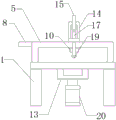
fig. 5 is a schematic side view of the present invention.
In the figure: 1. a work table; 2. a limiting chute; 3. a first lead screw; 4. a first servo motor; 5. a gantry; 6. a rectangular hole; 7. a second screw rod; 8. a second servo motor; 9. a transmission slide block; 10. a laser generator; 11. mounting a plate; 12. a through hole; 13. a lifting support; 14. A mounting frame; 15. a cylinder; 16. a drive plate; 17. a lifting guide post; 18. pressing a plate; 19. a ball bearing; 20. and an oil cylinder.
Detailed Description
Any feature disclosed in this specification may be replaced by alternative features serving an equivalent or similar purpose, unless expressly stated otherwise. That is, unless expressly stated otherwise, each feature is only an example of a generic series of equivalent or similar features.
The technical solutions in the embodiments of the present invention will be described clearly and completely with reference to the accompanying drawings in the embodiments of the present invention, and it is obvious that the described embodiments are only some embodiments of the present invention, not all embodiments. Based on the embodiments in the present invention, all other embodiments obtained by a person skilled in the art without creative work belong to the protection scope of the present invention.
In the description of the present invention, it should be noted that the terms "upper", "lower", "inner", "outer", "front end", "rear end", "both ends", "one end", "the other end", and the like indicate orientations or positional relationships based on the orientations or positional relationships shown in the drawings, and are only for convenience of description and simplification of description, but do not indicate or imply that the device or element to be referred must have a specific orientation, be constructed in a specific orientation, and be operated, and thus, should not be construed as limiting the present invention. Furthermore, the terms "first" and "second" are used for descriptive purposes only and are not to be construed as indicating or implying relative importance.
In the description of the present invention, it is to be noted that, unless otherwise explicitly specified or limited, the terms "mounted", "provided", "connected", and the like are to be understood in a broad sense, such as "connected", which may be fixedly connected, welded, riveted, bonded, and the like, or detachably connected, screwed, keyed, pinned, and the like, or integrally connected; can be mechanically or electrically connected; they may be connected directly or indirectly through intervening media, or they may be interconnected between two elements. The specific meaning of the above terms in the present invention can be understood as a specific case by those skilled in the art.
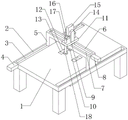
The laser cutting machine for machining the steel template comprises a workbench 1, wherein limiting sliding grooves 2 are formed in the left end and the right end of the workbench 1 respectively, one of the limiting sliding grooves is internally provided with a first lead screw 3, one end of the first lead screw 3 is connected with the output end of a first servo motor 4, the first servo motor 4 is arranged at one end of the workbench 1, one end of a portal frame 5 is arranged on the first lead screw 3 in a threaded connection sleeve mode, the two ends of the portal frame 5 are arranged in the limiting sliding grooves 2 in a sliding mode, a rectangular hole 6 is formed in the top end of the portal frame 5, a second lead screw 7 is arranged in the rectangular hole 6, one end of the second lead screw 7 is connected with the output end of a second servo motor 8, the second servo motor 8 is arranged at one end of the portal frame 5, a transmission slide block 9 is arranged on the second lead screw 7 in a sliding mode, the bottom end of the transmission slide block 9 is provided with a laser 10, the top end of the central position of the portal frame 5 is provided with a mounting plate 11, an auxiliary pressing device is arranged on the mounting plate 11, a lifting device is arranged below the portal frame 5, and an auxiliary lifting device is arranged in the workbench 1. It should be noted that the first servo motor 4 works to drive the first lead screw 3 to rotate, the portal frame 5 moves in the limiting chute 2 along with the first lead screw, so as to achieve the effect of adjusting the working position of the laser generator 10, the second servo motor 8 works to drive the second lead screw 7 to rotate, and the transmission slide block 9 drives the laser generator 10 to move on the portal frame 5 to the required working position; supplementary closing device work is convenient for compress tightly stably to the steel form at laser generator 10 during operation, and supplementary hoisting device work will be convenient for raise the steel form that the processing was accomplished and hoist the transport.
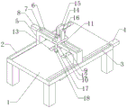
Specifically, supplementary closing device includes mounting bracket 14, mounting bracket 14 set up in on the mounting panel 11, set up cylinder 15 on the mounting bracket 14, the 15 output of cylinder sets up driving plate 16, set up lift guide pillar 17 on the driving plate 16 both ends respectively, lift guide pillar 17 all slides and runs through mounting panel 11, lift guide pillar 17 bottom sets up clamp plate 18, the 18 bottom of clamp plate sets up ball 19, clamp plate 18 set up in by the output both sides of laser generator 10. It should be noted that the cylinder 15 drives the transmission plate 16 to move when working, the lifting guide pillar 17 moves with the transmission plate to drive the pressing plate 18 to approach to and be away from the steel form, and the balls 19 are arranged to facilitate the auxiliary pressing device to press the steel form and move in cooperation with the movement of the portal frame 5, so that the steel form is pressed locally.
Specifically, the ball 19 rotates and sets up in the mount pad, the mount pad slides and sets up in the activity room, the activity room is opened and is located in the clamp plate 18, the mount pad top sets up buffer spring and be connected with clamp plate 18. It should be noted that, the arrangement of the ball 19 in cooperation with the mounting seat and the buffer spring enables the ball to be driven by the pressing plate 18 to be pressed downwards, so as to achieve a buffering protection effect and avoid damage to the product due to excessive movement and extrusion.
Particularly, supplementary hoisting device includes lifting support 13, lifting support 13 slides and sets up in through-hole 12, through-hole 12 is seted up respectively on workstation 1 left and right sides both ends, lifting support 13 bottom is connected with hydro-cylinder 20 output, hydro-cylinder 20 set up in workstation 1 bottom. It should be noted that, the oil cylinder 20 drives the lifting support 13 to lift in the through hole 12 to lift the steel form for hoisting, and when lifting is not needed, the top end of the lifting support 13 is flush with the upper surface of the workbench 1.
Particularly, laser generator 10 sets up on the installation piece, the installation piece sets up on electric putter output, electric putter set up in on the transmission slider 9. It should be noted that, the laser generator 10 is matched with the mounting block through the electric push rod, so that the working height of the laser generator 10 can be adjusted conveniently, and the laser generator is suitable for processing products with different thicknesses.
The working principle of the specific implementation mode is as follows: firstly, a product is placed on a workbench 1, then the first screw rod 3 is driven to rotate through the work of a first servo motor 4 according to requirements, a portal frame 5 moves in a limiting sliding groove 2 along with the movement of the portal frame, the working position of a laser generator 10 is adjusted, meanwhile, a second servo motor 8 drives a second screw rod 7 to rotate through the work of the second servo motor, a transmission slide block 9 drives the laser generator 10 to move on the portal frame 5 to a required working position, meanwhile, the working height of the laser generator 10 can be adjusted through the work of an electric push rod, the product is better cut and processed, a transmission plate 16 is driven to move through the work of an air cylinder 15 in the cutting process, a lifting guide pillar 17 moves along with the lifting movement to drive a pressing plate 18 to be close to and far away from a steel template, the steel template is moved through the movement of the portal frame 5 in a manner of being convenient to press the steel template through arranging a ball 19, the steel template is better pressed locally, after the cutting is completed, the portal frame 5 moves to a limiting position to be far away from the product, the lifting support 13 is driven to move in a through the work of the oil cylinder 20 to lift the steel template for lifting, and lifting support 13 to be lifted, and then lifted, and the lifting support can be lifted after the lifting support is reset.
The present invention is not limited to the foregoing embodiments. The invention extends to any novel feature or any novel combination of features disclosed in this specification, and to any novel method or process steps or any novel combination of features disclosed.
Claims (5)
1. The utility model provides a laser cutting machine for steel form processing, includes workstation (1), its characterized in that: the left end and the right end of the workbench (1) are respectively provided with a limiting sliding chute (2), wherein a first screw rod (3) is arranged in one of the limiting sliding chutes (2), one end of the first screw rod (3) is connected with the output end of the first servo motor (4), the first servo motor (4) is arranged on one end of the workbench (1), one end of a portal frame (5) is sleeved on the first screw rod (3) in a threaded connection way, both ends of the portal frame (5) are arranged in the limiting sliding chute (2) in a sliding way, a rectangular hole (6) is formed in the top end of the portal frame (5), a second screw rod (7) is arranged in the rectangular hole (6), one end of the second screw rod (7) is connected with the output end of a second servo motor (8), the second servo motor (8) is arranged on one end of the portal frame (5), the second screw rod (7) is sleeved with a transmission slide block (9) in a threaded connection way, the transmission slide block (9) is arranged in the rectangular hole (6) in a sliding way, the bottom end of the transmission slide block (9) is provided with a laser generator (10), the top end of the center of the portal frame (5) is provided with a mounting plate (11), an auxiliary pressing device is arranged on the mounting plate (11), an auxiliary lifting device is arranged below the portal frame (5), and the auxiliary lifting device is arranged in the workbench (1).
2. The laser cutting machine for steel form machining according to claim 1, characterized in that: the auxiliary pressing device comprises a mounting frame (14), the mounting frame (14) is arranged on the mounting plate (11), an air cylinder (15) is arranged on the mounting frame (14), a transmission plate (16) is arranged at the output end of the air cylinder (15), lifting guide pillars (17) are arranged at two ends of the transmission plate (16) respectively, the lifting guide pillars (17) all slide and penetrate through the mounting plate (11), a pressing plate (18) is arranged at the bottom end of the lifting guide pillars (17), balls (19) are arranged at the bottom end of the pressing plate (18), and the pressing plate (18) is arranged beside two sides of the output end of the laser generator (10).
3. The laser cutting machine for steel form machining according to claim 2, characterized in that: the ball (19) rotates and is arranged in the mounting seat, the mounting seat is arranged in the movable room in a sliding mode, the movable room is arranged in the pressing plate (18), and the top end of the mounting seat is provided with a buffer spring which is connected with the pressing plate (18).
4. The laser cutting machine for steel form machining according to claim 1, characterized in that: auxiliary lifting device includes lifting support (13), lifting support (13) slide to set up in through-hole (12), through-hole (12) are seted up respectively on both ends about workstation (1), lifting support (13) bottom is connected with hydro-cylinder (20) output, hydro-cylinder (20) set up in workstation (1) bottom.
5. The laser cutting machine for steel form machining of claim 1, wherein: laser generator (10) set up on the installation piece, the installation piece sets up on electric putter output, electric putter set up in on transmission slider (9).
Priority Applications (1)
| Application Number | Priority Date | Filing Date | Title |
|---|---|---|---|
| CN202221144401.0U CN218533196U (en) | 2022-05-12 | 2022-05-12 | Laser cutting machine for machining steel templates |
Applications Claiming Priority (1)
| Application Number | Priority Date | Filing Date | Title |
|---|---|---|---|
| CN202221144401.0U CN218533196U (en) | 2022-05-12 | 2022-05-12 | Laser cutting machine for machining steel templates |
Publications (1)
| Publication Number | Publication Date |
|---|---|
| CN218533196U true CN218533196U (en) | 2023-02-28 |
Family
ID=85258449
Family Applications (1)
| Application Number | Title | Priority Date | Filing Date |
|---|---|---|---|
| CN202221144401.0U Active CN218533196U (en) | 2022-05-12 | 2022-05-12 | Laser cutting machine for machining steel templates |
Country Status (1)
| Country | Link |
|---|---|
| CN (1) | CN218533196U (en) |
Cited By (1)
| Publication number | Priority date | Publication date | Assignee | Title |
|---|---|---|---|---|
| CN116511733A (en) * | 2023-06-01 | 2023-08-01 | 湖南兴涟钢铁有限公司 | Cold-rolled strip steel cutting device |
-
2022
- 2022-05-12 CN CN202221144401.0U patent/CN218533196U/en active Active
Cited By (2)
| Publication number | Priority date | Publication date | Assignee | Title |
|---|---|---|---|---|
| CN116511733A (en) * | 2023-06-01 | 2023-08-01 | 湖南兴涟钢铁有限公司 | Cold-rolled strip steel cutting device |
| CN116511733B (en) * | 2023-06-01 | 2023-10-27 | 湖南兴涟钢铁有限公司 | Cold-rolled strip steel cutting device |
Similar Documents
| Publication | Publication Date | Title |
|---|---|---|
| US11097327B2 (en) | Bending machine | |
| CN206296388U (en) | Feed device before plate shearing machine | |
| CN207359685U (en) | A kind of automobile handware stamping equipment of automatic positioning | |
| CN208214795U (en) | A kind of digital controlled rotary plate shearing machine and the production system with the plate shearing machine | |
| CN207494256U (en) | A kind of bender | |
| CN218533196U (en) | Laser cutting machine for machining steel templates | |
| CN112010031A (en) | Concrete block clamping and stacking tool | |
| CN110757017A (en) | Fixing device for laser cutting | |
| CN219745918U (en) | Ship fitting bending die tooling | |
| CN217529976U (en) | Hardware processing is with semi-automatic chamfer all-in-one that drills | |
| CN213317831U (en) | Drilling machine tool for die machining | |
| CN210305168U (en) | Hydraulic plate bending machine | |
| CN210588105U (en) | Composite processing machine tool for shearing, bending and punching sheet metal parts | |
| CN214768431U (en) | Adjustable punch press for aluminum alloy machining | |
| CN212525740U (en) | Discharging device for cutter production | |
| CN211135269U (en) | Punching machine is used in metalwork processing of convenient usefulness | |
| CN216939362U (en) | Corner cutting and notching integrated machine | |
| CN220372025U (en) | Oblique punching composite die | |
| CN210703652U (en) | Machine tool body pressing plate device | |
| CN216264260U (en) | Automatic welding equipment for building aluminum alloy machining | |
| CN216914580U (en) | High polymer material die cutting technology of paper breaking knife | |
| CN220311981U (en) | Metal material cutting device | |
| CN219747047U (en) | Multifunctional plate and tube cutting platform | |
| CN218800053U (en) | Robot structure capable of realizing multi-directional welding | |
| CN211467451U (en) | Bending machine |
Legal Events
| Date | Code | Title | Description |
|---|---|---|---|
| GR01 | Patent grant | ||
| GR01 | Patent grant |