CN218200981U - Glass coating production is with automatic mechanism of snatching - Google Patents

Glass coating production is with automatic mechanism of snatching Download PDF

Info

Publication number
CN218200981U
CN218200981U CN202222195481.9U CN202222195481U CN218200981U CN 218200981 U CN218200981 U CN 218200981U CN 202222195481 U CN202222195481 U CN 202222195481U CN 218200981 U CN218200981 U CN 218200981U
Authority
CN
China
Prior art keywords
lead screw
grabbing mechanism
coating production
glass coating
automatic
Prior art date
Legal status (The legal status is an assumption and is not a legal conclusion. Google has not performed a legal analysis and makes no representation as to the accuracy of the status listed.)
Active
Application number
CN202222195481.9U
Other languages
Chinese (zh)
Inventor
武春建
Current Assignee (The listed assignees may be inaccurate. Google has not performed a legal analysis and makes no representation or warranty as to the accuracy of the list.)
Tunghsu Technology Group Co Ltd
Original Assignee
Dongguang County Aixin Glass Products Co ltd
Priority date (The priority date is an assumption and is not a legal conclusion. Google has not performed a legal analysis and makes no representation as to the accuracy of the date listed.)
Filing date
Publication date
Application filed by Dongguang County Aixin Glass Products Co ltd filed Critical Dongguang County Aixin Glass Products Co ltd
Priority to CN202222195481.9U priority Critical patent/CN218200981U/en
Application granted granted Critical
Publication of CN218200981U publication Critical patent/CN218200981U/en
Active legal-status Critical Current
Anticipated expiration legal-status Critical

Links

Images

Landscapes

  • Re-Forming, After-Treatment, Cutting And Transporting Of Glass Products (AREA)

Abstract

The utility model discloses a glass coating production is with automatic mechanism of snatching, include the sliding seat along the workstation mesa back-and-forth movement, be provided with the arm that snatchs that extends to one side on the sliding seat, it is keeping away from to snatch the arm the one end of sliding seat is provided with the returning face plate, be provided with the telescopic mounting panel on the returning face plate, the upper and lower both ends of mounting panel are provided with the mounting bracket that can synchronous adjustment, be provided with vacuum chuck on the mounting bracket. The utility model discloses a set up a rotatable returning face plate on snatching the arm to set up vacuum chuck on the returning face plate, adsorb the glass board when snatching when vacuum chuck, can realize the apron of glass board position through the rotation of returning face plate, thereby can stick up horizontal glass board, or violently come with the glass board of putting vertically, this makes whole snatching the mechanism more nimble, has also saved staff's work load, brings very big facility for handling work.

Description

Glass coating production is with automatic mechanism of snatching
Technical Field
The utility model relates to a glass anchor clamps technical field especially relates to a glass coating production is with automatic mechanism that snatchs.
Background
Glass is a material which is often seen in daily life and covers the square of our life, generally, coating is carried out on the surface of the glass in order to improve the product performance of the glass, the coated glass has better strength, the glass needs to be carried in the coating processing process, all the previous glass grabbing equipment uses a vacuum chuck to suck the glass, then the glass is horizontally conveyed and put down, the grabbing equipment is very inflexible in movement, the flat glass needs to be placed vertically by a worker, great inconvenience is brought to the worker, the glass cannot be grabbed by the previous grabbing equipment, the glass still needs to be flatly placed by the worker, and the whole process is very complicated.
SUMMERY OF THE UTILITY MODEL
The utility model aims to avoid the disadvantages of the prior art and provide an automatic grabbing mechanism for glass coating production, thereby effectively solving the disadvantages existing in the prior art.
In order to achieve the above purpose, the utility model adopts the technical proposal that: an automatic grabbing mechanism for glass coating production comprises a movable seat moving back and forth along the table surface of a workbench, wherein a grabbing arm extending to one side is arranged on the movable seat, a turnover plate is arranged at one end of the grabbing arm far away from the movable seat, a telescopic mounting plate is arranged on the turnover plate, mounting frames capable of being synchronously adjusted are arranged at the upper end and the lower end of the mounting plate, and a vacuum chuck is arranged on the mounting frames;
be provided with positive and negative lead screw along vertical direction on the mounting panel, positive and negative lead screw passes through motor drive and rotates, the mounting bracket is installed respectively positive and negative lead screw opposite direction's both ends, the mounting panel is corresponding the position of positive and negative lead screw both sides still is provided with the guide bar, the guide bar passes the mounting bracket.
Further, be provided with the drive lead screw on the workstation, the drive lead screw rotates under servo motor's control, the sliding seat with drive lead screw is connected.
Furthermore, the workbench is provided with slide rails at positions corresponding to two sides of the driving screw rod, the lower end of the movable seat is provided with a slide block, and the slide block is installed on the slide rails.
Furthermore, servo motor installs the lower extreme of workstation, servo motor's drive end with the drive lead screw passes through belt transmission.
Furthermore, the grabbing arm is provided with a turnover oil cylinder above one end close to the turnover plate, the turnover plate is hinged to the end of the grabbing arm, the end of the turnover oil cylinder is hinged to the grabbing arm, and a piston rod of the turnover oil cylinder is hinged to the turnover plate.
Furthermore, a plurality of telescopic oil cylinders are transversely arranged on one side of the turnover plate far away from the hinged end of the turnover plate, and the mounting plate is fixedly arranged on piston rods of the telescopic oil cylinders.
Further, be provided with the sliding block on the mounting bracket, positive and negative lead screw with the guide bar all passes the sliding block.
Furthermore, the bottom of workstation is provided with the supporting leg.
The above technical scheme of the utility model following beneficial effect has: the utility model discloses a set up a rotatable returning face plate on snatching the arm to set up vacuum chuck on the returning face plate, adsorb the glass board when snatching when vacuum chuck, can realize the apron of glass board position through the rotation of returning face plate, thereby can stick up horizontal glass board, or violently come with the glass board of putting vertically, this makes whole snatching the mechanism more nimble, has also saved staff's work load, brings very big facility for handling work.
Drawings
Fig. 1 is a schematic view of a front view cross-sectional structure of an embodiment of the present invention;
fig. 2 is an enlarged view of a point a in fig. 1.
Detailed Description
In order to make the above objects, features and advantages of the present invention more clearly understood, the following detailed description of the present invention is made in conjunction with the accompanying drawings and the detailed description, it is to be noted that the features of the embodiments and examples of the present invention may be combined with each other without conflict.
In the following description, numerous specific details are set forth in order to provide a thorough understanding of the present invention, however, the present invention may be practiced in other ways than those specifically described herein, and therefore the scope of the present invention is not limited by the specific embodiments disclosed below.
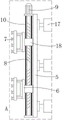
As shown in fig. 1-2, the automatic grabbing mechanism for glass coating production in this embodiment includes a movable seat 2 moving back and forth along a table top of a workbench 1, a grabbing arm 3 extending to one side is disposed on the movable seat 2, a turning plate 4 is disposed at one end of the grabbing arm 3 away from the movable seat 2, a telescopic mounting plate 5 is disposed on the turning plate 4, mounting frames 6 capable of being adjusted synchronously are disposed at upper and lower ends of the mounting plate 5, and a vacuum chuck 7 is disposed on the mounting frame 6;
installing plate 5 is last to be provided with positive and negative lead screw 8 along vertical direction, and positive and negative lead screw 8 passes through the drive of motor 9 and rotates, and installing frame 6 is installed respectively at the both ends that 8 screw thread opposite directions of positive and negative lead screw, and installing plate 5 still is provided with guide bar 10 in the position that corresponds 8 both sides of positive and negative lead screw, and guide bar 10 passes installing frame 6.
The motor 9 drives the positive and negative screw rods 8 to rotate, and the mounting frames 6 are mounted at two ends of the positive and negative screw rods 8, which are opposite in thread direction, so that the two mounting frames 6 can move towards the center of the positive and negative screw rods 8 simultaneously or move away from each other simultaneously, and therefore the space between the vacuum suction cups 7 on the mounting frames 6 is changed, and the glass plates of different specifications can be stably grabbed.
A driving lead screw 11 is arranged on the workbench 1, the driving lead screw 11 rotates under the control of a servo motor 12, and the movable seat 2 is connected with the driving lead screw 11.
The workbench 1 is provided with slide rails 13 at positions corresponding to two sides of the driving screw rod 11, the lower end of the movable seat 2 is provided with a slide block 14, and the slide block 14 is installed on the slide rails 13.
The driving screw 11 is driven to rotate by the servo motor 12, and the driving screw 11 drives the movable base 2 to move back and forth along the slide rail 13.
A servo motor 12 is arranged at the lower end of the workbench 1, and the driving end of the servo motor 12 is in transmission with the driving screw rod 11 through a belt 15.
The grabbing arm 3 is provided with a turnover oil cylinder 16 above one end close to the turnover plate 4, the turnover plate 4 is hinged with the end part of the grabbing arm 3, the end part of the turnover oil cylinder 16 is hinged with the grabbing arm 3, and a piston rod of the turnover oil cylinder 16 is hinged with the turnover plate 4.
When the piston rod of the turnover oil cylinder 16 extends out, the turnover plate 4 is driven by the piston rod to rotate, and the vertically arranged turnover plate 4 rotates downwards, so that the vacuum sucker 7 is vertically arranged downwards to grab the glass plate.
The turnover plate 4 is transversely provided with a plurality of telescopic oil cylinders 17 at one side far away from the hinged end, and the mounting plate 5 is fixedly arranged on the piston rods of the telescopic oil cylinders 17.
The telescopic oil cylinder 17 can drive the mounting plate 5 to move left and right by the telescopic piston rod, so that the vacuum chuck 7 moves and grabs the glass plate.
The mounting frame 6 is provided with a sliding block 18, and the forward and reverse screw rods 8 and the guide rod 10 both penetrate through the sliding block 18.
The bottom of the working platform 1 is provided with support legs 19.
The utility model discloses a theory of operation does: firstly, a servo motor 12 controls a driving screw rod 11 to rotate, so that a grabbing arm 3 is controlled to move, when the grabbing arm 3 moves to the position of a glass plate, the servo motor 12 stops working, then a telescopic oil cylinder 17 is started, the telescopic oil cylinder 17 stretches, a piston rod of the telescopic oil cylinder drives a vacuum sucker 7 to move to the position of the vertically placed glass plate and grab the glass plate, after the glass plate is grabbed by the vacuum sucker 7, the telescopic oil cylinder 17 contracts, meanwhile, an overturning oil cylinder 16 starts and controls a turnover plate 4 to rotate downwards, so that the vertically placed glass plate is placed transversely, then the glass plate is moved to a processing station through the movement of the grabbing arm 3, then the telescopic oil cylinder 17 is started again and puts down the glass plate, then the vacuum sucker 7 stops sucking work, the glass plate is placed on the processing station, the process is repeated, the processing and feeding work of the glass plate can be realized, when the glass plate needs to be moved and unloaded, the turnover plate 4 can be controlled to rotate downwards, then the vertically downward vacuum sucker 7 can suck the glass plate, then the glass plate can be placed on the station, the glass plate can be placed horizontally, the glass plate can be transported to a specified area, and the glass plate can be conveniently transported, and the glass plate can be transported to be lifted and placed in a transportation area.
The embodiments of the present invention have been presented for purposes of illustration and description, and are not intended to be exhaustive or limited to the invention in the form disclosed. Many modifications and variations will be apparent to practitioners skilled in this art. The embodiment was chosen and described in order to best explain the principles of the invention and the practical application, and to enable others of ordinary skill in the art to understand the invention for various embodiments with various modifications as are suited to the particular use contemplated.

Claims (8)

1. The utility model provides a glass coating production is with automatic mechanism of snatching which characterized in that: the automatic clamping device comprises a movable seat which moves back and forth along the table top of a workbench, wherein a grabbing arm extending to one side is arranged on the movable seat, a turnover plate is arranged at one end of the grabbing arm far away from the movable seat, a telescopic mounting plate is arranged on the turnover plate, mounting frames capable of being synchronously adjusted are arranged at the upper end and the lower end of the mounting plate, and a vacuum chuck is arranged on the mounting frames;
be provided with positive and negative lead screw along vertical direction on the mounting panel, positive and negative lead screw passes through motor drive and rotates, the mounting bracket is installed respectively positive and negative lead screw opposite direction's both ends, the mounting panel is corresponding the position of positive and negative lead screw both sides still is provided with the guide bar, the guide bar passes the mounting bracket.
2. The automatic grabbing mechanism for glass coating production of claim 1, which is characterized in that: the workbench is provided with a driving lead screw, the driving lead screw rotates under the control of the servo motor, and the movable seat is connected with the driving lead screw.
3. The automatic grabbing mechanism for glass coating production of claim 2, wherein the automatic grabbing mechanism comprises: the workbench is provided with slide rails at positions corresponding to two sides of the driving screw rod, the lower end of the movable seat is provided with a slide block, and the slide block is arranged on the slide rails.
4. The automatic grabbing mechanism for glass coating production of claim 3, wherein the automatic grabbing mechanism comprises: the servo motor is installed at the lower end of the workbench, and the driving end of the servo motor is in transmission with the driving lead screw through a belt.
5. The automatic grabbing mechanism for glass coating production of claim 1, wherein the automatic grabbing mechanism comprises: the grabbing arm is provided with a turnover oil cylinder above one end close to the turnover plate, the turnover plate is hinged to the end of the grabbing arm, the end of the turnover oil cylinder is hinged to the grabbing arm, and a piston rod of the turnover oil cylinder is hinged to the turnover plate.
6. The automatic grabbing mechanism for glass coating production of claim 1, wherein the automatic grabbing mechanism comprises: a plurality of telescopic oil cylinders are transversely arranged on one side of the turnover plate far away from the hinged end of the turnover plate, and the mounting plate is fixedly arranged on a piston rod of each telescopic oil cylinder.
7. The automatic grabbing mechanism for glass coating production of claim 1, wherein the automatic grabbing mechanism comprises: be provided with the sliding block on the mounting bracket, positive and negative lead screw with the guide bar all passes the sliding block.
8. The automatic grabbing mechanism for glass coating production of claim 1, which is characterized in that: the bottom of the workbench is provided with supporting legs.
CN202222195481.9U 2022-08-22 2022-08-22 Glass coating production is with automatic mechanism of snatching Active CN218200981U (en)

Priority Applications (1)

Application Number Priority Date Filing Date Title
CN202222195481.9U CN218200981U (en) 2022-08-22 2022-08-22 Glass coating production is with automatic mechanism of snatching

Applications Claiming Priority (1)

Application Number Priority Date Filing Date Title
CN202222195481.9U CN218200981U (en) 2022-08-22 2022-08-22 Glass coating production is with automatic mechanism of snatching

Publications (1)

Publication Number Publication Date
CN218200981U true CN218200981U (en) 2023-01-03

Family

ID=84658797

Family Applications (1)

Application Number Title Priority Date Filing Date
CN202222195481.9U Active CN218200981U (en) 2022-08-22 2022-08-22 Glass coating production is with automatic mechanism of snatching

Country Status (1)

Country Link
CN (1) CN218200981U (en)

Cited By (1)

* Cited by examiner, † Cited by third party
Publication number Priority date Publication date Assignee Title
CN117227607A (en) * 2023-11-07 2023-12-15 国机传感科技有限公司 Intelligent carrying device for heliostat lenses

Cited By (2)

* Cited by examiner, † Cited by third party
Publication number Priority date Publication date Assignee Title
CN117227607A (en) * 2023-11-07 2023-12-15 国机传感科技有限公司 Intelligent carrying device for heliostat lenses
CN117227607B (en) * 2023-11-07 2024-01-12 国机传感科技有限公司 Intelligent carrying device for heliostat lenses

Similar Documents

Publication Publication Date Title
CN107934544B (en) Automatic plate feeding equipment and using method thereof
US5520502A (en) Device for transferring a work piece from a first machine to a second machine
CN110695233B (en) Middle layer punching production line of electric cooker
CN218200981U (en) Glass coating production is with automatic mechanism of snatching
CN214298026U (en) Two-way reversible blade balance machine of intelligence
CN108974892B (en) Automatic piece device about control
CN110077852B (en) Automobile front windshield sheet loading machine and application method thereof
CN211614111U (en) Automatic plate feeding machine
CN109501229B (en) Three-dimensional pad pasting equipment
CN205312584U (en) Door and window glass side frame assembles automatic transportation line
CN216996427U (en) Turnover mechanism capable of operating on conveying line
CN216234697U (en) Semiconductor loading attachment structure
CN214299112U (en) Backflow lifting device and backflow conveying system
CN209870889U (en) Rotary material moving mechanism
CN206955201U (en) A kind of plate is connected transition mechanism
CN218319348U (en) Categorised equipment of getting of putting of panel form product
CN212100938U (en) Positioning mechanism for fixed-displacement movable platform for plate feeding
CN212831202U (en) Plate feeding fixed displacement movable platform
CN111186775A (en) Novel automatic bag folding machine
CN219238616U (en) Unstacking device adaptable to logistics boxes with different heights
CN219276119U (en) Feeding rotary machine
CN221415621U (en) Assembling device
CN214878435U (en) Production line feeding mechanism
CN214394247U (en) Sucking disc snatchs subassembly
CN219488891U (en) Cooling plate lifting feeding device

Legal Events

Date Code Title Description
GR01 Patent grant
GR01 Patent grant
TR01 Transfer of patent right

Effective date of registration: 20240903

Address after: Building 4, Courtyard 2, Sihezhuang Road, Fengtai District, Beijing 100071, Floors 1-17, Unit 101, 11th Floor 1112

Patentee after: TUNGHSU TECHNOLOGY GROUP Co.,Ltd.

Country or region after: China

Address before: 061600 zone B, packaging and equipment manufacturing park, Dongguang County, Cangzhou City, Hebei Province

Patentee before: Dongguang County Aixin Glass Products Co.,Ltd.

Country or region before: China