CN217344420U - Club cutting milling equipment in plastic-aluminum section bar - Google Patents
Club cutting milling equipment in plastic-aluminum section bar Download PDFInfo
- Publication number
- CN217344420U CN217344420U CN202221211840.9U CN202221211840U CN217344420U CN 217344420 U CN217344420 U CN 217344420U CN 202221211840 U CN202221211840 U CN 202221211840U CN 217344420 U CN217344420 U CN 217344420U
- Authority
- CN
- China
- Prior art keywords
- platform
- milling
- cutting
- motor
- fixedly connected
- Prior art date
- Legal status (The legal status is an assumption and is not a legal conclusion. Google has not performed a legal analysis and makes no representation as to the accuracy of the status listed.)
- Active
Links
Images


Classifications
-
- Y—GENERAL TAGGING OF NEW TECHNOLOGICAL DEVELOPMENTS; GENERAL TAGGING OF CROSS-SECTIONAL TECHNOLOGIES SPANNING OVER SEVERAL SECTIONS OF THE IPC; TECHNICAL SUBJECTS COVERED BY FORMER USPC CROSS-REFERENCE ART COLLECTIONS [XRACs] AND DIGESTS
- Y02—TECHNOLOGIES OR APPLICATIONS FOR MITIGATION OR ADAPTATION AGAINST CLIMATE CHANGE
- Y02P—CLIMATE CHANGE MITIGATION TECHNOLOGIES IN THE PRODUCTION OR PROCESSING OF GOODS
- Y02P70/00—Climate change mitigation technologies in the production process for final industrial or consumer products
- Y02P70/10—Greenhouse gas [GHG] capture, material saving, heat recovery or other energy efficient measures, e.g. motor control, characterised by manufacturing processes, e.g. for rolling metal or metal working
Abstract
The utility model provides a club cutting equipment of milling in plastic-aluminum section bar relates to and mills technical field. The club cutting and milling equipment comprises a lathe bed, wherein a first platform is arranged at any one side position of the upper surface of the lathe bed, a second platform is arranged at one side position of the lathe bed far away from the first platform, a fixed machine head pressing part is arranged at one side position of the first platform close to the second platform, a movable machine head pressing part is arranged at one side position of the second platform close to the first platform, a cutting shield is arranged at the position of the second platform, and a cutting pressing part is arranged at the position of the second platform located at the position of the cutting shield. The utility model discloses club mills two horizontal motors of unit and perpendicular motor in the reinforcement, can the simultaneous use, also can the exclusive use, through horizontal and vertically adjustment during the simultaneous use, two saw bit spaces hand over can realize 90 degrees corner cuts, reduce the end and mill the unit and mill the volume, and can realize once realizing milling of a plurality of directions for the plastic-aluminum section bar mills efficiency and improves greatly, reduces technology steps.
Description
Technical Field
The utility model relates to a mill technical field, specifically be an club cutting milling equipment in plastic-aluminum section bar.
Background
Milling production is the process of milling the aluminum-plastic section bars through a milling machine and a milling cutter, in the prior art, the milling machine can only realize milling in a single direction, so that the aluminum-plastic section bars are low in processing efficiency and complex in processing technology, and quick batch processing of the aluminum-plastic section bars is not facilitated.
SUMMERY OF THE UTILITY MODEL
Technical problem to be solved
Not enough to prior art, the utility model provides a club cutting equipment of milling in aluminium-plastic section bar has solved the problem that aluminium-plastic section bar cutting milling efficiency is low among the prior art.
(II) technical scheme
In order to achieve the above purpose, the utility model discloses a following technical scheme realizes: a mullion cutting and milling device for an aluminum-plastic profile comprises a lathe bed, wherein a first platform is arranged on any one side of the upper surface of the lathe bed, a second platform is arranged on one side of the lathe bed, which is far away from the first platform, a fixed machine head pressing part is arranged on one side of the first platform, which is close to the second platform, and a movable machine head pressing part is arranged on one side of the second platform, which is close to the first platform;
a cutting shield is arranged at the position of the second platform, a cutting and pressing part is arranged at the position of the second platform, which is located at the cutting shield, a material rest is fixedly connected to the position, far away from the first platform, of the second platform, a movable machine head is arranged at the position, located at the material rest, of the second platform, an end milling unit I is arranged at the position, located at the tail part, of the second platform and the first platform, a reinforced mullion milling unit II is arranged at the middle positions in the second platform and the first platform, and a cutting unit III is arranged at the position, far away from the end milling unit I, of the second platform and the first platform;
the milling machine is characterized in that a milling front-back feeding driving motor is fixedly connected to one side of the second platform and one side of the first platform, which is close to the end milling unit I, through a fixing frame, a front-back moving lead screw is fixedly connected to the driving end position of the milling front-back feeding driving motor, the front-back moving lead screw is rotatably connected with the side wall of the second platform and the side wall of the first platform, the front-back moving lead screw is connected with a section milling pressing support plate in a penetrating and meshing mode, a movable machine head pressing portion is fixedly connected with the section milling pressing support plate, and a milling section is pressed at the driving end position of the movable machine head pressing portion.
Preferably, the cutting-off unit III comprises a cutting tool feeding cylinder, the telescopic end of the cutting tool feeding cylinder faces upwards and is fixedly connected with a cutting motor, a saw blade shield is fixedly connected with the position of the cutting motor, a cutting-off saw blade is arranged in the saw blade shield, and the cutting-off saw blade is fixedly connected with the driving end of the cutting motor.
Preferably, the reinforcing mullion milling unit II comprises a fixed support frame, the fixed support frame corresponds position fixed connection with a second platform and a first platform, the fixed support frame position is provided with two symmetrical horizontal milling motor vertical adjusting devices, two the slide position of the horizontal milling motor vertical adjusting device position is provided with a horizontal milling motor horizontal adjusting device and a vertical milling motor horizontal adjusting device respectively, the slide position fixed connection of the horizontal milling motor horizontal adjusting device has a horizontal milling motor, and the slide position fixed connection of the vertical milling motor horizontal adjusting device has a vertical milling motor.
Preferably, a vertical milling saw blade is fixedly connected to the driving end of the vertical milling motor, and a horizontal milling saw blade is fixedly connected to the driving end of the horizontal milling motor.
Preferably, the end milling unit I comprises a guide rail pair, the guide rail pair is connected with a sliding seat in a sliding manner, the guide rail pair is fixedly connected with the second platform and the first platform, an end milling horizontal adjusting device is arranged at the position of the sliding seat, an adjusting lead screw of the end milling horizontal adjusting device is connected with the sliding seat through threads, and an end milling motor is fixedly connected at the position of the sliding seat.
Preferably, an end milling cutter adjusting sheet is fixedly connected to the end milling motor driving end, and an end milling cutter is arranged at the end milling cutter adjusting sheet.
Preferably, an operating platform is arranged on any side of the lathe bed.
Preferably, the first platform upper surface is fixedly connected with a positioning movable guide rail, the first platform upper surface is positioned at the positioning movable guide rail and is fixedly connected with a positioning telescopic cylinder through a fixing frame, and the positioning telescopic cylinder is fixedly connected with a positioning baffle.
(III) advantageous effects
The utility model provides a club cutting milling equipment in plastic-aluminum section bar. The method has the following beneficial effects:
the utility model discloses club mills two horizontal motors of unit and perpendicular motor in the reinforcement, can the simultaneous use, also can the exclusive use, through horizontal and vertically adjustment during the simultaneous use, two saw bit spaces hand over can realize 90 degrees corner cuts, reduce the end and mill the unit and mill the volume, and can realize once realizing milling of a plurality of directions for the plastic-aluminum section bar mills efficiency and improves greatly, reduces technology steps.
Drawings
Fig. 1 is a schematic perspective view of a mullion cutting and milling device for aluminum-plastic profiles according to the present invention;
fig. 2 is a schematic view of a three-dimensional structure of a movable machine head of the aluminum-plastic mullion cutting and milling equipment of the present invention;
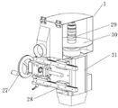
FIG. 3 is a schematic view of the structure at position III in FIG. 2;
FIG. 4 is a schematic view of the structure at position II in FIG. 2;
fig. 5 is a schematic structural diagram of the position I in fig. 2.
Wherein, 1, an operation table; 2. a bed body; 3. positioning the movable guide rail; 4. positioning the telescopic cylinder; 5. positioning a baffle plate; 6. fixing a head pressing part; 7. a movable nose pressing part; 8. cutting the shield; 9. cutting the compression part; 10. a movable machine head; 11. a material rack; 12. a driving motor is fed before and after milling; 13. moving the screw back and forth; 14. milling a pressing support plate by using a section; 15. milling the section; 16. cutting off the saw blade; 17. a saw blade shield; 18. cutting the motor; 19. the cutting tool enters the cylinder; 20. a horizontal milling motor vertical adjusting device; 21. a horizontal milling motor horizontal adjusting device; 22. a horizontal milling motor; 23. horizontally milling the saw blade; 24. a horizontal adjusting device of a vertical milling motor; 25. a vertical milling motor; 26. vertically milling a saw blade; 27. an end milling horizontal adjusting device; 28. a guide rail pair; 29. an end mill cutter adjustment sheet; 30. an end mill; 31. an end milling motor.
I. An end milling unit; II, a reinforcing mullion milling unit; a cleaving unit.
Detailed Description
The technical solutions in the embodiments of the present invention will be described clearly and completely with reference to the accompanying drawings in the embodiments of the present invention, and it is obvious that the described embodiments are only some embodiments of the present invention, not all embodiments. Based on the embodiments in the present invention, all other embodiments obtained by a person skilled in the art without creative work belong to the protection scope of the present invention.
The first embodiment is as follows:
as shown in fig. 1-2, an embodiment of the present invention provides an aluminum-plastic section mullion cutting and milling device, which includes a machine body 2, wherein an operation table 1 is arranged at any side position of the machine body 2, a first platform is arranged at any side position of the upper surface of the machine body 2, a second platform is arranged at a side position of the machine body 2 away from the first platform, a fixed nose pressing portion 6 is arranged at a side position of the first platform close to the second platform, and a movable nose pressing portion 7 is arranged at a side position of the second platform close to the first platform;
a cutting shield 8 is arranged at the position of a second platform, a cutting and pressing part 9 is arranged at the position of the second platform, which is positioned at the cutting shield 8, a material rest 11 is fixedly connected at the position of the second platform, which is far away from the first platform, at one side, a movable machine head 10 is arranged at the position of the material rest 11, an end milling unit I is arranged at the position of the second platform and the first platform, which are positioned at the tail part, a reinforced mullion milling unit II is arranged at the middle position in the second platform and the first platform, and a cutting unit III is arranged at the position of the second platform and the first platform, which is far away from the end milling unit I;
the upper surface of the first platform is fixedly connected with a positioning movable guide rail 3, the upper surface of the first platform is positioned at the positioning movable guide rail 3 and is fixedly connected with a positioning telescopic cylinder 4 through a fixed frame, and the telescopic end of the positioning telescopic cylinder 4 is fixedly connected with a positioning baffle 5;
the positions, close to one side of the end milling unit I, of the second platform and the first platform are fixedly connected with a milling front-back feeding driving motor 12 through a fixing frame, the driving end position of the milling front-back feeding driving motor 12 is fixedly connected with a front-back moving lead screw 13, the front-back moving lead screw 13 is rotatably connected with the side wall of the second platform and the side wall of the first platform, the position of the front-back moving lead screw 13 is connected with a section milling pressing support plate 14 in a penetrating and meshing mode, a movable machine head pressing portion 7 is fixedly connected with the section milling pressing support plate 14, and a milling section 15 is pressed at the driving end position of the movable machine head pressing portion 7.
As shown in fig. 3, the cutting unit III includes a cutting tool feeding cylinder 19, the cutting tool feeding cylinder 19 has a telescopic end facing upward and is fixedly connected with a cutting motor 18, the cutting motor 18 is fixedly connected with a blade guard 17, a cutting blade 16 is arranged in the blade guard 17, and the cutting blade 16 is fixedly connected with a driving end of the cutting motor 18.
As shown in fig. 4, the reinforcing mullion milling unit II comprises a fixed support frame, the fixed support frame is fixedly connected with the corresponding positions of the second platform and the first platform, two horizontal milling motor vertical adjusting devices 20 which are symmetrically arranged are arranged at the positions of the fixed support frame, and a horizontal milling motor horizontal adjusting device 21 and a vertical milling motor horizontal adjusting device 24 are respectively arranged at the slide carriage positions of the two horizontal milling motor vertical adjusting devices 20.
The horizontal milling motor 22 is fixedly connected to the sliding seat position of the horizontal adjusting device 21 of the horizontal milling motor, the vertical milling motor 25 is fixedly connected to the sliding seat position of the horizontal adjusting device 24 of the vertical milling motor, the vertical milling saw blade 26 is fixedly connected to the driving end position of the vertical milling motor 25, and the horizontal milling saw blade 23 is fixedly connected to the driving end position of the horizontal milling motor 22.
As shown in fig. 5, the end milling unit I includes a guide rail pair 28, a slide seat is slidably connected to the guide rail pair 28, the guide rail pair 28 is fixedly connected to the second platform and the first platform, an end milling horizontal adjusting device 27 is disposed at the slide seat, an adjusting screw of the end milling horizontal adjusting device 27 is in threaded connection with the slide seat, an end milling motor 31 is fixedly connected to the slide seat, an end milling cutter adjusting sheet 29 is fixedly connected to a driving end of the end milling motor 31, and an end milling cutter 30 is disposed at the end milling cutter adjusting sheet 29.
The working principle is as follows: the relative positions of a horizontal milling saw blade 23 and a vertical milling saw blade 26 are adjusted by rotating a vertical adjusting device 20 of a horizontal milling motor and a horizontal adjusting device 24 of a vertical milling motor, the position of an end milling cutter 30 is adjusted by an end milling cutter adjusting sheet 29, a milling section 15 is fixed by a movable machine head pressing part 7 and a section milling pressing support plate 14, a driving motor 12 is fed before and after the milling is started, the milling section 15 is moved, the milling section 15 is cut by cutting off a saw blade 16, after the cutting is finished, the section milling pressing support plate 14 is moved to cut the milling section 15 by the horizontal milling saw blade 23 and the vertical milling saw blade 26, and finally, the milling is finished by the end milling cutter 30.
Although embodiments of the present invention have been shown and described, it will be appreciated by those skilled in the art that various changes, modifications, substitutions and alterations can be made in these embodiments without departing from the principles and spirit of the invention, the scope of which is defined in the appended claims and their equivalents.
Claims (8)
1. The utility model provides a club cutting milling equipment in plastic-aluminum section bar, includes lathe bed (2), its characterized in that: a first platform is arranged at any side of the upper surface of the machine body (2), a second platform is arranged at one side of the machine body (2) far away from the first platform, a fixed machine head pressing part (6) is arranged at one side of the first platform close to the second platform, and a movable machine head pressing part (7) is arranged at one side of the second platform close to the first platform;
a cutting shield (8) is arranged at the position of the second platform, a cutting and pressing part (9) is arranged at the position, located on the cutting shield (8), of the second platform, a material rest (11) is fixedly connected to the position, far away from the first platform, of the second platform, a movable machine head (10) is arranged at the position, located on the material rest (11), of the second platform, an end milling unit I is arranged at the position, located at the tail part, of the second platform and the first platform, a reinforcing mullion milling unit II is arranged at the middle position of the second platform and the first platform, and a cutting unit III is arranged at the position, far away from the end milling unit I, of the second platform and the first platform;
the milling machine is characterized in that a milling front-back feeding driving motor (12) is fixedly connected to one side of the second platform and one side of the first platform, which is close to the end milling unit I, through a fixing frame, a front-back moving lead screw (13) is fixedly connected to the driving end position of the milling front-back feeding driving motor (12), the front-back moving lead screw (13) is rotatably connected with the side wall of the second platform and the side wall of the first platform, a section milling pressing support plate (14) is connected to the position of the front-back moving lead screw (13) in a penetrating and meshing mode, a movable machine head pressing part (7) is fixedly connected with the section milling pressing support plate (14), and a milling section (15) is pressed at the driving end position of the movable machine head pressing part (7).
2. The aluminum-plastic profile mullion cutting and milling device according to claim 1, wherein: the cutting unit III comprises a cutting tool feeding cylinder (19), the telescopic end of the cutting tool feeding cylinder (19) faces upwards and is fixedly connected with a cutting motor (18), a saw blade shield (17) is fixedly connected to the position of the cutting motor (18), a cutting saw blade (16) is arranged in the saw blade shield (17), and the cutting saw blade (16) is fixedly connected with the driving end of the cutting motor (18).
3. The aluminum-plastic profile mullion cutting and milling device according to claim 1, wherein: club mills unit II and includes fixing support frame, fixing support frame and second platform and first platform correspond position fixed connection, the fixing support frame position is provided with the level that two symmetries set up and mills motor vertical adjusting device (20), two the slide position that the level milled motor vertical adjusting device (20) position is provided with level respectively and mills motor horizontal adjusting device (21) and mill motor horizontal adjusting device (24) perpendicularly, the slide position fixed connection that the level milled motor horizontal adjusting device (21) has level to mill motor (22), the slide position fixedly connected with that mills motor horizontal adjusting device (24) perpendicularly mills motor (25) perpendicularly.
4. The aluminum-plastic profile mullion cutting and milling device according to claim 3, wherein: the driving end position of the vertical milling motor (25) is fixedly connected with a vertical milling saw blade (26), and the driving end position of the horizontal milling motor (22) is fixedly connected with a horizontal milling saw blade (23).
5. The aluminum-plastic profile mullion cutting and milling device according to claim 1, wherein: the end milling unit I comprises a guide rail pair (28), a slide seat is connected to the guide rail pair (28) in a sliding mode, the guide rail pair (28) is fixedly connected with a second platform and a first platform, an end milling horizontal adjusting device (27) is arranged at the position of the slide seat, an adjusting lead screw of the end milling horizontal adjusting device (27) is connected with the slide seat through threads, and an end milling motor (31) is fixedly connected to the position of the slide seat.
6. The aluminum-plastic profile mullion cutting and milling device according to claim 5, wherein: the end milling machine is characterized in that an end milling cutter adjusting sheet (29) is fixedly connected to the driving end position of the end milling motor (31), and an end milling cutter (30) is arranged at the position of the end milling cutter adjusting sheet (29).
7. The aluminum-plastic profile mullion cutting and milling device according to claim 1, wherein: an operation table (1) is arranged on any side of the lathe bed (2).
8. The aluminum-plastic profile mullion cutting and milling device according to claim 1, wherein: the first platform upper surface position fixedly connected with location movable guide rail (3), first platform upper surface position in location movable guide rail (3) position is through mount fixedly connected with location telescoping cylinder (4), location telescoping cylinder (4) flexible end fixedly connected with location baffle (5).
Priority Applications (1)
| Application Number | Priority Date | Filing Date | Title |
|---|---|---|---|
| CN202221211840.9U CN217344420U (en) | 2022-05-20 | 2022-05-20 | Club cutting milling equipment in plastic-aluminum section bar |
Applications Claiming Priority (1)
| Application Number | Priority Date | Filing Date | Title |
|---|---|---|---|
| CN202221211840.9U CN217344420U (en) | 2022-05-20 | 2022-05-20 | Club cutting milling equipment in plastic-aluminum section bar |
Publications (1)
| Publication Number | Publication Date |
|---|---|
| CN217344420U true CN217344420U (en) | 2022-09-02 |
Family
ID=83013114
Family Applications (1)
| Application Number | Title | Priority Date | Filing Date |
|---|---|---|---|
| CN202221211840.9U Active CN217344420U (en) | 2022-05-20 | 2022-05-20 | Club cutting milling equipment in plastic-aluminum section bar |
Country Status (1)
| Country | Link |
|---|---|
| CN (1) | CN217344420U (en) |
-
2022
- 2022-05-20 CN CN202221211840.9U patent/CN217344420U/en active Active
Similar Documents
| Publication | Publication Date | Title |
|---|---|---|
| CN102390063A (en) | Back loading high-speed computer panel saw | |
| CN108188756B (en) | Glass window section bar preprocessing system | |
| CN213646116U (en) | Novel section bar saw cut machining center | |
| CN218192816U (en) | Double-cutter cutting machine | |
| CN218224910U (en) | Sawing equipment for building aluminum profiles | |
| CN219131113U (en) | Metal plate grooving and shearing compound machine | |
| CN210188687U (en) | Sawing machine for steel processing | |
| CN217344420U (en) | Club cutting milling equipment in plastic-aluminum section bar | |
| CN102259264A (en) | Double-beam planing machine | |
| CN113084884A (en) | Cutting device is used in intention product packaging design | |
| CN110695448B (en) | Plastic-aluminum section bar saw cuts equipment | |
| CN114905282A (en) | Club cutting milling equipment in plastic-aluminum section bar | |
| CN216706644U (en) | Slitting saw with section bar drilling equipment | |
| CN211136232U (en) | Aluminum template processing equipment | |
| CN210525378U (en) | Timber processing platform | |
| CN112846324A (en) | Milling machine head for machining heat-insulation bridge-cut-off aluminum door and window | |
| CN218799903U (en) | Edge cutting device for steel structure machining | |
| CN220480848U (en) | 90-degree cutting and milling machining center for aluminum-plastic section bar | |
| CN216541073U (en) | Numerical control double housing keyway planer that performance of making an uproar is good falls | |
| CN220462442U (en) | 45-degree special cutting saw for aluminum-plastic section bar | |
| CN217316161U (en) | Novel metal cutting machine | |
| CN217393960U (en) | Cutting machine for bevel angle cutting of tooth head | |
| CN218135359U (en) | Cutting station of metal piece of combined frame body | |
| CN218476847U (en) | Double-head grooving machine for building materials | |
| CN214557667U (en) | Milling machine head for machining heat-insulation bridge-cut-off aluminum door and window |
Legal Events
| Date | Code | Title | Description |
|---|---|---|---|
| GR01 | Patent grant | ||
| GR01 | Patent grant |