CN218224910U - Sawing equipment for building aluminum profiles - Google Patents
Sawing equipment for building aluminum profiles Download PDFInfo
- Publication number
- CN218224910U CN218224910U CN202222441434.8U CN202222441434U CN218224910U CN 218224910 U CN218224910 U CN 218224910U CN 202222441434 U CN202222441434 U CN 202222441434U CN 218224910 U CN218224910 U CN 218224910U
- Authority
- CN
- China
- Prior art keywords
- sawing
- fixed
- lifting
- cutting
- angle
- Prior art date
- Legal status (The legal status is an assumption and is not a legal conclusion. Google has not performed a legal analysis and makes no representation as to the accuracy of the status listed.)
- Active
Links
Images


Landscapes
- Sawing (AREA)
Abstract
The utility model provides a sawing device for building aluminum profiles, wherein a conveying device for feeding materials is arranged on the side edge of a frame structure; a vertical sawing device for vertically cutting off the section is arranged right in front of the frame structure; a lifting device is installed inside the rack structure, and a first bevel angle sawing device and a second bevel angle sawing device for sawing a 45-degree angle are fixed at the top of a top plate of the lifting device; and a clamping device used for clamping the section to be sawed is arranged among the first oblique-angle sawing device, the second oblique-angle sawing device and the vertical sawing device. The section sawing equipment adopts a structural design of multiple cutting blades, can finish synchronous or asynchronous saw blades at multiple different parts of a section at one time, and effectively improves the sawing efficiency; and it adopts the arrangement mode that the tool bit is put to the angle of 45 degrees, and the saw cutting shaping at the shaping groove end 45 degrees angles that can be smooth has guaranteed cutting accuracy and quality.
Description
Technical Field
The utility model belongs to the technical field of the construction, especially, relate to a building aluminium alloy saw cuts equipment.
Background
In the process of building construction or building material home decoration, a large amount of aluminum profiles are needed, the aluminum profiles are required to be cut according to different use requirements, and the aluminum profiles are required to be cut into 45-degree angles at corner positions or directly cut off.
Although there is a cutting machine for cutting section bar at present, the cutting machine adopts a structure of single cutting sheet, and can only complete the cutting operation of a single section at one time, and the sawing efficiency is low; in addition, its tool bit mount pad adopts fixed knot to construct, can't carry out the cutting angle regulation of cutting piece, and then can't realize the demand of sawing at 45 degrees angles, in order to carry out the saw cutting at 45 degrees angles, needs the angle of adjustment section bar, and foretell angle regulation process needs the volume to get the section bar and places the angle, probably has saw cutting angular deviation, influences the quality of sawing.
SUMMERY OF THE UTILITY MODEL
In order to solve the technical problems, the utility model provides a sawing device for building aluminum profiles, which adopts the structural design of a plurality of cutting blades, can complete synchronous or asynchronous saw blades at a plurality of different positions of the profiles at one time, and effectively improves the sawing efficiency; the arrangement mode that the cutter head is obliquely arranged at an angle of 45 degrees is adopted, the saw cutting forming of the end head of the groove at an angle of 45 degrees can be smoothly completed, and the cutting precision and quality are ensured; and when 45 degrees of angles are cut, the angles of the section bars do not need to be adjusted, so that the cutting process is simplified, and the safety of cutting operation is ensured.
In order to realize the technical characteristics, the purpose of the utility model is realized as follows: the sawing equipment for the building aluminum profile comprises a rack structure, wherein a conveying device for feeding materials is arranged on the side edge of the rack structure; a vertical sawing device for vertically cutting off the section is arranged in front of the frame structure; a lifting device is installed inside the rack structure, and a first bevel angle sawing device and a second bevel angle sawing device for sawing a 45-degree angle are fixed at the top of a top plate of the lifting device; and a clamping device used for clamping the section to be sawed is arranged among the first oblique-angle sawing device, the second oblique-angle sawing device and the vertical sawing device.
The frame structure comprises a bottom frame body, a top frame body is fixed at the top of the bottom frame body, a top cover is fixed at the top end of the top frame body, and a chip removal box body used for chip blanking is arranged inside the bottom frame body.
The conveying device comprises a conveyor supporting frame, conveying frames are supported at the top of the conveyor supporting frame, and unpowered rollers are arranged between the conveying frames.
The vertical sawing device comprises a first upright column fixed between the frame structures in parallel, a first lifting slide rail is fixed on the outer wall of the first upright column, a first lifting seat is slidably mounted on the first lifting slide rail through a slide block, and a first lifting cylinder body for providing lifting power is mounted between the first lifting seat and the frame structures; the top of first lift seat has motor base through parallel arrangement's horizontal sliding rail slidable mounting, and motor base's top is fixed with first cutting motor, and first saw section is installed to the output shaft of first cutting motor, is provided with between motor base and the first lift seat and saw cuts feed mechanism perpendicularly.
The vertical sawing and feeding mechanism comprises a feeding cylinder body fixed to the top of the first lifting seat, and the tail end of a piston rod of the feeding cylinder body is fixedly connected with the motor base and pushes the motor base to slide along the horizontal sliding rail.
The lifting device comprises a second stand column which is vertically fixed in parallel inside the frame structure, a second lifting slide rail is fixed on the outer wall of the second stand column, a second lifting seat is arranged on the second lifting slide rail in a sliding fit mode through a slide block, a top plate is fixed at the top of the second lifting seat, a second lifting cylinder body is arranged between the second lifting seat and the bottom end of the frame structure, the top plate and the guide stand column form a sliding fit through a guide sliding sleeve, and the guide stand column is vertically fixed inside the frame structure.
The first oblique angle sawing device comprises a second cutting motor fixed at the top of the top plate, an output shaft of the second cutting motor is provided with a first driving belt wheel, the first driving belt wheel is in meshing transmission with a first driven belt wheel through a first belt, the first driven belt wheel is rotatably supported on a first spindle seat through a first spindle, the first spindle seat is fixed at the top of the top plate, and a first oblique-cutting saw blade is fixed at the other end of the first spindle; the first beveling saw blade and the conveying direction of the section bar form an included angle of 45 degrees.
The second bevel angle sawing device comprises a third cutting motor fixed on the top of the top plate, an output shaft of the third cutting motor is provided with a second driving belt wheel, the second driving belt wheel is in meshing transmission with a second driven belt wheel through a second belt, the second driven belt wheel is rotatably supported on a second spindle seat through a second spindle, the second spindle seat is fixed on the top of the top plate, and the other end of the second spindle is fixed with a second beveling saw blade; and the second beveling saw blade forms an included angle of 45 degrees with the conveying direction of the section.
The clamping device comprises a clamping cylinder body fixed on the outer wall of the front face of the rack structure, an L-shaped clamping arm is fixed at the tail end of a piston rod of the clamping cylinder body, the L-shaped clamping arm is matched with a baffle arranged at the edge of the top of the rack structure, and the aluminum profile is fixed between the L-shaped clamping arm and the baffle.
The utility model discloses there is following beneficial effect:
1. the sectional material sawing equipment adopts the structural design of multiple cutting blades, can complete synchronous or asynchronous saw blades at multiple different positions of the sectional material at one time, and effectively improves the sawing efficiency; the arrangement mode that the cutter head is obliquely arranged at an angle of 45 degrees is adopted, the saw cutting forming of the end head of the groove at an angle of 45 degrees can be smoothly completed, and the cutting precision and quality are ensured; and when 45 degrees of angles are cut, the angles of the section bars do not need to be adjusted, so that the cutting process is simplified, and the safety of cutting operation is ensured.
2. The feeding conveying of the sectional materials can be realized through the conveying device, so that the sectional materials to be sawed are sent into the corresponding sawing equipment, and the feeding efficiency is improved.
3. Through foretell perpendicular saw cut device can realize cutting off perpendicularly of section bar, and then guaranteed sectional parallel and level.
4. The feeding of section bar cutting can be realized through the vertical sawing feeding mechanism, and then the cutting-off operation is smoothly completed.
5. Through foretell elevating gear can realize that first oblique angle saw cuts the lift of device and second oblique angle saw cuts the device, and then realize sawing of corresponding oblique terminal surface.
6. Saw cut through foretell first oblique angle saw cut device can realize sawing of oblique terminal surface, and then form 45 contained angles.
7. Saw cutting of oblique terminal surface can be realized through foretell second oblique angle saw cuts the device, and then forms 45 contained angles.
8. Through foretell clamping device can saw cut the in-process, carry out effectual clamp tightly to the section bar, and then guaranteed the security and the reliability of saw cutting the process.
Drawings
The present invention will be further explained with reference to the drawings and examples.
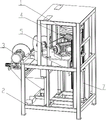
Fig. 1 is a first perspective three-dimensional view of the present invention.
Fig. 2 is a second perspective three-dimensional view of the present invention.
Fig. 3 is a third perspective three-dimensional view of the present invention.
Fig. 4 is a fourth perspective three-dimensional view of the present invention.
In the figure: the device comprises a conveying device 1, a rack structure 2, a vertical sawing device 3, a first oblique sawing device 4, a second oblique sawing device 5, a clamping device 6 and a lifting device 7;
a conveyor support frame 101, an unpowered roller 102 and a conveyor frame 103;
a chip removal box body 201, a bottom frame body 202, a top frame body 203 and a top cover 204;
a first lifting cylinder body 301, a first upright column 302, a first lifting seat 303, a first lifting slide rail 304, a feeding cylinder body 305, a horizontal slide rail 306, a motor base 307, a first saw blade 308 and a first cutting motor 309;
a second cutting motor 401, a first driving pulley 402, a first belt 403, a first beveling saw blade 404, a first driven pulley 405, a first spindle stock 406;
a third cutting motor 501, a second driving pulley 502, a second beveling saw blade 503, a second driven pulley 504 and a second spindle base 505;
the clamping cylinder body 601, the baffle 602 and the L-shaped clamping arm 603;
the lifting device comprises a second upright column 701, a second lifting cylinder body 702, a second lifting slide rail 703, a second lifting seat 704, a guide upright column 705 and a top plate 706.
Detailed Description
The following describes embodiments of the present invention with reference to the drawings.
Referring to fig. 1-4, the sawing device for the building aluminum profiles comprises a frame structure 2, wherein a conveying device 1 for feeding materials is arranged on the side edge of the frame structure 2; a vertical sawing device 3 for vertically cutting off the section is arranged right in front of the frame structure 2; a lifting device 7 is installed inside the frame structure 2, and a first bevel sawing device 4 and a second bevel sawing device 5 for sawing a 45-degree angle are fixed at the top of a top plate 706 of the lifting device 7; and a clamping device 6 for clamping the section to be sawed is arranged among the first oblique-angle sawing device 4, the second oblique-angle sawing device 5 and the vertical sawing device 3. The section sawing equipment adopts a structural design of multiple cutting blades, can finish synchronous or asynchronous saw blades at multiple different parts of a section at one time, and effectively improves the sawing efficiency; the arrangement mode that the cutter head is obliquely arranged at an angle of 45 degrees is adopted, the saw cutting forming of the end head of the groove at an angle of 45 degrees can be smoothly completed, and the cutting precision and quality are ensured; and when carrying out 45 degrees angle cutting, need not to adjust the section bar angle, simplified cutting process, guaranteed the security of cutting operation. In a specific using process, the vertical saw cutting of the section is realized through the vertical saw cutting device 3, so that the vertical cutting of the end face of the section is ensured; the first oblique angle sawing device 4 and the second oblique angle sawing device 5 realize 45-degree angle sawing forming of the end head of the section bar. It is through the structural style who adopts many saw bits, and then effectual its saw cutting efficiency that has improved.
Further, the rack structure 2 includes a bottom frame 202, a top frame 203 is fixed on the top of the bottom frame 202, a top cover 204 is fixed on the top of the top frame 203, and a chip discharging box 201 for discharging chips is arranged inside the bottom frame 202. Through foretell rack construction 2 can be used for carrying out effectual support to whole device, simultaneously, guaranteed the structural strength of whole device.
Further, the conveying device 1 comprises a conveyor supporting frame 101, a conveying frame 103 is supported on the top of the conveyor supporting frame 101, and an unpowered roller 102 is installed between the conveying frames 103. The feeding conveying of the sectional materials can be realized through the conveying device 1, and then the sectional materials to be sawed are sent into the corresponding sawing equipment, so that the feeding efficiency is improved. In a specific use, the profile to be sawn is slidingly transported between the saw blades by means of unpowered rollers 102.
Further, the vertical sawing device 3 comprises a first upright column 302 fixed between the frame structures 2 in parallel, a first lifting slide rail 304 is fixed on the outer wall of the first upright column 302, a first lifting seat 303 is slidably mounted on the first lifting slide rail 304 through a slide block, and a first lifting cylinder 301 for providing lifting power is mounted between the first lifting seat 303 and the frame structures 2; the top of the first lifting seat 303 is provided with a motor base 307 through a horizontal sliding rail 306 which is arranged in parallel in a sliding manner, the top of the motor base 307 is fixed with a first cutting motor 309, an output shaft of the first cutting motor 309 is provided with a first saw blade 308, and a vertical saw cutting feeding mechanism is arranged between the motor base 307 and the first lifting seat 303. The vertical cutting of the section bar can be realized through the vertical saw cutting device 3, and the parallel and level of the section are further ensured. In the specific working process, the whole first lifting seat 303 is driven by the first lifting cylinder body 301 to lift, the first cutting motor 309 at the top of the first lifting cylinder body is driven to lift, the vertical feeding action is realized by the vertical sawing feeding mechanism driving motor base 307, the cutting feeding action is realized, then the first cutting motor 309 is started, the first sawing blade 308 is driven by the first cutting motor 309, and the section bar is cut off by the first sawing blade 308.
Further, the vertical sawing feeding mechanism comprises a feeding cylinder 305 fixed on the top of the first lifting seat 303, and the end of a piston rod of the feeding cylinder 305 is fixedly connected with a motor base 307 and pushes the motor base 307 to slide along a horizontal sliding rail 306. The feeding of section bar cutting can be realized through the vertical sawing feeding mechanism, and then the cutting-off operation can be smoothly completed.
Further, the lifting device 7 includes a second upright column 701 vertically fixed in parallel inside the frame structure 2, a second lifting slide rail 703 is fixed on the outer wall of the second upright column 701, a second lifting seat 704 is slidably fitted on the second lifting slide rail 703 through a slider, a top plate 706 is fixed at the top of the second lifting seat 704, a second lifting cylinder 702 is arranged between the second lifting seat 704 and the bottom end of the frame structure 2, the top plate 706 forms a sliding fit with the guide upright column 705 through a guide sliding sleeve, and the guide upright column 705 is vertically fixed inside the frame structure 2. The lifting device 7 can realize the lifting of the first oblique-angle sawing device 4 and the second oblique-angle sawing device 5, and further realize the sawing of the corresponding oblique end surfaces. In the working process, the second lifting seat 704 is driven by the second lifting cylinder 702, and the second lifting seat 704 is lifted along the second lifting slide rail 703 and the guide upright column 705, so as to drive the corresponding first bevel angle sawing device 4 and the second bevel angle sawing device 5 to lift.
Further, the first bevel sawing device 4 comprises a second cutting motor 401 fixed on the top of the top plate 706, a first driving pulley 402 is mounted on an output shaft of the second cutting motor 401, the first driving pulley 402 is in meshing transmission with a first driven pulley 405 through a first belt 403, the first driven pulley 405 is rotatably supported on a first spindle seat 406 through a first spindle, the first spindle seat 406 is fixed on the top of the top plate 706, and a first beveling saw blade 404 is fixed on the other end of the first spindle; the first miter saw blade 404 is angled at 45 degrees from the direction of the profile. Saw cutting of the inclined end face can be achieved through the first oblique angle saw cutting device 4, and then an included angle of 45 degrees is formed. In the working process, the first driving pulley 402 is driven by the second cutting motor 401, the first driven pulley 405 is driven by the first driving pulley 402 and the first belt 403, the first miter saw blade 404 is driven by the first driven pulley 405, and the profile is sawn by the first miter saw blade 404.
Further, the second bevel sawing device 5 includes a third cutting motor 501 fixed on the top of the top plate 706, a second driving pulley 502 is mounted on an output shaft of the third cutting motor 501, the second driving pulley 502 is in meshing transmission with a second driven pulley 504 through a second belt, the second driven pulley 504 is rotatably supported on a second spindle seat 505 through a second spindle, the second spindle seat 505 is fixed on the top of the top plate 706, and a second bevel saw blade 503 is fixed at the other end of the second spindle; the second beveling saw blade 503 forms an angle of 45 degrees with the profile conveying direction. Saw cutting of the inclined end face can be achieved through the second oblique angle saw cutting device 5, and then an included angle of 45 degrees is formed. In the working process, the third cutting motor 501 drives the second driving pulley 502, the second driving pulley 502 and the second belt drive the second driven pulley 504, the second driven pulley 504 drives the second miter saw blade 503, and the second miter saw blade 503 is used for sawing the profile.
Further, the clamping device 6 comprises a clamping cylinder 601 fixed on the outer wall of the front side of the frame structure 2, an L-shaped clamping arm 603 is fixed at the end of the piston rod of the clamping cylinder 601, the L-shaped clamping arm 603 is matched with a baffle 602 arranged at the top edge of the frame structure 2, and the aluminum profile is fixed between the two. Can carry out effectual clamp to the section bar at saw cutting the in-process through foretell clamping device 6, and then guarantee saw cutting the security and the reliability of process. In the working process, in the sawing process, the section bar is positioned on the baffle 602, then the clamping cylinder 601 is started, the L-shaped clamping arm 603 is driven by the clamping cylinder 601, and the section bar is clamped and fixed on the inner side wall of the baffle 602 through the L-shaped clamping arm 603.
The utility model discloses a working process and principle:
in the process of sawing the section bar, firstly, the section bar to be sawed is conveyed between saw blades through the unpowered roller 102 in a sliding mode, after the conveying length of the section bar is in place, the clamping device 6 is started, the clamping cylinder body 601 drives the L-shaped clamping arm 603, and the section bar is clamped and fixed on the inner side wall of the baffle plate 602 through the L-shaped clamping arm 603; then, selectively starting the first oblique angle sawing device 4, the second oblique angle sawing device 5 or the vertical sawing device 3 according to the type of the end face to be sawed;
when the vertical end face is sawed, the vertical sawing device 3 is started, the whole first lifting seat 303 is driven by the first lifting cylinder body 301 to lift, the first cutting motor 309 at the top of the first lifting seat is driven to lift, the vertical sawing feeding mechanism drives the motor base 307 to realize vertical feeding action, the cutting feeding action is further realized, the first cutting motor 309 is started, the first sawing blade 308 is driven by the first cutting motor 309, the profile is cut off by the first sawing blade 308, and at the moment, the end face of the profile is a vertical end face;
when the end face is sawed, the second lifting base 704 is driven by the second lifting cylinder 702, and the second lifting base 704 lifts along the second lifting slide rail 703 and the guide upright 705, so as to drive the corresponding first bevel sawing device 4 and the second bevel sawing device 5 to lift; then, according to the requirements of the inclination angles of the two ends, selectively starting a first bevel sawing device 4 and a second bevel sawing device 5, driving a first driving pulley 402 through a second cutting motor 401, driving a first driven pulley 405 through the first driving pulley 402 and a first belt 403, driving a first beveling saw blade 404 through the first driven pulley 405, and further sawing the section bar through the first beveling saw blade 404;
a second driving pulley 502 is driven by a third cutting motor 501, a second driven pulley 504 is driven by the second driving pulley 502 and a second belt, a second bevel saw blade 503 is driven by the second driven pulley 504, and the profile is sawn by the second bevel saw blade 503.
Claims (9)
1. Building aluminium alloy saw cuts equipment, its characterized in that: the device comprises a rack structure (2), wherein a conveying device (1) for feeding materials is arranged on the side edge of the rack structure (2); a vertical sawing device (3) for vertically cutting off the section is arranged in front of the frame structure (2); a lifting device (7) is installed inside the rack structure (2), and a first bevel sawing device (4) and a second bevel sawing device (5) for sawing a 45-degree angle are fixed at the top of a top plate (706) of the lifting device (7); and a clamping device (6) for clamping the section to be sawed is arranged among the first oblique-angle sawing device (4), the second oblique-angle sawing device (5) and the vertical sawing device (3).
2. The sawing equipment for the building aluminum profile according to claim 1, characterized in that: frame structure (2) are fixed with top frame body (203) including bottom frame body (202), the top of bottom frame body (202), and the top of top frame body (203) is fixed with top cap (204), and the inside of bottom frame body (202) is provided with chip removal box (201) that are used for the piece unloading.
3. The sawing equipment for the building aluminum profile according to claim 1, characterized in that: the conveying device (1) comprises a conveyor supporting frame (101), conveying frames (103) are supported at the top of the conveyor supporting frame (101), and unpowered rollers (102) are mounted between the conveying frames (103).
4. The sawing equipment for the building aluminum profile according to claim 1, characterized in that: the vertical sawing device (3) comprises first upright columns (302) which are fixed between the rack structures (2) in parallel, first lifting slide rails (304) are fixed on the outer walls of the first upright columns (302), first lifting seats (303) are installed on the first lifting slide rails (304) through sliding blocks in a sliding mode, and first lifting cylinder bodies (301) which provide lifting power are installed between the first lifting seats (303) and the rack structures (2); a motor base (307) is installed at the top of the first lifting seat (303) in a sliding mode through parallel horizontal sliding rails (306), a first cutting motor (309) is fixed to the top of the motor base (307), a first saw blade (308) is installed on an output shaft of the first cutting motor (309), and a vertical saw cutting feeding mechanism is arranged between the motor base (307) and the first lifting seat (303).
5. The sawing equipment for building aluminum profiles according to claim 4, characterized in that: the vertical sawing feeding mechanism comprises a feeding cylinder body (305) fixed to the top of a first lifting seat (303), the tail end of a piston rod of the feeding cylinder body (305) is fixedly connected with a motor base (307), and the motor base (307) is pushed to slide along a horizontal sliding rail (306).
6. The sawing equipment for the building aluminum profile according to claim 1, characterized in that: the lifting device (7) comprises a second upright column (701) which is vertically fixed in parallel inside the rack structure (2), a second lifting slide rail (703) is fixed on the outer wall of the second upright column (701), a second lifting seat (704) is arranged on the second lifting slide rail (703) in a sliding fit mode through a slide block, a top plate (706) is fixed at the top of the second lifting seat (704), a second lifting cylinder body (702) is arranged between the bottom end of the second lifting seat (704) and the bottom end of the rack structure (2), the top plate (706) forms a sliding fit with the guide upright column (705) through a guide slide sleeve, and the guide upright column (705) is vertically fixed inside the rack structure (2).
7. The sawing equipment for the building aluminum profile according to claim 1, characterized in that: the first bevel sawing device (4) comprises a second cutting motor (401) fixed to the top of a top plate (706), a first driving pulley (402) is mounted on an output shaft of the second cutting motor (401), the first driving pulley (402) is in meshing transmission with a first driven pulley (405) through a first belt (403), the first driven pulley (405) is rotatably supported on a first spindle seat (406) through a first spindle, the first spindle seat (406) is fixed to the top of the top plate (706), and a first beveling saw blade (404) is fixed to the other end of the first spindle; the first beveling saw blade (404) forms an included angle of 45 degrees with the conveying direction of the section.
8. The sawing equipment for the building aluminum profile according to claim 1, characterized in that: the second bevel angle sawing device (5) comprises a third cutting motor (501) fixed to the top of a top plate (706), a second driving pulley (502) is mounted on an output shaft of the third cutting motor (501), the second driving pulley (502) is in meshing transmission with a second driven pulley (504) through a second belt, the second driven pulley (504) is rotatably supported on a second spindle seat (505) through a second spindle, the second spindle seat (505) is fixed to the top of the top plate (706), and a second beveling saw blade (503) is fixed to the other end of the second spindle; the second beveling saw blade (503) forms an included angle of 45 degrees with the conveying direction of the section.
9. The sawing equipment for the building aluminum profile according to claim 1, characterized in that: the clamping device (6) comprises a clamping cylinder body (601) fixed on the outer wall of the front face of the rack structure (2), an L-shaped clamping arm (603) is fixed at the tail end of a piston rod of the clamping cylinder body (601), the L-shaped clamping arm (603) is matched with a baffle (602) arranged on the edge of the top of the rack structure (2), and an aluminum profile is fixed between the L-shaped clamping arm and the baffle.
Priority Applications (1)
| Application Number | Priority Date | Filing Date | Title |
|---|---|---|---|
| CN202222441434.8U CN218224910U (en) | 2022-09-15 | 2022-09-15 | Sawing equipment for building aluminum profiles |
Applications Claiming Priority (1)
| Application Number | Priority Date | Filing Date | Title |
|---|---|---|---|
| CN202222441434.8U CN218224910U (en) | 2022-09-15 | 2022-09-15 | Sawing equipment for building aluminum profiles |
Publications (1)
| Publication Number | Publication Date |
|---|---|
| CN218224910U true CN218224910U (en) | 2023-01-06 |
Family
ID=84663170
Family Applications (1)
| Application Number | Title | Priority Date | Filing Date |
|---|---|---|---|
| CN202222441434.8U Active CN218224910U (en) | 2022-09-15 | 2022-09-15 | Sawing equipment for building aluminum profiles |
Country Status (1)
| Country | Link |
|---|---|
| CN (1) | CN218224910U (en) |
Cited By (3)
| Publication number | Priority date | Publication date | Assignee | Title |
|---|---|---|---|---|
| CN116213826A (en) * | 2023-02-16 | 2023-06-06 | 广东福临门世家智能家居有限公司 | Metal cutting device for door and window manufacturing |
| CN116571810A (en) * | 2023-07-14 | 2023-08-11 | 山东辰禾智能装备有限公司 | Sawing device and method for profile with drainage slope |
| CN118237660A (en) * | 2024-04-02 | 2024-06-25 | 广东联仝智能机械有限公司 | Multi-saw blade cutting machine |
-
2022
- 2022-09-15 CN CN202222441434.8U patent/CN218224910U/en active Active
Cited By (5)
| Publication number | Priority date | Publication date | Assignee | Title |
|---|---|---|---|---|
| CN116213826A (en) * | 2023-02-16 | 2023-06-06 | 广东福临门世家智能家居有限公司 | Metal cutting device for door and window manufacturing |
| CN116213826B (en) * | 2023-02-16 | 2023-08-25 | 广东福临门世家智能家居有限公司 | Metal cutting device for door and window manufacturing |
| CN116571810A (en) * | 2023-07-14 | 2023-08-11 | 山东辰禾智能装备有限公司 | Sawing device and method for profile with drainage slope |
| CN116571810B (en) * | 2023-07-14 | 2023-11-03 | 山东辰禾智能装备有限公司 | Sawing device and method for profile with drainage slope |
| CN118237660A (en) * | 2024-04-02 | 2024-06-25 | 广东联仝智能机械有限公司 | Multi-saw blade cutting machine |
Similar Documents
| Publication | Publication Date | Title |
|---|---|---|
| CN218224910U (en) | Sawing equipment for building aluminum profiles | |
| CN108188756B (en) | Glass window section bar preprocessing system | |
| CN213646116U (en) | Novel section bar saw cut machining center | |
| CN206718095U (en) | Chair leg production line | |
| CN106891392A (en) | A kind of new both-end numerical control tenon milling machine | |
| CN210188687U (en) | Sawing machine for steel processing | |
| CN206048520U (en) | Hollow composite board tapping machine | |
| CN213107277U (en) | High-precision double-pushing-handle computer board cutting saw | |
| CN214265958U (en) | Plywood side cut device | |
| CN206718060U (en) | New both-end numerical control tenon milling machine | |
| CN215150683U (en) | Roller adjusting structure of single-wire or multi-wire composite cutting machine | |
| CN214109515U (en) | Aluminum material sawing and milling integrated machine | |
| CN212704742U (en) | Double-station sawing machine | |
| CN213003036U (en) | Sawing device of numerical control sawing machine | |
| CN212094628U (en) | C-shaped steel flying saw shearing equipment in photovoltaic support | |
| CN107856195A (en) | A kind of graphite sawing machine with automatic feeding | |
| CN112338541A (en) | Profile sawing machine | |
| CN217019358U (en) | Efficient machining center for integrated profile sawing and milling | |
| CN217344420U (en) | Club cutting milling equipment in plastic-aluminum section bar | |
| CN2719465Y (en) | Double-frame vertical band saw machine | |
| CN218874436U (en) | Section bar cutting equipment convenient to location | |
| CN221389159U (en) | Arbitrary angle saw cutting device | |
| CN216328849U (en) | Side trimming and grinding device | |
| CN220127741U (en) | Section bar loading attachment and section bar saw cuts system | |
| CN219235736U (en) | Brick cutting machine |
Legal Events
| Date | Code | Title | Description |
|---|---|---|---|
| GR01 | Patent grant | ||
| GR01 | Patent grant |