CN217237420U - Blood smear dyeing frame convenient to locate - Google Patents
Blood smear dyeing frame convenient to locate Download PDFInfo
- Publication number
- CN217237420U CN217237420U CN202221153121.6U CN202221153121U CN217237420U CN 217237420 U CN217237420 U CN 217237420U CN 202221153121 U CN202221153121 U CN 202221153121U CN 217237420 U CN217237420 U CN 217237420U
- Authority
- CN
- China
- Prior art keywords
- dyeing
- plate
- pull rod
- slide
- blood smear
- Prior art date
- Legal status (The legal status is an assumption and is not a legal conclusion. Google has not performed a legal analysis and makes no representation as to the accuracy of the status listed.)
- Active
Links
Images


Landscapes
- Sampling And Sample Adjustment (AREA)
- Investigating Or Analysing Biological Materials (AREA)
Abstract
The utility model discloses a blood smear dyeing rack convenient for positioning, which comprises a dyeing rack body and a dyeing device for dyeing a slide smear, wherein the dyeing device comprises a plurality of division plates arranged on the dyeing rack body, a support frame arranged on the division plates, suckers arranged on the support frame, air guide holes arranged on the suckers, and exhaust tubes communicated with the air guide holes, the utility model solves the problem that the prior blood smear dyeing is often carried out by directly placing a slide on a desktop in the film-making process by arranging the dyeing rack body, the division plates, the support frame, the suckers, the air guide holes, the exhaust tubes, a piston, a pull rod, an anti-falling rod, a limiting plate and a through hole, and easily leads the dyeing agent to flow onto the workbench to pollute the environment, needs one hand to fix the slide during dyeing, and the other hand to carry out smear operation, thus leading the slide to easily shake and shift, the smear staining effect is not ideal, thereby causing a problem that the morphology of the cells is difficult to observe, thereby delaying the time for diagnosis and treatment.
Description
Technical Field
The utility model belongs to the technical field of medical science inspection, especially, relate to a blood smear dyeing frame of convenient location.
Background
In the medical smear inspection process, blood to be detected needs to be evenly smeared on a clean and dry glass slide to prepare a blood smear specimen, and the stained smear is observed and inspected under a microscope, so that the basic method for blood cell morphology inspection can be used for diagnosing various diseases, and the problems in the prior art are as follows: current blood is at the film-making in-process, often directly puts the slide glass and smear the dyeing on the desktop, makes the dyeing agent flow to the workstation easily on, the polluted environment, needs a hand fixed slide glass during the dyeing moreover, and the smear operation is carried out to the other hand, leads to the slide glass to rock the skew easily, and smear dyeing effect is unsatisfactory to lead to being difficult to observe the cell morphology, thereby delays the time of diagnosis treatment.
SUMMERY OF THE UTILITY MODEL
Problem to prior art exists, the utility model provides a blood smear dyeing frame convenient to fix a position, it is convenient to possess to fix the slide, can improve the fixed stability of slide, prevent that the slide skew from rocking, improve dyeing and smear effect, can fix a plurality of slides simultaneously and dye the smear operation, thereby improve the advantage of dyeing smear efficiency, current blood has been solved at the film-making in-process, often directly put slide on the desktop and carry out the smear dyeing, make the dyeing agent flow to the workstation easily, the polluted environment, and need a hand fixed slide during the dyeing, the operation of smearing is carried out to another hand, lead to the slide to rock the skew easily, smear dyeing effect is unsatisfactory, thereby lead to being difficult to observing the cell form, thereby delay the problem of the time of diagnosis treatment.
The utility model is realized in such a way that the blood smear dyeing rack convenient for positioning comprises a dyeing rack body and a dyeing device for dyeing the slide smear, the dyeing device comprises a plurality of partition plates arranged on a dyeing frame body, a support frame arranged on the partition plates, suckers arranged on the support frame, air guide holes arranged on the suckers, exhaust tubes communicated with the air guide holes, pistons arranged in the exhaust tubes, pull rods arranged on the side surfaces of the pistons, anti-falling rods arranged on the pull rods, fixing rods arranged at the bottoms of the suckers, limiting plates arranged on the fixing rods, through holes arranged on the limiting plates and a liquid collecting component for collecting dyeing agents, the piston is connected with the exhaust tube in a sliding way, the pull rod penetrates through the exhaust tube and is connected with the exhaust tube in a sliding way, the pull rod penetrates through the limiting plate and is in sliding connection with the limiting plate, and the anti-falling rod is fixedly connected with the pull rod.
Preferably, the liquid collecting part comprises a filter plate arranged on the dyeing frame body, a liquid collecting cavity arranged in the dyeing frame body, a guide plate arranged in the liquid collecting cavity, a liquid discharge pipe arranged on the dyeing frame body and a disassembling part used for pulling out and cleaning the filter plate, the guide plate is fixedly connected with the bottom surface of the liquid collecting cavity, and the liquid discharge pipe is communicated with the liquid collecting cavity.
Preferably, the disassembling component comprises a sliding groove arranged on the dyeing frame body and a sliding plate arranged inside the sliding groove, the sliding plate is fixedly connected with the filtering plate, and the sliding groove is in sliding connection with the sliding plate.
Preferably, the limiting plate is provided with a limiting groove.
Preferably, the tail end of the pull rod is fixedly provided with an indicating needle, and the indicating needle is perpendicular to the pull rod.
Preferably, a transparent display box is fixedly arranged on the dyeing stand body, and a placing groove is formed in the transparent display box.
Preferably, the side of the filter plate is provided with a waterproof baffle plate, and the waterproof baffle plate is fixedly connected with the filter plate.
Compared with the prior art, the beneficial effects of the utility model are as follows:
1. the utility model discloses a set up staining rack body, division board, support frame, sucking disc, air guide hole, exhaust tube, piston, pull rod, anticreep pole, dead lever, limiting plate and through-hole, reached convenient fixing the slide, can improve the fixed stability of slide, prevent that the slide skew from rocking, improve dyeing and smear effect, can fix a plurality of slides simultaneously and dye the smear operation to improve the effect of dyeing smear efficiency.
2. The utility model discloses a set up filter plate, collection liquid chamber, guide plate and fluid-discharge tube, can flow in a collection liquid intracavity through the filter plate when the dyeing waste liquid is too much to prevent that the dyeing waste liquid from polluting the workstation, collect when full when the dyeing waste liquid of collection liquid intracavity portion, open the fluid-discharge tube, the eminence flow direction fluid-discharge tube discharge of waste liquid through the guide plate, thereby prevent to collect the inside waste liquid of piling up of liquid intracavity portion.
3. The utility model discloses a set up spout and slide, can take off from the dyeing frame body when the filter plate needs clean to the practicality of filter plate body has been improved.
4. The utility model discloses a set up the spacing groove, can make the limiting plate get into the spacing inslot portion to prevent that the limiting plate from deflecting, improve the fixed effect of limiting plate.
5. The utility model discloses a set up the pointer, can judge the position of limiting plate through the pointer, when the pointer is located horizontal position, the limiting plate is located the horizontal direction, and when the pointer is located vertical position, the limiting plate is located vertical direction.
6. The utility model discloses a set up transparent show box and standing groove, can write the patient name that waits to detect on the card, then place the card in the standing groove of transparent show box to when carrying out a plurality of slide staining simultaneously, prevent that the slide is chaotic.
7. The utility model discloses a set up waterproof baffle, can make and prevent that the dyeing waste liquid from flowing through the filter plate to guarantee the good sanitary environment of work area.
Drawings
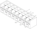
Fig. 1 is a schematic structural diagram provided in an embodiment of the present invention;
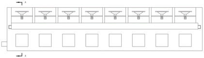
fig. 2 is a front view provided by an embodiment of the present invention;
fig. 3 is a cross-sectional view taken along line a-a of fig. 2 in accordance with an embodiment of the present invention;
fig. 4 is an enlarged view of a portion a in fig. 3 according to an embodiment of the present invention;
fig. 5 is an enlarged view of the point B in fig. 1 according to an embodiment of the present invention;
fig. 6 is a left side view provided by an embodiment of the present invention;
fig. 7 is a cross-sectional view taken along line B-B of fig. 6 according to an embodiment of the present invention.
In the figure: 1. a dyeing rack body; 2. a partition plate; 3. a support frame; 4. a suction cup; 5. an air vent; 6. an air exhaust pipe; 7. a piston; 8. a pull rod; 9. an anti-drop rod; 10. fixing the rod; 11. a limiting plate; 12. a through hole; 13. filtering a plate; 14. a liquid collection cavity; 15. a baffle; 16. a liquid discharge pipe; 17. a chute; 18. a slide plate; 19. a limiting groove; 20. an indicator needle; 21. a transparent display box; 22. a placement groove; 23. waterproof baffle.
Detailed Description
In order to further understand the contents, features and effects of the present invention, the following embodiments are illustrated and described in detail with reference to the accompanying drawings.
The structure of the present invention will be described in detail with reference to the accompanying drawings.
As shown in fig. 1 to 7, an embodiment of the present invention provides a blood smear staining rack convenient for positioning, which comprises a staining rack body 1 and a staining device for staining a slide smear, wherein the staining device comprises a plurality of partition plates 2 arranged on the staining rack body 1, a support frame 3 arranged on the partition plates 2, a suction cup 4 arranged on the support frame 3, an air guide hole 5 arranged on the suction cup 4, an exhaust tube 6 communicated with the air guide hole 5, a piston 7 arranged inside the exhaust tube 6, a pull rod 8 arranged on the side surface of the piston 7, an anti-falling rod 9 arranged on the pull rod 8, a fixing rod 10 arranged at the bottom of the suction cup 4, a limiting plate 11 arranged on the fixing rod 10, a through hole 12 arranged on the limiting plate 11, and a liquid collecting component for collecting a staining agent, wherein the piston 7 is slidably connected with the exhaust tube 6, the pull rod 8 penetrates through the exhaust tube 6 and is slidably connected with the exhaust tube 6, the pull rod 8 penetrates through the limiting plate 11 and is in sliding connection with the limiting plate 11, and the anti-falling rod 9 is fixedly connected with the pull rod 8.
Referring to fig. 3, the liquid collecting part includes a filter plate 13 disposed on the dyeing rack body 1, a liquid collecting cavity 14 disposed inside the dyeing rack body 1, a guide plate 15 disposed inside the liquid collecting cavity 14, a liquid discharging pipe 16 disposed on the dyeing rack body 1, and a detaching part for drawing out and cleaning the filter plate 13, wherein the guide plate 15 is fixedly connected with the bottom surface of the liquid collecting cavity 14, and the liquid discharging pipe 16 is communicated with the liquid collecting cavity 14.
Through setting up filter plate 13, collect liquid chamber 14, guide plate 15 and fluid-discharge tube 16, fluid-discharge tube 16 runs through dyeing frame body 1 and is located guide plate 15 low, can be when dyeing waste liquid is too much, can flow into album liquid chamber 14 through filter plate 13 in, thereby prevent that dyeing waste liquid from polluting the workstation, when collecting when full as the inside dyeing waste liquid in collection liquid chamber 14, open fluid-discharge tube 16, the waste liquid is discharged through guide plate 15's eminence flow direction fluid-discharge tube 16, thereby prevent to collect the inside waste liquid of piling up in liquid chamber 14.
Referring to fig. 7, the detaching member includes a sliding slot 17 disposed on the dyeing frame body 1 and a sliding plate 18 disposed inside the sliding slot 17, the sliding plate 18 is fixedly connected to the filtering plate 13, and the sliding slot 17 is slidably connected to the sliding plate 18.
Through setting up spout 17 and slide 18, slide 18 and filter 13 welding can be when filter plate 13 needs clean, take off from dyeing frame body 1 to the practicality of filter plate 13 body has been improved.
Referring to fig. 5, the limiting plate 11 is provided with a limiting groove 19.
Through setting up spacing groove 19, spacing groove 19 and through-hole 12 mutually perpendicular can make limiting plate 11 get into inside the spacing groove 19 to prevent limiting plate 11 and deflect, improve limiting plate 11's fixed effect.
Referring to fig. 5, an indicator needle 20 is fixedly arranged at the end of the pull rod 8, and the indicator needle 20 is perpendicular to the pull rod 8.
Through setting up pointer 20, pointer 20 bonds with pull rod 8, can judge the position of limiting plate 11 through pointer 20, and when pointer 20 was located horizontal position, limiting plate 11 was located the horizontal direction, and when pointer 20 was located vertical position, limiting plate 11 was located vertical direction.
Referring to fig. 1, a transparent display box 21 is fixedly arranged on the dyeing stand body 1, and a placing groove 22 is arranged in the transparent display box 21.
Through setting up transparent show box 21 and standing groove 22, head and face show box and dyeing frame body 1 bond, can write the patient name that waits to detect on the card, then place the card in transparent show box 21's standing groove 22 to when carrying out a plurality of slide dyeings simultaneously, prevent that the slide is chaotic.
Referring to fig. 3, a waterproof baffle 23 is provided on a side surface of the filter sheet 13.
Through setting up waterproof baffle 23, waterproof baffle 23 and filter plate 13 welding can make and prevent that dyeing waste liquid from flowing through filter plate 13 to guarantee the good sanitary environment of work area.
The utility model discloses a theory of operation:
when in use, firstly, the name of a patient to be detected is written on the card, then the card is placed in the placing groove 22 of the transparent display box 21, so that when a plurality of slides are dyed simultaneously, the slide is prevented from being disordered, then the slide is held by hands, the bottom surface of the slide is placed on the sucking disc 4 and is pressed tightly, then the pull rod 8 is pulled to drive the piston 7 to slide, the volume of the exhaust tube 6 is increased, so that the air guide hole 5 generates negative pressure to adsorb and fix the slide, when the limiting plate 11 completely passes through the through hole 12, the pull rod 8 is rotated, when the indicating needle 20 rotates to the horizontal position, the pull rod 8 is loosened, so that the limiting plate 11 enters the limiting groove 19, so that the limiting plate 11 is prevented from deflecting, then smearing and dyeing operation is carried out on the slide, when too much dyeing waste liquid flows into the liquid collecting cavity 14 through the filter plate 13, so that the dyeing waste liquid is prevented from polluting a workbench, when the dyeing waste liquid in the liquid collecting cavity 14 is fully collected, open fluid-discharge tube 16, the waste liquid flows to fluid-discharge tube 16 through the eminence of guide plate 15 and discharges to prevent that album liquid chamber 14 is inside to pile up the waste liquid, after the coating dyeing finishes, rotate pull rod 8 once more, make indicator 20 be located vertical direction, because the inside atmospheric pressure of exhaust tube 6 is less than atmospheric pressure, piston 7 slides under the effect of atmospheric pressure and resets, thereby makes the inside negative pressure of exhaust tube 6 disappear, sucking disc 4 makes its adsorption effect to the slide, thereby takes off the slide and observes.
In summary, the following steps: this blood smear staining rack convenient to fix a position, through setting up staining rack body 1, division board 2, support frame 3, sucking disc 4, air guide hole 5, exhaust tube 6, piston 7, pull rod 8, anticreep pole 9, dead lever 10, limiting plate 11 and through-hole 12, current blood has been solved at the film-making in-process, often directly put the slide and carry out the smear dyeing on the desktop, make the dyeing agent flow to the workstation easily, the polluted environment, and need a hand fixed slide during the dyeing, another hand carries out the smear operation, it rocks the skew easily to lead to the slide, smear dyeing effect is unsatisfactory, thereby lead to being difficult to observe the cell form, thereby delay the problem of the time of diagnosis treatment.
Claims (7)
1. The utility model provides a convenient blood smear staining rack of location, includes staining rack body (1) and is used for carrying out the dyeing apparatus that slide smear was stained, its characterized in that: the dyeing device comprises a plurality of partition plates (2) arranged on a dyeing frame body (1), a support frame (3) arranged on the partition plates (2), a sucker (4) arranged on the support frame (3), an air guide hole (5) arranged on the sucker (4), an exhaust tube (6) communicated with the air guide hole (5), a piston (7) arranged in the exhaust tube (6), a pull rod (8) arranged on the side surface of the piston (7), an anti-dropping rod (9) arranged on the pull rod (8), a fixed rod (10) arranged at the bottom of the sucker (4), a limiting plate (11) arranged on the fixed rod (10), a through hole (12) arranged on the limiting plate (11) and a liquid collecting part used for collecting a dyeing agent, wherein the piston (7) is in sliding connection with the exhaust tube (6), the pull rod (8) penetrates through the exhaust tube (6) and is in sliding connection with the exhaust tube (6), the pull rod (8) penetrates through the limiting plate (11) and is in sliding connection with the limiting plate (11), the anti-falling rod (9) is fixedly connected with the pull rod (8).
2. A conveniently positionable blood smear staining stand according to claim 1 further comprising: the liquid collecting component comprises a filter plate (13) arranged on the dyeing frame body (1), a liquid collecting cavity (14) arranged inside the dyeing frame body (1), a guide plate (15) arranged inside the liquid collecting cavity (14), a liquid discharging pipe (16) arranged on the dyeing frame body (1) and a disassembling component used for enabling the filter plate (13) to be pulled out and cleaned, wherein the guide plate (15) is fixedly connected with the bottom surface of the liquid collecting cavity (14), and the liquid discharging pipe (16) is communicated with the liquid collecting cavity (14).
3. The conveniently positionable blood smear staining stand of claim 2 further comprising: the disassembling component comprises a sliding groove (17) arranged on the dyeing frame body (1) and a sliding plate (18) arranged inside the sliding groove (17), the sliding plate (18) is fixedly connected with the filtering plate (13), and the sliding groove (17) is in sliding connection with the sliding plate (18).
4. The conveniently positionable blood smear staining stand of claim 1 further comprising: and the limiting plate (11) is provided with a limiting groove (19).
5. The conveniently positionable blood smear staining stand of claim 1 further comprising: the tail end of the pull rod (8) is fixedly provided with an indicating needle (20), and the indicating needle (20) is perpendicular to the pull rod (8).
6. A conveniently positionable blood smear staining stand according to claim 2 further comprising: the dyeing stand is characterized in that a transparent display box (21) is fixedly arranged on the dyeing stand body (1), and a placing groove (22) is formed in the transparent display box (21).
7. The conveniently positionable blood smear staining stand of claim 2 further comprising: and a waterproof baffle (23) is arranged on the side surface of the filter plate (13).
Priority Applications (1)
| Application Number | Priority Date | Filing Date | Title |
|---|---|---|---|
| CN202221153121.6U CN217237420U (en) | 2022-05-13 | 2022-05-13 | Blood smear dyeing frame convenient to locate |
Applications Claiming Priority (1)
| Application Number | Priority Date | Filing Date | Title |
|---|---|---|---|
| CN202221153121.6U CN217237420U (en) | 2022-05-13 | 2022-05-13 | Blood smear dyeing frame convenient to locate |
Publications (1)
| Publication Number | Publication Date |
|---|---|
| CN217237420U true CN217237420U (en) | 2022-08-19 |
Family
ID=82823669
Family Applications (1)
| Application Number | Title | Priority Date | Filing Date |
|---|---|---|---|
| CN202221153121.6U Active CN217237420U (en) | 2022-05-13 | 2022-05-13 | Blood smear dyeing frame convenient to locate |
Country Status (1)
| Country | Link |
|---|---|
| CN (1) | CN217237420U (en) |
Cited By (1)
| Publication number | Priority date | Publication date | Assignee | Title |
|---|---|---|---|---|
| CN115639043A (en) * | 2022-09-26 | 2023-01-24 | 沈阳国科光明医疗科技有限公司 | Automatic multi-linked slice-making and dyeing device |
-
2022
- 2022-05-13 CN CN202221153121.6U patent/CN217237420U/en active Active
Cited By (1)
| Publication number | Priority date | Publication date | Assignee | Title |
|---|---|---|---|---|
| CN115639043A (en) * | 2022-09-26 | 2023-01-24 | 沈阳国科光明医疗科技有限公司 | Automatic multi-linked slice-making and dyeing device |
Similar Documents
| Publication | Publication Date | Title |
|---|---|---|
| CN217237420U (en) | Blood smear dyeing frame convenient to locate | |
| CN209231069U (en) | All-in-one machine is dyed in workbench and film-making with the workbench | |
| CN219021281U (en) | Urine collection and inspection integrated device | |
| CN208621402U (en) | A kind of batch prepares the device of small size filtrate sample | |
| CN208171676U (en) | A kind of sampler for medical inspection | |
| WO2024021222A1 (en) | Exosome extractor | |
| CN208333976U (en) | Food Inspection sampler | |
| WO2023070349A1 (en) | Thrombelastogram instrument | |
| CN208555360U (en) | Polluted water body detects the cleaning device of pipette/direct suction used | |
| CN213209678U (en) | Smear device that clinical medicine inspection used | |
| CN208994199U (en) | A kind of biological detection reagent holder | |
| CN212340768U (en) | Liquid filling device for U-shaped porous glass plate absorption tube | |
| CN108956218B (en) | Slice making clamp for centrifugal liquid-based thin-layer cell slice making machine | |
| CN217505371U (en) | Blood smear pelleter | |
| CN217954038U (en) | Liquid specimen smear device suitable for clinical examination uses | |
| CN206315830U (en) | Novel multi-functional chemical experiment table | |
| CN112871473B (en) | Quick film-making subassembly suitable for horizontal centrifuge | |
| CN218834557U (en) | Quick suction means of test solution | |
| CN209182053U (en) | A kind of pathological specimen sampling plate | |
| CN215985434U (en) | A smear device for clinical laboratory | |
| CN218478746U (en) | Novel nucleic acid sampling tube and tube rack thereof | |
| CN220525843U (en) | Full-automatic blood analyzer sampling equipment | |
| CN108801747A (en) | A kind of batch prepares the device of small size filtrate sample | |
| CN209715177U (en) | A kind of chemical analysis Portable test tube stand | |
| CN213589297U (en) | Endocrine hydrops draw-out device |
Legal Events
| Date | Code | Title | Description |
|---|---|---|---|
| GR01 | Patent grant | ||
| GR01 | Patent grant |