CN216783629U - Vehicle frame front suspension combined support - Google Patents
Vehicle frame front suspension combined support Download PDFInfo
- Publication number
- CN216783629U CN216783629U CN202220489444.6U CN202220489444U CN216783629U CN 216783629 U CN216783629 U CN 216783629U CN 202220489444 U CN202220489444 U CN 202220489444U CN 216783629 U CN216783629 U CN 216783629U
- Authority
- CN
- China
- Prior art keywords
- boss
- mounting plate
- mounting hole
- support
- mounting panel
- Prior art date
- Legal status (The legal status is an assumption and is not a legal conclusion. Google has not performed a legal analysis and makes no representation as to the accuracy of the status listed.)
- Active
Links
Images


Landscapes
- Body Structure For Vehicles (AREA)
Abstract
In order to solve the problem of assembly interference of a cooling module and a steering gear on a vehicle frame, the utility model provides a vehicle frame front suspension combined support which is characterized by comprising a left support, a middle support and a right support, wherein the left support consists of a left mounting plate and a left boss fixedly connected to the left mounting plate, a front cross beam mounting hole is formed in the left boss, the middle support consists of a middle mounting plate, a connecting plate and an outer mounting plate which are sequentially connected from inside to outside, a middle boss is arranged on the middle mounting plate, a cooling module mounting hole is formed in the middle boss, an outer boss is arranged on the outer mounting plate, a steering gear mounting hole is formed in the outer boss, the right support is fixedly connected to the right side of the left support through a connecting rib, the right support consists of a plurality of right bosses, a reinforcing rib is connected between two adjacent right bosses, and a vehicle frame mounting hole is formed in the right boss, the positions of all the components are reasonably arranged, and the weight of the components is reduced.
Description
Technical Field
The utility model relates to the technical field of vehicles, in particular to a front suspension combined bracket of a vehicle frame.
Background
With the development of heavy commercial vehicle technology and the change of market demand, the vehicle chassis arrangement is developing towards the direction of compactness and integration. Under the condition that the configurations of the vehicle wheelbase and the like are the same, the more compact the chassis arrangement and the higher the integration degree are, the larger the available space of the vehicle chassis is, the larger the mountable oil tank is, the more the vehicle chassis can adapt to different upper mountings, and therefore the requirements of different customers can be met; meanwhile, the self weight and the cost of the vehicle are smaller, and the vehicle has more competitive advantages.
However, the air treatment device and the fuel oil coarse filter of the current heavy commercial vehicle are generally dispersedly fixed on the inner side and the outer side of the frame, not only occupy the space of the chassis, but also have relatively large cost and weight by adopting two fixing modes of the bracket, and in addition, the current installation modes of the dispersive arrangement have the problem of inconvenient maintenance more or less.
Disclosure of Invention
In order to solve the problem of assembly interference of a cooling module and a steering gear on a frame, the utility model provides a frame front suspension combined bracket, which adopts the following technical scheme:
the utility model provides a frame front overhang sectional shelf-unit, its characterized in that, includes left socle, middle support and right branch frame, the left socle comprises left mounting panel, the left boss of fixed connection on left mounting panel, be provided with the front beam mounting hole on the boss of a left side, middle support comprises middle mounting panel, connecting plate and the outer mounting panel that from inside to outside connects gradually, be provided with middle boss on the middle mounting panel, be provided with the cooling module mounting hole on the middle boss, be provided with outer boss on the outer mounting panel, be provided with the steering gear mounting hole on the outer boss, the right branch frame passes through splice bar fixed connection in the left socle right side, and the right branch frame comprises a plurality of right bosses, is connected with the strengthening rib between the two adjacent right bosses, be provided with the frame mounting hole on the boss of the right side.
Preferably, the reinforcing ribs and the connecting ribs are of variable cross-section structures.
Preferably, the upper part of the connecting plate is provided with a groove.
Preferably, the inner side surface of the middle mounting plate is provided with a notch which is concave towards the outside.
Preferably, the inner side surface of the middle mounting plate is positioned outside the inner side surface of the right boss.
The utility model has the beneficial effects that: the device integrates the steering gear bracket, the cooling module bracket and the frame front suspension together, thereby not only meeting the requirement of the cooling module on the front wall space, but also realizing the reasonable arrangement of the steering gear, ensuring the installation strength and realizing the weight reduction, and having convenient installation and high maintainability; through the assembly between left socle and the crossbeam, further realize controlling the connection of frame front overhang through the crossbeam, improve its torsional capacity.
Drawings
FIG. 1 is a schematic structural view of the present invention;
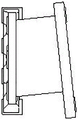
FIG. 2 is a front view of FIG. 1;
FIG. 3 is a left side view of FIG. 1;
FIG. 4 is a top view of FIG. 1;
the automobile steering wheel comprises a left support 1, a left mounting plate 11, a left boss 12, a front cross beam mounting hole 13, a middle support 2, a middle mounting plate 21, a connecting plate 22, an outer mounting plate 23, a middle boss 211, a cooling module mounting hole 212, a notch 213, a groove 221, an outer boss 231, a steering gear mounting hole 232, a connecting rib 3, a right support 4, a right boss 41, a frame mounting hole 42 and a reinforcing rib 43.
Detailed Description
Exemplary embodiments of the present disclosure will be described in more detail below with reference to the accompanying drawings. While exemplary embodiments of the present disclosure are shown in the drawings, it should be understood that the present disclosure may be embodied in various forms and should not be limited to the embodiments set forth herein. Rather, these embodiments are provided so that this disclosure will be thorough and complete, and will fully convey the scope of the disclosure to those skilled in the art.
In the description of the present invention, it is to be understood that the terms "longitudinal", "lateral", "up", "down", "front", "back", "left", "right", "vertical", "horizontal", "top", "bottom", "inner", "outer", and the like indicate orientations or positional relationships based on those shown in the drawings, and are only for convenience of description of the present invention, and do not indicate or imply that the device or element so referred to must have a particular orientation, be constructed and operated in a particular orientation, and therefore, should not be construed as limiting the present invention.
The frame front suspension combined bracket shown in fig. 1-4 comprises a left bracket 1, a middle bracket 2 and a right bracket 4, wherein the left bracket 1 comprises a left mounting plate 11, a plurality of left bosses 12 are fixedly arranged on the left mounting plate 11, front cross beam mounting holes 13 are arranged on the left bosses 12, and the left bosses 12 are fixedly connected with a front cross beam through bolts after the left bosses 12 are attached to the front cross beam; the middle bracket 2 comprises a middle mounting plate 21, a connecting plate 22 and an outer mounting plate 23 which are connected in sequence from inside to outside, the middle mounting plate 21 is fixedly connected with the right side of the left mounting plate 11, four middle bosses 211 are arranged on the middle mounting plate 21, cooling module mounting holes 212 are arranged on the middle bosses 211 for mounting cooling modules, notches 213 are arranged among the four middle bosses 211 for preventing the cooling modules from interference during mounting, the connecting plate 22 is fixedly connected with the middle mounting plate 21, the groove 221 is formed in the upper left corner of the connecting plate 22, installation space is provided for a connecting bolt between the steering gear and the outer mounting plate 23, the steering gear is convenient to install, the outer mounting plate 23 is fixedly connected with the connecting plate 22, an outer boss 231 is arranged on the outer side face of the outer mounting plate 23, a steering gear installation hole 232 used for installing the steering gear is formed in the outer boss 231, and a certain included angle is formed between the outer mounting plate 23 and the middle mounting plate 21; the right branch frame 4 includes a plurality of right bosss 41, is provided with frame mounting hole 42 on the boss 41 of the right side, and links to each other through strengthening rib 43 is fixed between two adjacent right bosss 41, and right branch frame 4 wholly is frame construction, and the left side is through the middle mounting panel 21 fixed connection of splice bar 3 with middle support 2 to the upper portion position at the middle part of right branch frame 4 is provided with the diamond hole, avoids interfering with other parts.
In addition, the reinforcing ribs 43 and the connecting ribs 3 are of a variable cross-section structure, so that the weight of the component is reduced, and the inner side surface of the middle mounting plate 21 is positioned outside the inner side surface of the right boss 41, so that enough space is provided for mounting the cooling module.
The above description is only of the preferred embodiments of the present invention, and it should be noted that: it will be apparent to those skilled in the art that various modifications can be made without departing from the principles of the utility model and these modifications are to be considered within the scope of the utility model.
Claims (5)
1. The utility model provides a frame front overhang sectional shelf-unit, its characterized in that, includes left socle, middle support and right branch frame, the left socle comprises left mounting panel, the left boss of fixed connection on left mounting panel, be provided with the front beam mounting hole on the boss of a left side, middle support comprises middle mounting panel, connecting plate and the outer mounting panel that from inside to outside connects gradually, be provided with middle boss on the middle mounting panel, be provided with the cooling module mounting hole on the middle boss, be provided with outer boss on the outer mounting panel, be provided with the steering gear mounting hole on the outer boss, the right branch frame passes through splice bar fixed connection in the left socle right side, and the right branch frame comprises a plurality of right bosses, is connected with the strengthening rib between the two adjacent right bosses, be provided with the frame mounting hole on the boss of the right side.
2. The vehicle frame front suspension combination bracket according to claim 1, characterized in that the reinforcing ribs and the connecting ribs are of variable cross-section structures.
3. The front suspension bracket of claim 1, characterized in that the upper part of the connecting plate is provided with a groove.
4. The front suspension assembly bracket of claim 1, wherein the inner side surface of the middle mounting plate is provided with an outwardly concave recess.
5. The front suspension combination bracket of claim 1, characterized in that the inner side surface of the middle mounting plate is positioned outside the inner side surface of the right boss.
Priority Applications (1)
| Application Number | Priority Date | Filing Date | Title |
|---|---|---|---|
| CN202220489444.6U CN216783629U (en) | 2022-03-09 | 2022-03-09 | Vehicle frame front suspension combined support |
Applications Claiming Priority (1)
| Application Number | Priority Date | Filing Date | Title |
|---|---|---|---|
| CN202220489444.6U CN216783629U (en) | 2022-03-09 | 2022-03-09 | Vehicle frame front suspension combined support |
Publications (1)
| Publication Number | Publication Date |
|---|---|
| CN216783629U true CN216783629U (en) | 2022-06-21 |
Family
ID=81999869
Family Applications (1)
| Application Number | Title | Priority Date | Filing Date |
|---|---|---|---|
| CN202220489444.6U Active CN216783629U (en) | 2022-03-09 | 2022-03-09 | Vehicle frame front suspension combined support |
Country Status (1)
| Country | Link |
|---|---|
| CN (1) | CN216783629U (en) |
-
2022
- 2022-03-09 CN CN202220489444.6U patent/CN216783629U/en active Active
Similar Documents
| Publication | Publication Date | Title |
|---|---|---|
| KR20090064307A (en) | Battery unit mounting structure for electric vehicle | |
| US20020024191A1 (en) | Steering gear frame | |
| CN111634248A (en) | Suspension structure and device for mounting parts of power assembly of electric automobile | |
| CN216783629U (en) | Vehicle frame front suspension combined support | |
| CN210454955U (en) | Combined support crossbeam | |
| CN218967018U (en) | Frame for electric tractor and electric tractor | |
| CN115416468A (en) | Power battery mounting structure, frame assembly and new energy commercial car | |
| CN216783630U (en) | Integrated fixed bolster | |
| CN216002542U (en) | Integrated mounting bracket assembly of electric vehicle | |
| JPH1178552A (en) | Supporting device for bus fuel tank | |
| CN217804902U (en) | Installing support, frame front end assembly and vehicle | |
| CN216993816U (en) | Air conditioner installing support and hybrid power wide-body vehicle | |
| CN214874089U (en) | Plate spring support and tubular cross beam combined structure for truck | |
| CN220518426U (en) | Cab rear suspension bracket | |
| CN220947560U (en) | Rear suspension assembly of engine | |
| CN210116551U (en) | Rear auxiliary frame and vehicle | |
| CN221023245U (en) | Walking motor mounting structure | |
| CN218021894U (en) | Support frame | |
| CN220640009U (en) | Modularized integrated mounting structure for vehicle and light truck | |
| CN216915460U (en) | Air condition compressor and passenger door activity integrated installation device that marks time | |
| CN219947814U (en) | Multi-interface oil cylinder bracket for oil-gas front suspension of mining dump truck | |
| CN215826837U (en) | Rear suspension beam structure and vehicle | |
| CN213472805U (en) | Vehicle body structure and vehicle | |
| CN209224923U (en) | Vehicle and its expansion tank bracket | |
| CN216034651U (en) | Auxiliary frame and vehicle |
Legal Events
| Date | Code | Title | Description |
|---|---|---|---|
| GR01 | Patent grant | ||
| GR01 | Patent grant |