CN111634248A - Mounting structure and device for mounting components of electric vehicle powertrain - Google Patents
Mounting structure and device for mounting components of electric vehicle powertrain Download PDFInfo
- Publication number
- CN111634248A CN111634248A CN202010393832.XA CN202010393832A CN111634248A CN 111634248 A CN111634248 A CN 111634248A CN 202010393832 A CN202010393832 A CN 202010393832A CN 111634248 A CN111634248 A CN 111634248A
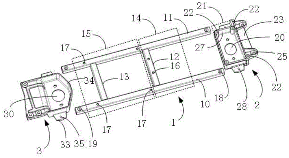
- Authority
- CN
- China
- Prior art keywords
- mounting
- suspension bracket
- suspension
- stretcher
- electric vehicle
- Prior art date
- Legal status (The legal status is an assumption and is not a legal conclusion. Google has not performed a legal analysis and makes no representation as to the accuracy of the status listed.)
- Pending
Links
- 239000000725 suspension Substances 0.000 claims abstract description 212
- 230000003014 reinforcing effect Effects 0.000 claims description 5
- 230000006978 adaptation Effects 0.000 claims 1
- 230000000149 penetrating effect Effects 0.000 claims 1
- 238000009434 installation Methods 0.000 abstract description 85
- 238000000034 method Methods 0.000 description 17
- 239000000446 fuel Substances 0.000 description 15
- 238000010586 diagram Methods 0.000 description 8
- 230000008569 process Effects 0.000 description 6
- 230000008901 benefit Effects 0.000 description 4
- 230000000694 effects Effects 0.000 description 3
- 230000002787 reinforcement Effects 0.000 description 3
- 238000010521 absorption reaction Methods 0.000 description 1
- XAGFODPZIPBFFR-UHFFFAOYSA-N aluminium Chemical compound [Al] XAGFODPZIPBFFR-UHFFFAOYSA-N 0.000 description 1
- 229910052782 aluminium Inorganic materials 0.000 description 1
- 230000009286 beneficial effect Effects 0.000 description 1
- 238000005266 casting Methods 0.000 description 1
- 230000008859 change Effects 0.000 description 1
- 238000006243 chemical reaction Methods 0.000 description 1
- 239000003638 chemical reducing agent Substances 0.000 description 1
- 238000009826 distribution Methods 0.000 description 1
- 238000004519 manufacturing process Methods 0.000 description 1
- 238000012986 modification Methods 0.000 description 1
- 230000004048 modification Effects 0.000 description 1
Images


Classifications
-
- B—PERFORMING OPERATIONS; TRANSPORTING
- B60—VEHICLES IN GENERAL
- B60R—VEHICLES, VEHICLE FITTINGS, OR VEHICLE PARTS, NOT OTHERWISE PROVIDED FOR
- B60R16/00—Electric or fluid circuits specially adapted for vehicles and not otherwise provided for; Arrangement of elements of electric or fluid circuits specially adapted for vehicles and not otherwise provided for
- B60R16/02—Electric or fluid circuits specially adapted for vehicles and not otherwise provided for; Arrangement of elements of electric or fluid circuits specially adapted for vehicles and not otherwise provided for electric constitutive elements
- B60R16/04—Arrangement of batteries
-
- B—PERFORMING OPERATIONS; TRANSPORTING
- B60—VEHICLES IN GENERAL
- B60K—ARRANGEMENT OR MOUNTING OF PROPULSION UNITS OR OF TRANSMISSIONS IN VEHICLES; ARRANGEMENT OR MOUNTING OF PLURAL DIVERSE PRIME-MOVERS IN VEHICLES; AUXILIARY DRIVES FOR VEHICLES; INSTRUMENTATION OR DASHBOARDS FOR VEHICLES; ARRANGEMENTS IN CONNECTION WITH COOLING, AIR INTAKE, GAS EXHAUST OR FUEL SUPPLY OF PROPULSION UNITS IN VEHICLES
- B60K1/00—Arrangement or mounting of electrical propulsion units
-
- B—PERFORMING OPERATIONS; TRANSPORTING
- B60—VEHICLES IN GENERAL
- B60K—ARRANGEMENT OR MOUNTING OF PROPULSION UNITS OR OF TRANSMISSIONS IN VEHICLES; ARRANGEMENT OR MOUNTING OF PLURAL DIVERSE PRIME-MOVERS IN VEHICLES; AUXILIARY DRIVES FOR VEHICLES; INSTRUMENTATION OR DASHBOARDS FOR VEHICLES; ARRANGEMENTS IN CONNECTION WITH COOLING, AIR INTAKE, GAS EXHAUST OR FUEL SUPPLY OF PROPULSION UNITS IN VEHICLES
- B60K17/00—Arrangement or mounting of transmissions in vehicles
- B60K17/04—Arrangement or mounting of transmissions in vehicles characterised by arrangement, location or kind of gearing
- B60K17/06—Arrangement or mounting of transmissions in vehicles characterised by arrangement, location or kind of gearing of change-speed gearing
-
- B—PERFORMING OPERATIONS; TRANSPORTING
- B60—VEHICLES IN GENERAL
- B60L—PROPULSION OF ELECTRICALLY-PROPELLED VEHICLES; SUPPLYING ELECTRIC POWER FOR AUXILIARY EQUIPMENT OF ELECTRICALLY-PROPELLED VEHICLES; ELECTRODYNAMIC BRAKE SYSTEMS FOR VEHICLES IN GENERAL; MAGNETIC SUSPENSION OR LEVITATION FOR VEHICLES; MONITORING OPERATING VARIABLES OF ELECTRICALLY-PROPELLED VEHICLES; ELECTRIC SAFETY DEVICES FOR ELECTRICALLY-PROPELLED VEHICLES
- B60L15/00—Methods, circuits, or devices for controlling the traction-motor speed of electrically-propelled vehicles
-
- B—PERFORMING OPERATIONS; TRANSPORTING
- B60—VEHICLES IN GENERAL
- B60L—PROPULSION OF ELECTRICALLY-PROPELLED VEHICLES; SUPPLYING ELECTRIC POWER FOR AUXILIARY EQUIPMENT OF ELECTRICALLY-PROPELLED VEHICLES; ELECTRODYNAMIC BRAKE SYSTEMS FOR VEHICLES IN GENERAL; MAGNETIC SUSPENSION OR LEVITATION FOR VEHICLES; MONITORING OPERATING VARIABLES OF ELECTRICALLY-PROPELLED VEHICLES; ELECTRIC SAFETY DEVICES FOR ELECTRICALLY-PROPELLED VEHICLES
- B60L53/00—Methods of charging batteries, specially adapted for electric vehicles; Charging stations or on-board charging equipment therefor; Exchange of energy storage elements in electric vehicles
- B60L53/20—Methods of charging batteries, specially adapted for electric vehicles; Charging stations or on-board charging equipment therefor; Exchange of energy storage elements in electric vehicles characterised by converters located in the vehicle
- B60L53/22—Constructional details or arrangements of charging converters specially adapted for charging electric vehicles
-
- Y—GENERAL TAGGING OF NEW TECHNOLOGICAL DEVELOPMENTS; GENERAL TAGGING OF CROSS-SECTIONAL TECHNOLOGIES SPANNING OVER SEVERAL SECTIONS OF THE IPC; TECHNICAL SUBJECTS COVERED BY FORMER USPC CROSS-REFERENCE ART COLLECTIONS [XRACs] AND DIGESTS
- Y02—TECHNOLOGIES OR APPLICATIONS FOR MITIGATION OR ADAPTATION AGAINST CLIMATE CHANGE
- Y02T—CLIMATE CHANGE MITIGATION TECHNOLOGIES RELATED TO TRANSPORTATION
- Y02T10/00—Road transport of goods or passengers
- Y02T10/60—Other road transportation technologies with climate change mitigation effect
- Y02T10/70—Energy storage systems for electromobility, e.g. batteries
-
- Y—GENERAL TAGGING OF NEW TECHNOLOGICAL DEVELOPMENTS; GENERAL TAGGING OF CROSS-SECTIONAL TECHNOLOGIES SPANNING OVER SEVERAL SECTIONS OF THE IPC; TECHNICAL SUBJECTS COVERED BY FORMER USPC CROSS-REFERENCE ART COLLECTIONS [XRACs] AND DIGESTS
- Y02—TECHNOLOGIES OR APPLICATIONS FOR MITIGATION OR ADAPTATION AGAINST CLIMATE CHANGE
- Y02T—CLIMATE CHANGE MITIGATION TECHNOLOGIES RELATED TO TRANSPORTATION
- Y02T10/00—Road transport of goods or passengers
- Y02T10/60—Other road transportation technologies with climate change mitigation effect
- Y02T10/7072—Electromobility specific charging systems or methods for batteries, ultracapacitors, supercapacitors or double-layer capacitors
-
- Y—GENERAL TAGGING OF NEW TECHNOLOGICAL DEVELOPMENTS; GENERAL TAGGING OF CROSS-SECTIONAL TECHNOLOGIES SPANNING OVER SEVERAL SECTIONS OF THE IPC; TECHNICAL SUBJECTS COVERED BY FORMER USPC CROSS-REFERENCE ART COLLECTIONS [XRACs] AND DIGESTS
- Y02—TECHNOLOGIES OR APPLICATIONS FOR MITIGATION OR ADAPTATION AGAINST CLIMATE CHANGE
- Y02T—CLIMATE CHANGE MITIGATION TECHNOLOGIES RELATED TO TRANSPORTATION
- Y02T10/00—Road transport of goods or passengers
- Y02T10/60—Other road transportation technologies with climate change mitigation effect
- Y02T10/72—Electric energy management in electromobility
-
- Y—GENERAL TAGGING OF NEW TECHNOLOGICAL DEVELOPMENTS; GENERAL TAGGING OF CROSS-SECTIONAL TECHNOLOGIES SPANNING OVER SEVERAL SECTIONS OF THE IPC; TECHNICAL SUBJECTS COVERED BY FORMER USPC CROSS-REFERENCE ART COLLECTIONS [XRACs] AND DIGESTS
- Y02—TECHNOLOGIES OR APPLICATIONS FOR MITIGATION OR ADAPTATION AGAINST CLIMATE CHANGE
- Y02T—CLIMATE CHANGE MITIGATION TECHNOLOGIES RELATED TO TRANSPORTATION
- Y02T90/00—Enabling technologies or technologies with a potential or indirect contribution to GHG emissions mitigation
- Y02T90/10—Technologies relating to charging of electric vehicles
- Y02T90/14—Plug-in electric vehicles
Landscapes
- Engineering & Computer Science (AREA)
- Mechanical Engineering (AREA)
- Transportation (AREA)
- Power Engineering (AREA)
- Chemical & Material Sciences (AREA)
- Combustion & Propulsion (AREA)
- Arrangement Or Mounting Of Propulsion Units For Vehicles (AREA)
- Body Structure For Vehicles (AREA)
Abstract
本申请涉及一种用于安装电动汽车动力总成各零部件的悬置结构及装置,其包括左悬置支架、右悬置支架和担架型梁;左悬置支架用于与左前纵梁刚性相连,其上设有用于与左悬置臂柔性连接的第一安装孔;右悬置支架用于与右前纵梁刚性相连,其上设有用于与右悬置臂柔性连接的第二安装孔;担架型梁两端分别与所述左悬置支架和右悬置支架刚性相连,所述担架型梁上设有用于安装PTC加热器的第一安装区和用于安装电机控制器、车载充电机及DC/DC转换器的第二安装区;以及,所述左悬置支架或右悬置支架上设有用于安装蓄电池的第三安装区。本申请可以解决相关技术中电机、变速箱的振动会对电机控制器、车载充电机、DC\DC转换器等零部件造成影响的问题。
The present application relates to a suspension structure and device for installing various components of an electric vehicle powertrain, which includes a left suspension bracket, a right suspension bracket and a stretcher beam; the left suspension bracket is used for rigidity with the left front longitudinal beam connected with the left suspension arm, which is provided with a first installation hole for flexible connection with the left suspension arm; the right suspension bracket is used for rigid connection with the right front longitudinal beam, and is provided with a second installation hole for flexible connection with the right suspension arm The two ends of the stretcher beam are rigidly connected with the left suspension bracket and the right suspension bracket respectively, and the stretcher beam is provided with a first installation area for installing a PTC heater and a first installation area for installing a motor controller, on-board charging a second installation area for the generator and the DC/DC converter; and a third installation area for installing the battery is provided on the left or right suspension bracket. The present application can solve the problem in the related art that the vibration of the motor and the gearbox will affect components such as the motor controller, the on-board charger, and the DC/DC converter.
Description
技术领域technical field
本申请涉及乘用车动力总成技术领域,特别涉及一种用于安装电动汽车动力总成各零部件的悬置结构及装置。The present application relates to the technical field of passenger vehicle powertrains, and in particular, to a suspension structure and a device for installing various components of an electric vehicle powertrain.
背景技术Background technique
传统燃油汽车的动力总成主要是由发动机、变速箱构成的总成,多采用三点式悬置。而电动汽车的动力总成除了包括由电机和变速箱构成的总成件之外,还包括电机控制器、车载充电机、DC\DC转换器及PTC加热器等零部件,故电动汽车的动力总成在装配时与传统燃油汽车存在一些不同,并不能完全按照传统燃油汽车的装配方式进行安装。The powertrain of a traditional fuel vehicle is mainly composed of an engine and a gearbox, mostly using a three-point mount. In addition to the assembly composed of the motor and the gearbox, the powertrain of an electric vehicle also includes parts such as a motor controller, an on-board charger, a DC/DC converter, and a PTC heater. There are some differences in the assembly of the assembly from traditional fuel vehicles, and it cannot be installed exactly in the way of traditional fuel vehicles.
在一些方案中,将电机控制器、车载充电机、DC\DC转换器及PTC加热器等零部件直接固定在车身上,该方案存在车身固定点过多的弊端。In some solutions, components such as motor controllers, on-board chargers, DC/DC converters, and PTC heaters are directly fixed on the body, which has the disadvantage of too many fixing points on the body.
在另一些方案中,提供动力总成支架,该动力总成支架包括支撑框架以及两端分别连接的左支架梁和右支架梁,电机和减速器作为整体两端分别连接在左支架梁和右支架梁底端,电机控制器、DC\DC转换器固定在支撑框架底部,而车载充电机、配电箱固定在支撑框架顶部,上述所有部件构成整体,且左右两端分别连接左悬置和右悬置。上述方案即是将各零部件捆绑到一起采用三点式悬置,虽然可以减少车身固定点,但采用这种方式时,电机、变速箱的振动就会对电机控制器、车载充电机、DC\DC转换器等零部件造成影响。In other solutions, a powertrain support is provided, the powertrain support includes a support frame and a left support beam and a right support beam respectively connected at both ends, and the motor and the reducer as a whole are connected at both ends to the left support beam and the right support beam respectively. At the bottom of the support beam, the motor controller and DC\DC converter are fixed at the bottom of the support frame, while the on-board charger and power distribution box are fixed at the top of the support frame. All the above components form a whole, and the left and right ends are respectively connected to the left suspension and Right suspension. The above solution is to bundle the parts together and use a three-point mount. Although the fixed points of the body can be reduced, the vibration of the motor and gearbox will affect the motor controller, on-board charger, DC\DC in this way. Components such as converters are affected.
此外,还要考虑“油改电”车型的动力总成固定点与燃油车的通用性。若要实现该种情形的固定方式,并且达到易于安装和拆卸,又能达到低成本就是一个技术难题。In addition, the commonality of the fixed point of the powertrain of the "oil-to-electricity" model and the fuel vehicle should also be considered. It is a technical problem to realize the fixing method of this kind of situation, and to achieve easy installation and disassembly, and also to achieve low cost.
发明内容SUMMARY OF THE INVENTION
本申请实施例提供一种用于安装电动汽车动力总成各零部件的悬置结构及装置,以解决相关技术中电机、变速箱的振动会对电机控制器、车载充电机、DC\DC转换器等零部件造成影响的问题。The embodiment of the present application provides a suspension structure and device for installing various components of an electric vehicle powertrain, so as to solve the problem that the vibration of the motor and the gearbox in the related art will affect the motor controller, the on-board charger, and the DC/DC conversion. problems caused by components such as the device.
第一方面,提供了一种用于安装电动汽车动力总成各零部件的悬置结构,其包括:In a first aspect, a suspension structure for installing components of an electric vehicle powertrain is provided, which includes:
用于与左前纵梁刚性相连的左悬置支架,其上设有用于与左悬置臂柔性连接的第一安装孔;a left suspension bracket for rigidly connecting with the left front longitudinal beam, and a first mounting hole for flexible connection with the left suspension arm;
用于与右前纵梁刚性相连的右悬置支架,其上设有用于与右悬置臂柔性连接的第二安装孔;a right suspension bracket for rigidly connecting with the right front longitudinal beam, and a second mounting hole for flexible connection with the right suspension arm;
担架型梁,其两端分别与所述左悬置支架和右悬置支架刚性相连,所述担架型梁上设有用于安装PTC加热器的第一安装区和用于安装电机控制器、车载充电机及DC/DC转换器的第二安装区;以及,The stretcher beam is rigidly connected with the left suspension bracket and the right suspension bracket at both ends, and the stretcher beam is provided with a first installation area for installing the PTC heater and a first installation area for installing the motor controller, the vehicle a second mounting area for the charger and DC/DC converter; and,
所述左悬置支架或右悬置支架上设有用于安装蓄电池的第三安装区。The left suspension bracket or the right suspension bracket is provided with a third installation area for installing the battery.
一些实施例中,所述担架型梁包括前横梁、后横梁,以及沿前横梁或后横梁长度方向间隔布置的左连接梁和右连接梁;In some embodiments, the stretcher beam includes a front beam, a rear beam, and a left connecting beam and a right connecting beam spaced along the length of the front beam or the rear beam;
所述左连接梁两端分别与前横梁、后横梁相连,并围合形成有所述第一安装区;Both ends of the left connecting beam are respectively connected with the front beam and the rear beam, and enclose the first installation area;
所述右连接梁两端分别与前横梁、后横梁相连,并围合形成有所述第二安装区。The two ends of the right connecting beam are respectively connected with the front beam and the rear beam, and the second installation area is formed by enclosing them.
一些实施例中,于第一安装区内,在左连接梁上设有用于安装PTC加热器的第三安装孔;In some embodiments, in the first installation area, a third installation hole for installing the PTC heater is provided on the left connecting beam;
于第二安装区内,在前横梁和后横梁上设有用于安装电机控制器、车载充电机及DC/DC转换器的第四安装孔。In the second installation area, the front beam and the rear beam are provided with fourth installation holes for installing the motor controller, the vehicle charger and the DC/DC converter.
一些实施例中,该悬置结构还包括箱体,所述箱体组设于第二安装区,并用于安装电机控制器、车载充电机及DC/DC转换器。In some embodiments, the suspension structure further includes a box, and the box set is arranged in the second installation area and used for installing the motor controller, the vehicle charger and the DC/DC converter.
一些实施例中,当所述左悬置支架上设有第三安装区时,于第三安装区内,在所述左悬置支架上设有若干用于安装蓄电池的第五安装孔;In some embodiments, when the left suspension bracket is provided with a third installation area, in the third installation area, a plurality of fifth installation holes for installing batteries are provided on the left suspension bracket;
当所述右悬置支架上设有第三安装区时,于第三安装区内,在所述右悬置支架上设有若干用于安装蓄电池的第五安装孔。When the right suspension bracket is provided with a third installation area, in the third installation area, a plurality of fifth installation holes for installing batteries are provided on the right suspension bracket.
一些实施例中,所述左悬置支架远离担架型梁的一侧形成有第一连接部,所述第一连接部用于刚性连接于左前纵梁顶面;In some embodiments, a first connecting portion is formed on a side of the left suspension bracket away from the stretcher beam, and the first connecting portion is used for rigidly connecting to the top surface of the left front longitudinal beam;
所述左悬置支架底部形成有第二连接部,所述第二连接部用于刚性连接于左前纵梁侧壁;A second connecting portion is formed at the bottom of the left suspension bracket, and the second connecting portion is used for being rigidly connected to the side wall of the left front longitudinal beam;
所述右悬置支架远离担架型梁的一侧形成有第三连接部,所述第三连接部用于刚性连接于右前纵梁顶面。A third connecting portion is formed on the side of the right suspension bracket away from the stretcher beam, and the third connecting portion is used for rigidly connecting to the top surface of the right front longitudinal beam.
一些实施例中,所述第一连接部上设有若干第六安装孔;In some embodiments, the first connecting portion is provided with a plurality of sixth mounting holes;
所述第二连接部上设有若干第七安装孔;The second connecting portion is provided with a plurality of seventh mounting holes;
所述第三连接部上设有若干第八安装孔。Several eighth mounting holes are provided on the third connecting portion.
一些实施例中,所述左悬置支架上设有第九安装孔,所述担架型梁上设有与所述第九安装孔适配的第十安装孔,所述左悬置支架与担架型梁通过穿设于第九安装孔和第十安装孔上的第一连接件刚性连接;和/或,In some embodiments, the left suspension bracket is provided with a ninth installation hole, the stretcher beam is provided with a tenth installation hole adapted to the ninth installation hole, and the left suspension bracket is connected to the stretcher. The profiled beam is rigidly connected through the first connecting piece pierced through the ninth mounting hole and the tenth mounting hole; and/or,
所述右悬置支架上设有第十一安装孔,所述担架型梁上设有与所述第十一安装孔适配的第十二安装孔,所述右悬置支架与担架型梁通过穿设于第十一安装孔和第十二安装孔上的第二连接件刚性连接。The right suspension bracket is provided with an eleventh installation hole, and the stretcher beam is provided with a twelfth installation hole adapted to the eleventh installation hole. The right suspension bracket and the stretcher beam are provided with a twelfth installation hole. It is rigidly connected by the second connecting piece pierced through the eleventh installation hole and the twelfth installation hole.
一些实施例中,在所述左悬置支架上表面上,沿所述左悬置支架边缘设有第一加强板;和/或,In some embodiments, on the upper surface of the left suspension bracket, a first reinforcement plate is provided along the edge of the left suspension bracket; and/or,
在所述右悬置支架上表面上,沿所述右悬置支架边缘设有第二加强板。On the upper surface of the right suspension bracket, a second reinforcing plate is provided along the edge of the right suspension bracket.
第二方面,提供了一种电动汽车动力总成的悬置装置,其包括:In a second aspect, a suspension device for an electric vehicle powertrain is provided, which includes:
如上任一所述的用于安装电动汽车动力总成各零部件的悬置结构,其上安装有PTC加热器、蓄电池以及电机控制器、车载充电机和DC/DC转换器;The suspension structure for installing each component of the electric vehicle powertrain as described above, on which a PTC heater, a battery and a motor controller, an on-board charger and a DC/DC converter are installed;
总成件,其包括互相连接的电机和变速箱,所述总成件的一端通过左悬置臂与左悬置支架柔性连接,另一端通过右悬置臂与右悬置支架柔性连接。The assembly includes an interconnected motor and a gearbox, one end of the assembly is flexibly connected to the left suspension bracket through the left suspension arm, and the other end is flexibly connected to the right suspension bracket through the right suspension arm.
本申请提供的技术方案带来的有益效果包括:The beneficial effects brought by the technical solution provided by this application include:
本申请实施例提供了一种用于安装电动汽车动力总成各零部件的悬置结构及装置,针对电动汽车前舱需要布置电机、变速箱、蓄电池、电机控制器、车载充电机、DC\DC转换器及PTC加热器等零部件的现状,本申请将电机、变速箱构成的总成件采用三点式悬置,一端通过左悬置臂柔性连接在左悬置支架的第一安装孔上,另一端通过右悬置臂柔性连接在右悬置支架的第一安装孔上,使得总成件悬挂在悬置结构上,如同传统燃油汽车的发动机、变速箱的悬置方式类似;再设置担架型梁,刚性连接在左悬置支架和右悬置支架上,在担架型梁上刚性连接电机控制器、车载充电机、DC\DC转换器及PTC加热器,在左悬置支架或右悬置支架上刚性连接蓄电池,这样不会额外增加电动汽车动力总成在车身上的固定点,实现了“油改电”车型的动力总成固定点与燃油车的通用性,同时由于电机、变速箱与悬置结构之间的柔性连接,蓄电池、电机控制器、车载充电机、DC\DC转换器及PTC加热器等零部件与悬置结构之间的刚性连接,而悬置结构刚性连接于车身上,故可以减少电机、变速箱的振动对蓄电池、电机控制器、车载充电机、DC\DC转换器及PTC加热器等零部件的影响,以最低的成本达成了电动汽车动力总成各零部件的安装固定的目的。The embodiment of the present application provides a suspension structure and device for installing various components of an electric vehicle powertrain. For the electric vehicle front cabin, a motor, a gearbox, a battery, a motor controller, an on-board charger, a DC \ The current status of components such as DC converters and PTC heaters, the present application adopts the three-point suspension for the assembly composed of the motor and the gearbox, and one end is flexibly connected to the first mounting hole of the left suspension bracket through the left suspension arm, The other end is flexibly connected to the first mounting hole of the right suspension bracket through the right suspension arm, so that the assembly is suspended on the suspension structure, similar to the suspension method of the engine and gearbox of a traditional fuel vehicle; and then set the stretcher The profile beam is rigidly connected to the left suspension bracket and the right suspension bracket, and the motor controller, vehicle charger, DC\DC converter and PTC heater are rigidly connected to the stretcher beam, and the left suspension bracket or the right suspension bracket is rigidly connected. The battery is rigidly connected to the bracket, so as not to increase the fixed point of the electric vehicle powertrain on the body, realizing the commonality of the fixed point of the powertrain of the "oil-to-electricity" model and the fuel vehicle. The flexible connection between the box and the suspension structure, the rigid connection between the battery, motor controller, on-board charger, DC\DC converter and PTC heater and other components and the suspension structure, and the suspension structure is rigidly connected to the On the body, it can reduce the impact of the vibration of the motor and gearbox on the battery, motor controller, on-board charger, DC\DC converter and PTC heater and other components, and achieve the lowest cost of electric vehicle powertrain. The purpose of installation and fixation of components.
附图说明Description of drawings
为了更清楚地说明本申请实施例中的技术方案,下面将对实施例描述中所需要使用的附图作简单地介绍,显而易见地,下面描述中的附图仅仅是本申请的一些实施例,对于本领域普通技术人员来讲,在不付出创造性劳动的前提下,还可以根据这些附图获得其他的附图。In order to illustrate the technical solutions in the embodiments of the present application more clearly, the following briefly introduces the drawings that are used in the description of the embodiments. Obviously, the drawings in the following description are only some embodiments of the present application. For those of ordinary skill in the art, other drawings can also be obtained from these drawings without creative effort.
图1为本申请实施例提供的动力总成布置区域示意图;FIG. 1 is a schematic diagram of a powertrain arrangement area provided by an embodiment of the present application;
图2为本申请实施例提供的悬置结构在前舱的安装示意图;2 is a schematic diagram of the installation of the suspension structure in the front cabin provided by the embodiment of the present application;
图3为本申请实施例提供的左悬置支架和右悬置支架在前舱的安装示意图;3 is a schematic diagram of the installation of the left suspension bracket and the right suspension bracket in the front cabin provided by the embodiment of the present application;
图4为本申请实施例提供的左悬置支架和右悬置支架与担架型梁之间的额连接结构示意图;4 is a schematic diagram of the front connection structure between the left suspension bracket and the right suspension bracket and the stretcher beam provided by the embodiment of the present application;
图5为图4的仰视图;Fig. 5 is the bottom view of Fig. 4;
图6为本申请实施例提供的悬置装置示意图;6 is a schematic diagram of a suspension device provided by an embodiment of the present application;
图7为本申请实施例提供的电机、变速箱的安装示意图;7 is a schematic diagram of the installation of a motor and a gearbox provided by an embodiment of the present application;
图8为本申请实施例提供的电机控制器、车载充电机、DC\DC转换器及PTC加热器、蓄电池的安装示意图。FIG. 8 is a schematic diagram of the installation of a motor controller, an on-board charger, a DC/DC converter, a PTC heater, and a battery according to an embodiment of the present application.
图中:1、担架型梁;10、前横梁;11、后横梁;12、左连接梁;13、右连接梁;14、第一安装区;15、第二安装区;16、第三安装孔;17、第四安装孔;18、第十安装孔;19、第十二安装孔;2、左悬置支架;20、第一安装孔;21、第三安装区;22、第五安装孔;23、第一连接部;24、第二连接部;25、第六安装孔;26、第七安装孔;27、第一加强板;28、第九安装孔;3、右悬置支架;30、第二安装孔;31、第三连接部;32、第八安装孔;33、耳板;34、第二加强板;35、第十一安装孔;4、左前纵梁;5、右前纵梁;6、左悬置臂;7、右悬置臂;8、PTC加热器;80、蓄电池;81、箱体;9、总成件;90、电机;91、变速箱;92、后悬置臂。In the figure: 1, stretcher beam; 10, front beam; 11, rear beam; 12, left connecting beam; 13, right connecting beam; 14, first installation area; 15, second installation area; 16, third installation Hole; 17, fourth installation hole; 18, tenth installation hole; 19, twelfth installation hole; 2, left suspension bracket; 20, first installation hole; 21, third installation area; 22, fifth installation hole; 23, the first connecting part; 24, the second connecting part; 25, the sixth mounting hole; 26, the seventh mounting hole; 27, the first reinforcing plate; 28, the ninth mounting hole; 3, the
具体实施方式Detailed ways
为使本申请实施例的目的、技术方案和优点更加清楚,下面将结合本申请实施例中的附图,对本申请实施例中的技术方案进行清楚、完整地描述,显然,所描述的实施例是本申请的一部分实施例,而不是全部的实施例。基于本申请中的实施例,本领域普通技术人员在没有做出创造性劳动的前提下所获得的所有其他实施例,都属于本申请保护的范围。In order to make the purposes, technical solutions and advantages of the embodiments of the present application clearer, the technical solutions in the embodiments of the present application will be described clearly and completely below with reference to the drawings in the embodiments of the present application. Obviously, the described embodiments It is a part of the embodiments of this application, but not all of the embodiments. Based on the embodiments in the present application, all other embodiments obtained by those of ordinary skill in the art without creative work shall fall within the protection scope of the present application.
本申请实施例提供了一种用于安装电动汽车动力总成各零部件的悬置结构,以解决相关技术中电机、变速箱的振动会对电机控制器、车载充电机、DC\DC转换器等零部件造成影响的问题。The embodiment of the present application provides a suspension structure for installing various components of an electric vehicle powertrain, so as to solve the problem that the vibration of the motor and the gearbox in the related art will affect the motor controller, the on-board charger, and the DC/DC converter. and other parts that affect the problem.
图1是动力总成布置区域示意图,电动汽车的动力总成,包含电机、变速箱,以及电机控制器、车载充电机、DC\DC转换器及PTC加热器等零部件,多布置在车身前舱。图框A所示的区域即为电动汽车的动力总成各零部件的布置区域。类似于传统燃油汽车的发动机、变速箱构成的动力总成布置方式。Figure 1 is a schematic diagram of the layout area of the powertrain. The powertrain of an electric vehicle includes motors, gearboxes, and components such as motor controllers, on-board chargers, DC\DC converters, and PTC heaters, which are mostly arranged in front of the body. cabin. The area shown in frame A is the arrangement area of the powertrain components of the electric vehicle. Similar to the layout of the powertrain composed of the engine and gearbox of a traditional fuel vehicle.
参见图2、图3、图4、图5所示,一种用于安装电动汽车动力总成各零部件的悬置结构,其包括左悬置支架2、右悬置支架3以及担架型梁1;其中,Referring to Figures 2, 3, 4, and 5, a suspension structure for installing various components of an electric vehicle powertrain includes a
左悬置支架2用于与左前纵梁4刚性相连,左悬置支架2上设有用于与左悬置臂6柔性连接的第一安装孔20;The
右悬置支架3用于与右前纵梁5刚性相连,右悬置支架3上设有用于与右悬置臂7柔性连接的第二安装孔30;The
担架型梁1两端分别与左悬置支架2和右悬置支架3刚性相连,担架型梁1上设有用于安装PTC加热器8的第一安装区14和用于安装电机控制器、车载充电机及DC/DC转换器的第二安装区15;以及,Both ends of the
左悬置支架2或右悬置支架3上设有用于安装蓄电池80的第三安装区21,参见图4并结合图6所示,附图中所示的实施例,第三安装区21设于左悬置支架2上。The
具体地,参见图2所示,在车身左前纵梁4和右前纵梁5之间布置担架型梁1,在车身左前纵梁4上安装左悬置支架2,在车身右前纵梁5上安装右悬置支架3。担架型梁1与左悬置支架2、右悬置支架3之间采用刚性连接,左悬置支架2与左前纵梁4之间、右悬置支架3与右前纵梁5之间也是采用刚性连接,即都是采用刚性连接的方式。总体上,达到担架型梁1横跨在车身前舱中间,刚性连接到车身左右前纵梁上。Specifically, as shown in FIG. 2 , the
参见图6、图7、图8所示,针对电动汽车前舱需要布置电机90、变速箱91、蓄电池80、电机控制器、车载充电机、DC\DC转换器及PTC加热器8等零部件的现状,本申请实施例提供的悬置结构,将电机90、变速箱91构成的总成件9采用三点式悬置,一端通过左悬置臂6柔性连接在左悬置支架2的第一安装孔20上,另一端通过右悬置臂7柔性连接在右悬置支架3的第二安装孔30上,总成件9的后悬置臂92仍然柔性连接在底盘前托架上,使得总成件9悬挂在悬置结构上,如同传统燃油汽车的发动机、变速箱的悬置方式类似;再设置担架型梁1,刚性连接在左悬置支架2和右悬置支架3上,在担架型梁1上刚性连接电机控制器、车载充电机、DC\DC转换器及PTC加热器8,在左悬置支架2或右悬置支架3上刚性连接蓄电池80,这样不会额外增加电动汽车动力总成在车身上的固定点,实现了“油改电”车型的动力总成固定点与燃油车的通用性,同时由于电机90、变速箱91与悬置结构之间的柔性连接,蓄电池80、电机控制器、车载充电机、DC\DC转换器及PTC加热器8等零部件与悬置结构之间的刚性连接,而悬置结构刚性连接于车身上,故可以减少电机90、变速箱91的振动对蓄电池80、电机控制器、车载充电机、DC\DC转换器及PTC加热器8等零部件的影响,以最低的成本达成了电动汽车动力总成各零部件的安装固定的目的。Referring to Fig. 6, Fig. 7, Fig. 8, for the front cabin of the electric vehicle, parts such as the
参见图4和图5所示,在一些优选的实施例中,担架型梁1包括前横梁10、后横梁11,以及沿前横梁10或后横梁11长度方向间隔布置的左连接梁12和右连接梁13;其中,前横梁10、后横梁11可以通用,左连接梁12和右连接梁13可以通用,进一步简化了工艺,降低了制造成本;4 and 5, in some preferred embodiments, the
左连接梁12两端分别与前横梁10、后横梁11相连,并围合形成有第一安装区14;Both ends of the left connecting
右连接梁13两端分别与前横梁10、后横梁11相连,并围合形成有第二安装区15。Two ends of the
需要说明的是,在一些实施例中,可以单独使用前横梁10、后横梁11,而本实施例增加了左连接梁12和右连接梁13,其好处是,一方面,可以增加前横梁10、后横梁11之间的连接强度,另一方面,可以在左连接梁12和右连接梁13上设置固定点,以增加零部件的固定点数量,增强固定效果,第三方面,可以增强碰撞时的吸能以及保护驾驶室人员的效果。It should be noted that, in some embodiments, the
此外,如图4中,左连接梁12和右连接梁13并未设置在前横梁10、后横梁11端头,其好处是预留一定空间以便于左悬置支架2和右悬置支架3的安装。In addition, as shown in FIG. 4 , the left connecting
参见图4和图5所示,在一些优选的实施例中,于第一安装区14内,在左连接梁12上设有用于安装PTC加热器8的第三安装孔16,当然了,如果需要,还可以在前横梁10和后横梁11上也设置第三安装孔1;参见图6所示,PTC加热器8可以通过螺钉或螺栓等方式配合第三安装孔16固定在担架型梁1上,实现二者之间的刚性连接。4 and 5, in some preferred embodiments, in the
于第二安装区15内,在前横梁10和后横梁11上设有用于安装电机控制器、车载充电机及DC/DC转换器的第四安装孔17,当然了,如果需要,还可以在右连接梁13上也设置第四安装孔17。参见图4所示,第四安装孔17设有四个,前横梁10、后横梁11各设有两个,电机控制器、车载充电机及DC/DC转换器各自均可以通过螺钉或螺栓等方式配合第四安装孔17固定在担架型梁1上,实现二者之间的刚性连接。In the
结合图6和图8所示,在一些优选的实施例中,该悬置结构还包括箱体81,箱体81组设于第二安装区15,并用于安装电机控制器、车载充电机及DC/DC转换器。结合图4所示,箱体81通过螺钉或螺栓等方式配合第四安装孔17固定在担架型梁1上,实现二者之间的刚性连接。设置箱体81,将电机控制器、车载充电机及DC/DC转换器都集成在箱体81内,其好处是减少其在担架型梁1上的固定点,也可以节约占用空间,进而达到在担架型梁1上安装固定简单化的效果。6 and 8, in some preferred embodiments, the suspension structure further includes a
在一些优选的实施例中,参见图4所示,当左悬置支架2上设有第三安装区21时,于第三安装区21内,在左悬置支架2上设有若干用于安装蓄电池80的第五安装孔22;In some preferred embodiments, as shown in FIG. 4 , when the
当右悬置支架3上设有第三安装区21时,于第三安装区21内,在右悬置支架3上设有若干用于安装蓄电池80的第五安装孔22。When the
蓄电池80可以通过螺钉或螺栓等方式配合第五安装孔22固定在左悬置支架2或右悬置支架3上,实现二者之间的刚性连接。The
需要说明的是,结合图6所示,通常左侧为变速箱,右侧为电机,而因为电机重量较大的缘故,为了均衡前舱空间,同时也是为了均衡整体的重量平衡,优选在左侧固定蓄电池,即优选在左悬置支架2上安装蓄电池。It should be noted that, with reference to Figure 6, usually the left side is the gearbox, and the right side is the motor, and because of the large weight of the motor, in order to balance the space in the front cabin, and also to balance the overall weight balance, it is preferable to use the left side. The battery is fixed on the side, ie the battery is preferably installed on the
参见图4和图5所示,在一些优选的实施例中,左悬置支架2远离担架型梁1的一侧形成有第一连接部23,第一连接部23用于刚性连接于左前纵梁4顶面;4 and 5, in some preferred embodiments, a first connecting
左悬置支架2底部形成有第二连接部24,第二连接部24用于刚性连接于左前纵梁4侧壁;A second connecting
右悬置支架3远离担架型梁1的一侧形成有第三连接部31,第三连接部31用于刚性连接于右前纵梁5顶面。A third connecting
具体地,第一连接部23上设有若干第六安装孔25;第二连接部24上设有若干第七安装孔26;第三连接部31上设有若干第八安装孔32,其中,本实施例中第六安装孔25设有两个,第七安装孔26设有两个,第八安装孔32设有三个。Specifically, the first connecting
左悬置支架2上的四个安装孔的位置可通用于传统燃油汽车动力总成左悬置支架的安装点。右悬置支架3上三个安装孔的位置可通用于传统燃油汽车动力总成右悬置支架的安装点。The positions of the four mounting holes on the
参见图4和图5所示,在一些优选的实施例中,左悬置支架2上设有第九安装孔28,担架型梁1上设有与第九安装孔28适配的第十安装孔18,左悬置支架2与担架型梁1通过穿设于第九安装孔28和第十安装孔18上的第一连接件刚性连接;Referring to FIGS. 4 and 5 , in some preferred embodiments, the
右悬置支架3上设有第十一安装孔35,担架型梁1上设有与第十一安装孔35适配的第十二安装孔19,右悬置支架3与担架型梁1通过穿设于第十一安装孔35和第十二安装孔19上的第二连接件刚性连接。The
其中第一连接件和第二连接件可以采用螺栓后螺杆等。The first connecting piece and the second connecting piece can be bolted and then screwed.
参见图4和图5所示,在一些优选的实施例中,左悬置支架2和/或右悬置支架3上设有用于与担架型梁1连接的耳板33,第九安装孔28和第十一安装孔35设于对应的耳板33上。4 and 5, in some preferred embodiments, the
参见图4所示,在一些优选的实施例中,在左悬置支架2上表面上,沿左悬置支架2边缘设有第一加强板27,以使得左悬置支架2总体上呈碗状,即闭合的立体状结构,因为立体状结构,尤其是闭合的立体状结构具有更高的结构强度;和/或,Referring to FIG. 4, in some preferred embodiments, on the upper surface of the
在右悬置支架3上表面上,沿右悬置支架3边缘设有第二加强板34,以使得右悬置支架3总体上呈碗状,即闭合的立体状结构,因为立体状结构,尤其是闭合的立体状结构具有更高的结构强度。On the upper surface of the
此外,在担架型梁1的两端与左悬置支架2、右悬置支架3连接的位置都设置了套管螺母,以增加连接点位置的结构强度。In addition, both ends of the
结合图2至图8所示,本申请实施例还提供了一种电动汽车动力总成的悬置装置,其包括如上任一的用于安装电动汽车动力总成各零部件的悬置结构以及总成件9,悬置结构上安装有PTC加热器8、蓄电池80以及电机控制器、车载充电机和DC/DC转换器;总成件9包括互相连接的电机90和变速箱91,总成件9的一端通过左悬置臂6与左悬置支架2柔性连接,另一端通过右悬置臂7与右悬置支架3柔性连接。With reference to FIGS. 2 to 8 , an embodiment of the present application further provides a suspension device for an electric vehicle powertrain, which includes any of the above suspension structures for installing various components of the electric vehicle powertrain and
如图6所示,为从后方向前方看到的电动汽车动力总成各零部件的悬置结构形式,电机90、变速箱91构成的总成件9,通过左悬置臂6悬置在左悬置支架2的下方,通过右悬置臂7悬置在右悬置支架3的下方,通过后悬置臂92悬置在底盘前托架上,都采用了橡胶软垫等支撑连接,即三点都采用了柔性连接的方式,最大程度地减小电机90、变速箱91振动对其它零部件的影响。As shown in FIG. 6 , it is the suspension structure of each part of the electric vehicle powertrain seen from the rear to the front. The
本申请的原理如下:The principles of this application are as follows:
将电机90、变速箱91构成的总成件9采用三点式悬置,左端通过左悬置臂6利用橡胶软垫等柔性连接在左悬置支架2下方,右端通过右悬置臂7利用橡胶软垫等柔性连接在右悬置支架3下方,总成件9的后悬置臂92仍然利用橡胶软垫等柔性连接在底盘前托架上,如同传统燃油汽车的发动机、变速箱的悬置方式类似;再设置担架型梁1,刚性连接在左悬置支架2和右悬置支架3上,在担架型梁1上刚性连接电机控制器、车载充电机、DC\DC转换器及PTC加热器8,在左悬置支架2或右悬置支架3上刚性连接蓄电池80,这样不会额外增加电动汽车动力总成在车身上的固定点,实现了“油改电”车型的动力总成固定点与燃油车的通用性,同时由于电机90、变速箱91与悬置结构之间的柔性连接,蓄电池80、电机控制器、车载充电机、DC\DC转换器及PTC加热器8等零部件与悬置结构之间的刚性连接,而悬置结构刚性连接于车身上,故可以减少电机90、变速箱91的振动对蓄电池80、电机控制器、车载充电机、DC\DC转换器及PTC加热器8等零部件的影响,以最低的成本达成了电动汽车动力总成各零部件的安装固定的目的。The
各零部件通过相应的安装孔进行安装,也有利于各零部件的拆卸安装,是功能齐全、性能优越、成本低廉的电动汽车动力总成安装固定方式。总体上该电动汽车动力总成安装固定方式简单,工艺容易实现,且轻量化。Each component is installed through the corresponding installation hole, which is also conducive to the disassembly and installation of each component. It is an electric vehicle powertrain installation and fixing method with complete functions, superior performance and low cost. In general, the electric vehicle powertrain has a simple installation and fixing method, an easy process to realize, and a light weight.
此外,采用该种悬置固定方式,仅需要新设计左悬置支架、右悬置支架和担架型梁即可,由于左悬置支架、右悬置支架为两个小型铝铸件,担架型梁为型材件,其工艺简单,增加的成本也较低。In addition, using this type of suspension fixing method only needs to newly design the left suspension bracket, the right suspension bracket and the stretcher beam. Since the left suspension bracket and the right suspension bracket are two small aluminum castings, the stretcher beam For profile parts, the process is simple, and the added cost is also low.
进一步地,由于传统燃油车的发动机与变速箱构成的总成,其发动机侧的右悬置点较高,变速箱侧的左悬置点较低,左右悬置点之间有较大落差。而电动汽车的电机体积小于传统燃油汽车的发动机本体的体积,尤其是Z向高度较小,那么电机、变速箱总成的左右悬置支架就可以设计成近似呈对称状,这样便于设计担架型梁的固定基座点。Further, due to the assembly composed of the engine and the gearbox of a traditional fuel vehicle, the right mounting point on the engine side is high, the left mounting point on the gearbox side is low, and there is a large drop between the left and right mounting points. The volume of the motor of an electric vehicle is smaller than that of the engine body of a traditional fuel vehicle, especially the Z-direction height is small, so the left and right suspension brackets of the motor and gearbox assembly can be designed to be approximately symmetrical, which is convenient for designing a stretcher type. The fixed base point of the beam.
在本申请的描述中,需要说明的是,术语“上”、“下”等指示的方位或位置关系为基于附图所示的方位或位置关系,仅是为了便于描述本申请和简化描述,而不是指示或暗示所指的装置或元件必须具有特定的方位、以特定的方位构造和操作,因此不能理解为对本申请的限制。除非另有明确的规定和限定,术语“安装”、“相连”、“连接”应做广义理解,例如,可以是固定连接,也可以是可拆卸连接,或一体地连接;可以是机械连接,也可以是电连接;可以是直接相连,也可以通过中间媒介间接相连,可以是两个元件内部的连通。对于本领域的普通技术人员而言,可以根据具体情况理解上述术语在本申请中的具体含义。In the description of this application, it should be noted that the orientation or positional relationship indicated by the terms "upper", "lower", etc. is based on the orientation or positional relationship shown in the accompanying drawings, and is only for the convenience of describing the application and simplifying the description, Rather than indicating or implying that the referred device or element must have a particular orientation, be constructed and operate in a particular orientation, it should not be construed as a limitation on the application. Unless otherwise expressly specified and limited, the terms "installed", "connected" and "connected" should be understood in a broad sense, for example, it may be a fixed connection, a detachable connection, or an integral connection; it may be a mechanical connection, It can also be an electrical connection; it can be a direct connection, an indirect connection through an intermediate medium, or an internal connection between two components. For those of ordinary skill in the art, the specific meanings of the above terms in this application can be understood according to specific situations.
需要说明的是,在本申请中,诸如“第一”和“第二”等之类的关系术语仅仅用来将一个实体或者操作与另一个实体或操作区分开来,而不一定要求或者暗示这些实体或操作之间存在任何这种实际的关系或者顺序。而且,术语“包括”、“包含”或者其任何其他变体意在涵盖非排他性的包含,从而使得包括一系列要素的过程、方法、物品或者设备不仅包括那些要素,而且还包括没有明确列出的其他要素,或者是还包括为这种过程、方法、物品或者设备所固有的要素。在没有更多限制的情况下,由语句“包括一个……”限定的要素,并不排除在包括所述要素的过程、方法、物品或者设备中还存在另外的相同要素。It should be noted that, in this application, relational terms such as "first" and "second" are only used to distinguish one entity or operation from another entity or operation, and do not necessarily require or imply Any such actual relationship or sequence exists between these entities or operations. Moreover, the terms "comprising", "comprising" or any other variation thereof are intended to encompass a non-exclusive inclusion such that a process, method, article or device that includes a list of elements includes not only those elements, but also includes not explicitly listed or other elements inherent to such a process, method, article or apparatus. Without further limitation, an element qualified by the phrase "comprising a..." does not preclude the presence of additional identical elements in a process, method, article or apparatus that includes the element.
以上所述仅是本申请的具体实施方式,使本领域技术人员能够理解或实现本申请。对这些实施例的多种修改对本领域的技术人员来说将是显而易见的,本文中所定义的一般原理可以在不脱离本申请的精神或范围的情况下,在其它实施例中实现。因此,本申请将不会被限制于本文所示的这些实施例,而是要符合与本文所申请的原理和新颖特点相一致的最宽的范围。The above descriptions are only specific embodiments of the present application, so that those skilled in the art can understand or implement the present application. Various modifications to these embodiments will be readily apparent to those skilled in the art, and the generic principles defined herein may be implemented in other embodiments without departing from the spirit or scope of the present application. Therefore, this application is not intended to be limited to the embodiments shown herein, but is to be accorded the widest scope consistent with the principles and novel features claimed herein.
Claims (10)
Priority Applications (1)
| Application Number | Priority Date | Filing Date | Title |
|---|---|---|---|
| CN202010393832.XA CN111634248A (en) | 2020-05-11 | 2020-05-11 | Mounting structure and device for mounting components of electric vehicle powertrain |
Applications Claiming Priority (1)
| Application Number | Priority Date | Filing Date | Title |
|---|---|---|---|
| CN202010393832.XA CN111634248A (en) | 2020-05-11 | 2020-05-11 | Mounting structure and device for mounting components of electric vehicle powertrain |
Publications (1)
| Publication Number | Publication Date |
|---|---|
| CN111634248A true CN111634248A (en) | 2020-09-08 |
Family
ID=72325531
Family Applications (1)
| Application Number | Title | Priority Date | Filing Date |
|---|---|---|---|
| CN202010393832.XA Pending CN111634248A (en) | 2020-05-11 | 2020-05-11 | Mounting structure and device for mounting components of electric vehicle powertrain |
Country Status (1)
| Country | Link |
|---|---|
| CN (1) | CN111634248A (en) |
Cited By (5)
| Publication number | Priority date | Publication date | Assignee | Title |
|---|---|---|---|---|
| CN112109533A (en) * | 2020-09-22 | 2020-12-22 | 东风汽车集团有限公司 | A pure electric vehicle cabin layout optimization structure with thermal management system |
| CN112278075A (en) * | 2020-09-17 | 2021-01-29 | 东风汽车集团有限公司 | A pure electric vehicle cabin layout structure |
| CN112721839A (en) * | 2021-01-20 | 2021-04-30 | 东风汽车集团股份有限公司 | Electric automobile storage battery fixing device and universal installation method |
| CN115817641A (en) * | 2022-11-22 | 2023-03-21 | 阿尔特汽车技术股份有限公司 | A mounting structure for powertrain and automobile |
| CN115848130A (en) * | 2022-12-12 | 2023-03-28 | 浙江吉利控股集团有限公司 | Support assembly, suspension structure and vehicle |
Citations (5)
| Publication number | Priority date | Publication date | Assignee | Title |
|---|---|---|---|---|
| EP0544597A1 (en) * | 1991-11-28 | 1993-06-02 | TOKYO R&D CO., LTD. | Electric motor driven car energized by on-board batteries |
| CN106864230A (en) * | 2017-02-28 | 2017-06-20 | 安徽江淮汽车集团股份有限公司 | High-end pure electric sedan suspension system |
| CN109808478A (en) * | 2019-02-28 | 2019-05-28 | 奇瑞新能源汽车技术有限公司 | A kind of integrated arragement construction of pure electric automobile front deck |
| CN110126923A (en) * | 2019-05-22 | 2019-08-16 | 奇瑞新能源汽车技术有限公司 | A kind of electric vehicle modular power assembly |
| DE102018006795A1 (en) * | 2018-08-28 | 2020-03-05 | Psa Automobiles Sa | Transport vehicle with a low overall height |
-
2020
- 2020-05-11 CN CN202010393832.XA patent/CN111634248A/en active Pending
Patent Citations (5)
| Publication number | Priority date | Publication date | Assignee | Title |
|---|---|---|---|---|
| EP0544597A1 (en) * | 1991-11-28 | 1993-06-02 | TOKYO R&D CO., LTD. | Electric motor driven car energized by on-board batteries |
| CN106864230A (en) * | 2017-02-28 | 2017-06-20 | 安徽江淮汽车集团股份有限公司 | High-end pure electric sedan suspension system |
| DE102018006795A1 (en) * | 2018-08-28 | 2020-03-05 | Psa Automobiles Sa | Transport vehicle with a low overall height |
| CN109808478A (en) * | 2019-02-28 | 2019-05-28 | 奇瑞新能源汽车技术有限公司 | A kind of integrated arragement construction of pure electric automobile front deck |
| CN110126923A (en) * | 2019-05-22 | 2019-08-16 | 奇瑞新能源汽车技术有限公司 | A kind of electric vehicle modular power assembly |
Cited By (6)
| Publication number | Priority date | Publication date | Assignee | Title |
|---|---|---|---|---|
| CN112278075A (en) * | 2020-09-17 | 2021-01-29 | 东风汽车集团有限公司 | A pure electric vehicle cabin layout structure |
| CN112278075B (en) * | 2020-09-17 | 2022-02-01 | 东风汽车集团有限公司 | Pure electric vehicles cabin arrangement structure |
| CN112109533A (en) * | 2020-09-22 | 2020-12-22 | 东风汽车集团有限公司 | A pure electric vehicle cabin layout optimization structure with thermal management system |
| CN112721839A (en) * | 2021-01-20 | 2021-04-30 | 东风汽车集团股份有限公司 | Electric automobile storage battery fixing device and universal installation method |
| CN115817641A (en) * | 2022-11-22 | 2023-03-21 | 阿尔特汽车技术股份有限公司 | A mounting structure for powertrain and automobile |
| CN115848130A (en) * | 2022-12-12 | 2023-03-28 | 浙江吉利控股集团有限公司 | Support assembly, suspension structure and vehicle |
Similar Documents
| Publication | Publication Date | Title |
|---|---|---|
| KR102382679B1 (en) | Integrated Flatform Chassis Where Battery, Motor and Frame are Integrated Into One | |
| JP5924692B2 (en) | Motor vehicle equipped with electric power train and power supply module thereof arranged in the vicinity of vehicle axle | |
| CN111845305A (en) | Integrated mounting system for mounting electric drive components in an electric vehicle | |
| EP4366968B1 (en) | A suspension arrangement for an energy storage system | |
| US20250083511A1 (en) | Housing, power supply device, and vehicle | |
| CN112026557A (en) | A charger bracket for a new energy vehicle | |
| CN118833010B (en) | A mounting bracket and installation method for an electronic control unit and an automotive heater. | |
| CN108215746A (en) | Suspension system and automobile | |
| CN211195824U (en) | A connection support structure for automobile power battery | |
| CN109515147B (en) | Vehicle power assembly and vehicle with same | |
| CN115848511A (en) | Vehicle floors and vehicles | |
| CN112721839B (en) | Electric automobile storage battery fixing device and universal installation method | |
| CN209079621U (en) | A kind of arragement construction of pure electric sedan platform | |
| CN209972183U (en) | Car DCDC mounting structure | |
| CN209617060U (en) | Harness integrated box and automobile | |
| CN222136452U (en) | Reinforcing structure of new energy automobile frame tail section | |
| CN209938498U (en) | A kind of electric vehicle tray type bracket motor controller device | |
| CN209938496U (en) | A kind of electric vehicle plastic bracket motor controller device | |
| CN223467205U (en) | Sub vehicle frame assembly and vehicle | |
| CN212098401U (en) | Lightweight battery tray | |
| CN216610840U (en) | Bracket and suspension combined structure of pure electric vehicle | |
| CN215705625U (en) | Suspended cushion mounting bracket of extended range electric automobile | |
| CN222646110U (en) | Frame assembly and vehicle thereof | |
| CN116394746B (en) | Oil tank mounting structure and vehicle | |
| CN224013716U (en) | Vehicle body assembly and vehicle |
Legal Events
| Date | Code | Title | Description |
|---|---|---|---|
| PB01 | Publication | ||
| PB01 | Publication | ||
| SE01 | Entry into force of request for substantive examination | ||
| SE01 | Entry into force of request for substantive examination | ||
| RJ01 | Rejection of invention patent application after publication |
Application publication date: 20200908 |
|
| RJ01 | Rejection of invention patent application after publication |