CN216359349U - Inner wall machining device for large-size train brake cylinder - Google Patents
Inner wall machining device for large-size train brake cylinder Download PDFInfo
- Publication number
- CN216359349U CN216359349U CN202122617739.5U CN202122617739U CN216359349U CN 216359349 U CN216359349 U CN 216359349U CN 202122617739 U CN202122617739 U CN 202122617739U CN 216359349 U CN216359349 U CN 216359349U
- Authority
- CN
- China
- Prior art keywords
- brake cylinder
- train brake
- movable seat
- base
- guide rails
- Prior art date
- Legal status (The legal status is an assumption and is not a legal conclusion. Google has not performed a legal analysis and makes no representation as to the accuracy of the status listed.)
- Active
Links
Images


Landscapes
- Machine Tool Units (AREA)
Abstract
The utility model relates to an inner wall processing device of a large-size train brake cylinder, which comprises a base, wherein two guide rails are arranged at the top of the base along the length direction, a movable seat moving along the guide rails is arranged on the two guide rails, a driving mechanism A is arranged at one end of the base and connected with the movable seat to drive the movable seat to move, a slide rail perpendicular to the guide rails is arranged on the movable seat, a workpiece supporting plate moving along the slide rail is arranged on the slide rail, a driving mechanism B is arranged on one side of the movable seat, and the driving mechanism B is connected with the workpiece supporting plate to drive the workpiece supporting plate to move; a cutter head power mechanism is arranged at the other end of the base, a cutter rest is arranged at the end part of an output shaft of the cutter head power mechanism, and a detachable cutter head is arranged on the cutter rest; a cooling liquid injection pipe is arranged on one side of the base, a flange is arranged at the end part of the cooling liquid injection pipe, and the flange is used for being butted with an ear seat flange plate of a train brake cylinder; the utility model realizes the fixation of the train brake cylinder body and the rotary machining of the tool bit, has simpler and more convenient operation and improves the machining quality.
Description
Technical Field
The utility model relates to the technical field of production of train brake cylinders, in particular to an inner wall machining device for a large-size train brake cylinder.
Background
The train brake cylinder is an important component of a train brake mechanism, the main body part of the train brake cylinder is a cylinder body, an ear seat is arranged on the end face of the cylinder body, a supporting base is arranged on one side of the cylinder body, the inner wall of the cylinder body needs to be machined in the production process, a workpiece is clamped on a lathe clamping jaw in the conventional machining mode, a tool bit is fixed, the clamping jaw drives the workpiece to rotate for machining, the large-size train brake cylinder is large in size and heavy in weight, the traditional mode is difficult to operate, machining efficiency is low, and machining quality is unstable.
Disclosure of Invention
The utility model aims to solve the problems that the conventional train brake cylinder is difficult to operate, the machining efficiency is low and the machining quality is unstable in the conventional machining mode, and provides an inner wall machining device for a large-size train brake cylinder.
The specific scheme of the utility model is as follows: the inner wall processing device of the large-size train brake cylinder comprises a base, wherein two guide rails are arranged on the top of the base along the length direction, a movable seat moving along the guide rails is arranged on the two guide rails, a driving mechanism A is arranged at one end of the base and connected with the movable seat to drive the movable seat to move, a slide rail perpendicular to the guide rails is arranged on the movable seat, a workpiece supporting plate moving along the slide rail is arranged on the slide rail, a driving mechanism B is arranged on one side of the movable seat, and the driving mechanism B is connected with the workpiece supporting plate to drive the workpiece supporting plate to move; a cutter head power mechanism is arranged at the other end of the base, a cutter rest is arranged at the end part of an output shaft of the cutter head power mechanism, and a detachable cutter head is arranged on the cutter rest; and a cooling liquid injection pipe is arranged on one side of the base, a flange is arranged at the end part of the cooling liquid injection pipe, and the flange is used for being butted with an ear seat flange plate of the train brake cylinder.
The driving mechanism A comprises a servo motor, a screw rod is arranged at the output end of the servo motor and is parallel to the two guide rails, and the screw rod is in threaded connection with the bottom of the movable seat.
The driving mechanism B comprises a screw rod, the screw rod is in threaded connection with the bottom of the workpiece supporting plate, and a hand wheel is arranged at the outer end of the screw rod.
The slide rail is composed of two symmetrically arranged rails in a dovetail shape, and the screw rod is positioned between the two rails.
The train brake cylinder is fixed on the workpiece supporting plate through the mounting groove and the locking bolts.
The working principle of the utility model is as follows: fixing a support base of a train brake cylinder on a workpiece support plate through a locking bolt, adjusting a machining part through a hand wheel and a lead screw to align the machining part with a tool bit, and automatically propelling the machining part through a servo motor during machining; in the processing process, cooling liquid enters the cylinder body from the vent hole of the lug seat flange plate.
The utility model has the following beneficial effects: the traditional processing mode is changed, the fixation of the train brake cylinder body and the rotary processing of the tool bit are realized, the operation is simpler and more convenient, the processing efficiency is improved, and the processing quality is improved.
Drawings
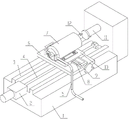
FIG. 1 is a perspective view of the structure of the present invention;
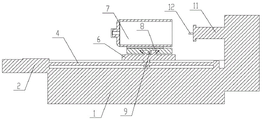
FIG. 2 is a front view of the present invention;
FIG. 3 is a view A-A of FIG. 2;
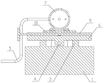
FIG. 4 is a view B-B of FIG. 3;
FIG. 5 is a view C-C of FIG. 3;
in the figure: 1-base, 2-servo motor, 3-guide rail, 4-screw, 5-cooling liquid injection pipe, 6-movable seat, 7-train brake cylinder, 8-slide rail, 9-screw, 10-workpiece support plate, 11-tool bit power mechanism and 12-tool bit.
Detailed Description
Referring to fig. 1-5, the embodiment is an inner wall processing device for a large-size train brake cylinder, and the inner wall processing device comprises a base 1, wherein two guide rails 3 are arranged at the top of the base 1 along the length direction, movable seats 6 moving along the guide rails 3 are arranged on the two guide rails 3, one end of the base 1 is provided with a driving mechanism a, the driving mechanism a is connected with the movable seats 6 to drive the movable seats 6 to move, slide rails 8 perpendicular to the guide rails 3 are arranged on the movable seats 6, a workpiece support plate 10 moving along the slide rails 8 is arranged on the slide rails 8, one side of each movable seat 6 is provided with a driving mechanism B, and the driving mechanism B is connected with the workpiece support plate 10 to drive the workpiece support plate 10 to move; a cutter head power mechanism 11 is arranged at the other end of the base 1, a cutter rest is arranged at the end part of an output shaft of the cutter head power mechanism 11, and a detachable cutter head 12 is arranged on the cutter rest; and a cooling liquid injection pipe 5 is arranged on one side of the base 1, a flange is arranged at the end part of the cooling liquid injection pipe 5, and the flange is used for being butted with an ear seat flange plate of a train brake cylinder 7.
This embodiment actuating mechanism A includes servo motor 2, and a screw rod 4 is equipped with to servo motor 2's output, and screw rod 4 is parallel with two guide rails 3, screw rod 4 with the threaded connection in movable seat 6 bottom.
In this embodiment, the driving mechanism B includes a screw rod 9, the screw rod 9 is in threaded connection with the bottom of the workpiece supporting plate 10, and a hand wheel is installed at the outer end of the screw rod 9.
In this embodiment, the slide rail 8 is composed of two rails symmetrically arranged in a dovetail shape, and the screw rod 9 is located between the two rails.
In this embodiment, the workpiece support plate 10 is provided with a plurality of mounting grooves, detachable locking bolts are installed in the mounting grooves, and the train brake cylinder 7 is fixed on the workpiece support plate 10 through the mounting grooves and the locking bolts.
Claims (5)
1. The inner wall machining device for the large-size train brake cylinder is characterized in that: the automatic cutting machine comprises a base, wherein two guide rails are arranged on the top of the base along the length direction, a movable seat moving along the guide rails is arranged on the two guide rails, a driving mechanism A is arranged at one end of the base and connected with the movable seat to drive the movable seat to move, a slide rail perpendicular to the guide rails is arranged on the movable seat, a workpiece supporting plate moving along the slide rail is arranged on the slide rail, a driving mechanism B is arranged on one side of the movable seat, and the driving mechanism B is connected with the workpiece supporting plate to drive the workpiece supporting plate to move; a cutter head power mechanism is arranged at the other end of the base, a cutter rest is arranged at the end part of an output shaft of the cutter head power mechanism, and a detachable cutter head is arranged on the cutter rest; and a cooling liquid injection pipe is arranged on one side of the base, a flange is arranged at the end part of the cooling liquid injection pipe, and the flange is used for being butted with an ear seat flange plate of the train brake cylinder.
2. The device for machining the inner wall of the large-size train brake cylinder as claimed in claim 1, wherein: the driving mechanism A comprises a servo motor, a screw rod is installed at the output end of the servo motor and is parallel to the two guide rails, and the screw rod is in threaded connection with the bottom of the movable seat.
3. The device for machining the inner wall of the large-size train brake cylinder as claimed in claim 1, wherein: the driving mechanism B comprises a screw rod, the screw rod is in threaded connection with the bottom of the workpiece supporting plate, and a hand wheel is mounted at the outer end of the screw rod.
4. The device for machining the inner wall of the large-size train brake cylinder as claimed in claim 3, wherein: the slide rail is composed of two rails which are symmetrically arranged in a dovetail shape, and the screw rod is positioned between the two rails.
5. The device for machining the inner wall of the large-size train brake cylinder as claimed in claim 1, wherein: the train brake cylinder is fixed on the workpiece supporting plate through the mounting groove and the locking bolts.
Priority Applications (1)
| Application Number | Priority Date | Filing Date | Title |
|---|---|---|---|
| CN202122617739.5U CN216359349U (en) | 2021-10-29 | 2021-10-29 | Inner wall machining device for large-size train brake cylinder |
Applications Claiming Priority (1)
| Application Number | Priority Date | Filing Date | Title |
|---|---|---|---|
| CN202122617739.5U CN216359349U (en) | 2021-10-29 | 2021-10-29 | Inner wall machining device for large-size train brake cylinder |
Publications (1)
| Publication Number | Publication Date |
|---|---|
| CN216359349U true CN216359349U (en) | 2022-04-22 |
Family
ID=81189940
Family Applications (1)
| Application Number | Title | Priority Date | Filing Date |
|---|---|---|---|
| CN202122617739.5U Active CN216359349U (en) | 2021-10-29 | 2021-10-29 | Inner wall machining device for large-size train brake cylinder |
Country Status (1)
| Country | Link |
|---|---|
| CN (1) | CN216359349U (en) |
-
2021
- 2021-10-29 CN CN202122617739.5U patent/CN216359349U/en active Active
Similar Documents
| Publication | Publication Date | Title |
|---|---|---|
| CN101961836B (en) | Numerically-controlled gantry type vertical and horizontal combined machine tool | |
| CN201792194U (en) | Numerical control gantry vertical-horizontal combined machine tool | |
| CN201960153U (en) | Special numerical control machine for drilling mortise lock cylinder shell | |
| CN102581664A (en) | Gear and rack type long shaft part multi-keyway milling fixture | |
| CN203343729U (en) | Numerically-controlled gantry vertical-and-horizontal compound machining center with tool magazines and main shafts compounded on saddles | |
| CN210548130U (en) | Axle type processing double-end lathe | |
| CN214979258U (en) | Multi-station special machine tool | |
| CN213794269U (en) | Tailstock assembly for machine tool | |
| CN216359349U (en) | Inner wall machining device for large-size train brake cylinder | |
| CN210099459U (en) | Milling and boring center hole and turning combined machine tool | |
| CN111761360A (en) | Large gantry vertical type numerical control boring and milling machine tool | |
| CN218193929U (en) | Turning, milling and grinding combined machining lathe | |
| CN215034177U (en) | Chamfering machine | |
| CN214770272U (en) | Special machine tool integrating drilling and chamfering | |
| CN211539550U (en) | Special boring device for headstock and box body of numerical control lathe | |
| CN202106436U (en) | Aluminium-wood tenon milling machine | |
| CN212761253U (en) | Steering gear shell processing device | |
| CN219901075U (en) | Rotary positioning mechanism of numerical control machine tool | |
| CN217166644U (en) | Planer type milling machine | |
| CN217966188U (en) | Numerical control broach front cutter grinding machine | |
| CN220427038U (en) | Multi-head chamfering machine equipment | |
| CN216542843U (en) | Adjustable stroke tooling clamp | |
| CN220717877U (en) | Tooling special for milling inner hole key groove | |
| CN220311987U (en) | Copper bar chamfering mechanism | |
| CN219617126U (en) | Milling and center hole drilling machine tool capable of automatically changing tool |
Legal Events
| Date | Code | Title | Description |
|---|---|---|---|
| GR01 | Patent grant | ||
| GR01 | Patent grant |