CN216102371U - Preceding sub vehicle frame structure and vehicle - Google Patents
Preceding sub vehicle frame structure and vehicle Download PDFInfo
- Publication number
- CN216102371U CN216102371U CN202121114111.7U CN202121114111U CN216102371U CN 216102371 U CN216102371 U CN 216102371U CN 202121114111 U CN202121114111 U CN 202121114111U CN 216102371 U CN216102371 U CN 216102371U
- Authority
- CN
- China
- Prior art keywords
- auxiliary frame
- plate
- upper plate
- front subframe
- front auxiliary
- Prior art date
- Legal status (The legal status is an assumption and is not a legal conclusion. Google has not performed a legal analysis and makes no representation as to the accuracy of the status listed.)
- Active
Links
Images


Abstract
The embodiment of the application provides a front auxiliary frame structure and a vehicle, and belongs to the technical field of automobiles, the front auxiliary frame structure comprises a front auxiliary frame upper plate and a front auxiliary frame lower plate, wherein the front auxiliary frame upper plate and the front auxiliary frame lower plate are mutually spliced; two groups of longitudinal supporting plates and at least two mutually independent transverse supporting plates connected between the two groups of longitudinal supporting plates are arranged between the front auxiliary frame upper plate and the front auxiliary frame lower plate; and two sides of each transverse supporting plate extend to the positions of the two groups of longitudinal supporting plates. Through the preceding sub vehicle frame structure and vehicle that this application embodiment provided, can improve the monomer mode of preceding sub vehicle frame.
Description
Technical Field
The embodiment of the application relates to the technical field of automobiles, in particular to a front auxiliary frame structure and a vehicle.
Background
The subframe can be regarded as a framework of the front axle and the rear axle, and is a component of the front axle and the rear axle. The front auxiliary frame of the automobile is directly connected with a transmission system, a power system, an exhaust system and an automobile body. If preceding sub vehicle frame structure is unreasonable, except that influence self mode, still can transmit exhaust system, driving system, the noise and the vibration on road surface to the automobile body, influence customer experience.
In addition, in the aspect of designing the front subframe, the NVH performance requirement is considered, and meanwhile, the low cost is ensured, so that in the design process of the front subframe, the performance and the cost are considered, the design technology content of the front subframe is very high, and the design platform concept of the automobile type of a company is more adapted.
The existing front auxiliary frame single body has low modal, and the dynamic stiffness of the front auxiliary frame and the chassis attachment point does not reach the standard.
SUMMERY OF THE UTILITY MODEL
The embodiment of the application provides a preceding sub vehicle frame structure and vehicle, aims at improving the monomer mode of preceding sub vehicle frame.
A first aspect of an embodiment of the present application provides a front subframe structure, including a front subframe upper plate and a front subframe lower plate, where the front subframe upper plate and the front subframe lower plate are spliced with each other;
two groups of longitudinal supporting plates and at least two mutually independent transverse supporting plates connected between the two groups of longitudinal supporting plates are arranged between the front auxiliary frame upper plate and the front auxiliary frame lower plate;
and two sides of each transverse supporting plate extend to the positions of the two groups of longitudinal supporting plates.
Optionally, the suspension system further comprises a suspension sleeve for mounting a suspension system of a vehicle, the suspension sleeve is connected with one of the transverse support plates, wherein the first transverse support plate connected with the suspension sleeve comprises two sub transverse support plates, and the two sub transverse support plates are respectively connected to two sides of the suspension sleeve.
Optionally, the transverse support plate is fixedly connected with the front subframe upper plate and the front subframe lower plate;
one side of at least one transverse supporting plate, which is abutted against the lower plate of the front auxiliary frame, is provided with a first connecting part, and the first connecting part is attached to the lower plate of the front auxiliary frame;
at least one on the horizontal backup pad with one side of preceding sub vehicle frame upper plate butt is provided with the second connecting portion, the second connecting portion with the laminating of preceding sub vehicle frame upper plate.
Optionally, a reinforcing part is arranged on each of the at least two transverse supporting plates.
Optionally, the steering gear frame further comprises steering gear mounting sleeves arranged between the front subframe upper plate and the front subframe lower plate, the steering gear mounting sleeves are positioned at two ends of one second transverse support plate in the length direction, and the steering gear mounting sleeves are connected with the second transverse support plates;
the longitudinal support plate is interconnected with the steering gear mounting sleeve.
Optionally, the vehicle body further comprises two arched pipes arranged between the front subframe upper plate and the front subframe lower plate, and the two groups of longitudinal supporting plates are respectively connected with the two arched pipes.
Optionally, a mounting hole is formed in the upper plate of the front subframe, and the position of the mounting hole corresponds to the position of the suspension sleeve.
A second aspect of embodiments of the present application provides a vehicle including a front subframe structure as provided in the first aspect of embodiments of the present application.
Has the advantages that:
the utility model provides a preceding sub vehicle frame structure and vehicle, through set up two sets of longitudinal support board in the front between sub vehicle frame upper plate and the preceding sub vehicle frame hypoplastron, be provided with two at least mutually independent horizontal backup pads again between two sets of longitudinal support boards, and make the both sides of horizontal backup pad extend to the position at two sets of longitudinal support board places, and like this, the space between preceding sub vehicle frame upper plate and the preceding sub vehicle frame hypoplastron has just formed three rows of cavity structures, thereby make the monomer mode of preceding sub vehicle frame effectively promote, the whole mode of vehicle automobile body and the dynamic stiffness of preceding sub vehicle frame and chassis mounting point have also been promoted simultaneously.
Drawings
In order to more clearly illustrate the technical solutions of the embodiments of the present application, the drawings needed to be used in the description of the embodiments of the present application will be briefly introduced below, and it is obvious that the drawings in the following description are only some embodiments of the present application, and it is obvious for those skilled in the art that other drawings can be obtained according to these drawings without inventive exercise.
FIG. 1 is a schematic structural view of an upper plate of a front subframe in the related art;
FIG. 2 is a schematic structural view of a lower plate and an inner portion of a front subframe in the related art;
FIG. 3 is a schematic structural view of a front subframe upper plate according to an embodiment of the present application;
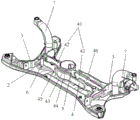
fig. 4 is a schematic structural diagram of a lower plate and an inner portion of a front subframe according to an embodiment of the present application.
Description of reference numerals: 1. a front subframe upper plate; 11. mounting holes; 2. a front subframe lower plate; 3. a longitudinal support plate; 4. a transverse support plate; 41. a first lateral support plate; 42. a sub-lateral support plate; 43. a second lateral support plate; 44. a first connection portion; 45. a second connecting portion; 46. a reinforcing portion; 5. a suspension sleeve; 6. a steering gear mounting sleeve; 7. an arched tube.
Detailed Description
The technical solutions in the embodiments of the present application will be clearly and completely described below with reference to the drawings in the embodiments of the present application, and it is obvious that the described embodiments are some, but not all, embodiments of the present application. All other embodiments, which can be derived by a person skilled in the art from the embodiments given herein without making any creative effort, shall fall within the protection scope of the present application.
In the related art, referring to fig. 1 and 2, a front subframe structure includes a front subframe upper plate 1 and a front subframe lower plate 2, two sets of longitudinal support plates 3 are disposed between the front subframe upper plate 1 and the front subframe lower plate 2, a transverse support plate 4 is disposed between the two sets of longitudinal support plates 3, and after the front subframe upper plate 1 and the front subframe lower plate 2 are attached, the longitudinal support plates 3 and the transverse support plates 4 form a support structure.
However, the single body mode of the front subframe structure in the related art is low, the dynamic stiffness of the attachment point of the front subframe and the chassis cannot meet the requirement, and the integral mode of the vehicle body can be affected even after the front subframe and the chassis are installed on a vehicle.
In view of this, the present application provides a front subframe structure and a vehicle, where two sets of longitudinal support plates are disposed between a front subframe upper plate and a front subframe lower plate, at least two mutually independent transverse support plates are disposed between the two sets of longitudinal support plates, and two sides of the transverse support plates extend to positions where the two sets of longitudinal support plates are located, so that a space between the front subframe upper plate and the front subframe lower plate forms a three-row cavity structure, thereby effectively improving a single mode of the front subframe, and simultaneously improving an overall mode of a vehicle body and dynamic stiffness of a front subframe and a chassis mounting point.
Example one
Referring to fig. 3 and 4, a front subframe structure disclosed in an embodiment of the present application includes a front subframe upper plate 1 and a front subframe lower plate 2, where the front subframe upper plate 1 and the front subframe lower plate 2 can be spliced together, and a receiving space is formed between the front subframe upper plate 1 and the front subframe lower plate 2; and set up corresponding spiro union point on preceding sub vehicle frame upper plate 1 and the preceding sub vehicle frame hypoplastron 2, can couple together preceding sub vehicle frame upper plate 1 and preceding sub vehicle frame hypoplastron 2 through the spiro union point.
Referring to fig. 4, two sets of longitudinal support plates 3 are disposed between a front subframe upper plate 1 and a front subframe lower plate 2, the longitudinal support plates 3 on both sides are respectively located on both sides of the front subframe lower plate 2, the longitudinal support plates 3 have the same length as the width of the front subframe lower plate 2 at the position, the upper side of the longitudinal support plates 3 is connected to the front subframe upper plate 1, and the lower side of the longitudinal support plates 3 is connected to the front subframe lower plate 2.
Referring to fig. 4, two lateral support plates 4 are further provided between the front subframe upper plate 1 and the front subframe lower plate 2, the two lateral support plates 4 are independent of each other, and specifically, the positions of the two lateral support plates 4 between the front subframe upper plate 1 and the front subframe lower plate 2 are separated. Two horizontal support plates 4 are located between two sets of longitudinal support plates 3, and both sides of each horizontal support plate 4 all extend to the position where two sets of longitudinal support plates 3 are located.
So after setting up, at first the length of vertical backup pad 3 has obtained the extension, make vertical backup pad 3 can support preceding sub vehicle frame upper plate 1 and preceding sub vehicle frame hypoplastron 2 better, secondly through two mutually independent horizontal backup pads 4, the cavity structure of three rows has been formed between preceding sub vehicle frame upper plate 1 and preceding sub vehicle frame hypoplastron 2, the accommodation space between the sub vehicle frame upper plate 1 and preceding sub vehicle frame hypoplastron 2 has just been separated into three mutually independent cavity before that, like this, the support intensity of preceding sub vehicle frame structure has just obtained effective promotion, thereby make the monomer mode of preceding sub vehicle frame structure effectively promote.
In other embodiments, more lateral support plates 4 may be provided, for example, three or more, but more lateral support plates 4 also means that the weight of the front subframe structure is heavier, and therefore, in order to ensure the light weight of the vehicle body, in practical applications, the number of lateral support plates 4 may be two to three.
In one embodiment, the front subframe structure needs to be connected to the suspension system of the vehicle. In order to better connect the suspension system to the front subframe structure, as shown in fig. 4, the front subframe structure further includes a suspension sleeve 5, the suspension sleeve 5 is located between the front subframe upper plate 1 and the front subframe lower plate 2, and the suspension sleeve 5 is connected to one of the lateral support plates 4, the lateral support plate 4 being a first lateral support plate 41.
Specifically, referring to fig. 4, the first lateral support plate 41 connected to the suspension sleeve 5 includes two sub lateral support plates 42, the two sub lateral support plates 42 are respectively connected to both sides of the suspension sleeve 5, and one side of the sub lateral support plate 42 is connected to the suspension sleeve 5 and the other side is connected to the longitudinal support plate 3.
So set up suspension sleeve 5 between preceding sub vehicle frame upper plate 1 and preceding sub vehicle frame hypoplastron 2, utilize suspension sleeve 5 can support preceding sub vehicle frame upper plate 1 and preceding sub vehicle frame hypoplastron 2 better to suspension sleeve 5 is connected with first horizontal backup pad 41, thereby has further strengthened the supporting effect of horizontal backup pad 4.
Meanwhile, referring to fig. 3, a mounting hole 11 is formed in the front subframe upper plate 1, and the position of the mounting hole 11 corresponds to the position of the suspension sleeve 5; after the front subframe upper plate 1 and the front subframe lower plate 2 are spliced, a part of the suspension sleeve 5 enters the mounting hole 11, and when the suspension system of the front subframe and the vehicle is connected, the suspension system is installed into the suspension sleeve 5 through the mounting hole 11.
In one embodiment, the lateral support plate 4 is fixedly connected to the front subframe upper plate 1 and the front subframe lower plate 2.
Specifically, referring to fig. 4, a first connecting portion 44 is disposed on the lateral support plate 4 and on a side of the lateral support plate 4 abutting against the front subframe lower plate 2, the first connecting portion 44 is attached to the front subframe lower plate 2 and is welded to the front subframe lower plate, the first connecting portion 44 extends along an edge of the lateral support plate 4, and the first connecting portion 44 and the lateral support plate 4 are integrally formed;
meanwhile, referring to fig. 4, a second connecting portion 45 is disposed on the lateral support plate 4 and on a side where the lateral support plate 4 abuts against the front subframe upper plate 1, the second connecting portion 45 is attached to and welded to the front subframe lower plate 2, the second connecting portion 45 extends along an edge of the lateral support plate 4, and the second connecting portion 45 and the lateral support plate 4 are integrally formed.
The contact area between the lateral support plate 4 and the front subframe upper plate 1 and the front subframe lower plate 2 can be increased by using the first connecting portion 44 and the second connecting portion 45, so that the connection effect between the lateral support plate 4 and the front subframe upper plate 1 and the front subframe lower plate 2 can be better.
It should be noted that in the present embodiment, one of the lateral support plates 4 may have the first connecting portion 44 and the second connecting portion 45, or each of the lateral support plates 4 may have the first connecting portion 44 and the second connecting portion 45.
In one embodiment, in order to improve the supporting strength of the lateral support plates 4, as shown in fig. 4, a reinforcing portion 46 is provided on each lateral support plate 4, and the reinforcing portion 46 is formed by protruding a portion of the lateral support plate 4 from the lateral support plate 4 by a stamping when the lateral support plate 4 is machined.
In one embodiment, referring to fig. 4, the front subframe structure further includes two steering gear mounting sleeves 6 disposed between the front subframe upper plate 1 and the front subframe lower plate 2, the two steering gear mounting sleeves 6 are respectively disposed at two ends of one of the second transverse support plates 43 in the length direction, where the second transverse support plate 4 refers to one transverse support plate 4 that is not connected to the suspension sleeve 5; and the second transverse supporting plate 43 and the steering gear mounting sleeve 6 are welded to each other.
The steering gear mounting sleeve 6 has a better supporting effect in the front subframe structure, so that the supporting strength of the transverse support plate 4 can be further improved by connecting one of the second transverse support plates 4 with the steering gear mounting sleeve 6.
Simultaneously two sets of longitudinal support plate 3 also respectively with two turn to quick-witted installation sleeve 6 one-to-one connection to improve longitudinal support plate 3's support intensity, and then improve the monomer mode of whole preceding sub vehicle frame structure.
In one embodiment, referring to fig. 4, the front subframe structure further comprises two arched tubes 7 arranged on the front subframe upper plate 1 and the front subframe lower plate 2, and two sets of longitudinal support plates 3 are welded and connected with the two arched tubes 7 in a one-to-one correspondence manner; the support strength of the longitudinal support plates 3 can be improved by the connection between the longitudinal support plates 3 and the arched tubes 7.
Example two
Based on the same inventive concept, the embodiment of the application discloses a vehicle, which comprises a front auxiliary frame structure provided by the embodiment of the application.
The overall mode of the vehicle body is effectively improved by improving the single mode of the front auxiliary frame structure.
It should be noted that, in the present specification, the embodiments are all described in a progressive manner, each embodiment focuses on differences from other embodiments, and the same and similar parts among the embodiments may be referred to each other.
It should also be noted that, in this document, the terms "center", "upper", "lower", "left", "right", "vertical", "horizontal", "inner", "outer", and the like indicate orientations or positional relationships based on the orientations or positional relationships shown in the drawings, and are only for convenience in describing the present invention and simplifying the description, but do not indicate or imply that the referred device or element must have a specific orientation, be constructed and operated in a specific orientation, and thus, should not be construed as limiting the present invention. Moreover, relational terms such as "first" and "second" are used solely to distinguish one entity or action from another entity or action without necessarily requiring or implying any actual such relationship or order between such entities or actions or should not be construed as indicating or implying relative importance. Also, the terms "comprises," "comprising," or any other variation thereof, are intended to cover a non-exclusive inclusion, such that a process, method, article, or terminal that comprises a list of elements does not include only those elements but may include other elements not expressly listed or inherent to such process, method, article, or terminal. Without further limitation, an element defined by the phrase "comprising an … …" does not exclude the presence of other identical elements in the process, method, article, or terminal equipment comprising the element.
The technical solutions provided by the present application are described in detail above, and the principles and embodiments of the present application are described herein by using specific examples, which are only used to help understanding the present application, and the content of the present description should not be construed as limiting the present application. While various modifications of the illustrative embodiments and applications will be apparent to those skilled in the art based upon this disclosure, it is not necessary or necessary to exhaustively enumerate all embodiments, and all obvious variations and modifications can be resorted to, falling within the scope of the disclosure.
Claims (8)
1. The utility model provides a preceding sub vehicle frame structure which characterized in that:
the auxiliary frame comprises a front auxiliary frame upper plate (1) and a front auxiliary frame lower plate (2), wherein the front auxiliary frame upper plate (1) and the front auxiliary frame lower plate (2) are spliced with each other;
two groups of longitudinal supporting plates (3) and at least two mutually independent transverse supporting plates (4) connected between the two groups of longitudinal supporting plates (3) are arranged between the front auxiliary frame upper plate (1) and the front auxiliary frame lower plate (2);
wherein both sides of each transverse support plate (4) extend to the positions of the two groups of longitudinal support plates (3).
2. The front subframe structure of claim 1 wherein:
the suspension sleeve (5) is used for installing a suspension system of a vehicle, the suspension sleeve (5) is connected with one of the transverse support plates (4), wherein a first transverse support plate (41) connected with the suspension sleeve (5) comprises two sections of sub transverse support plates (42), and the two sections of sub transverse support plates (42) are respectively connected to two sides of the suspension sleeve (5).
3. The front subframe structure of claim 1 wherein:
the transverse support plate (4) is fixedly connected with the front auxiliary frame upper plate (1) and the front auxiliary frame lower plate (2);
one side, abutted against the front subframe lower plate (2), of at least one transverse support plate (4) is provided with a first connecting part (44), and the first connecting part (44) is attached to the front subframe lower plate (2);
at least one on horizontal backup pad (4) with one side of preceding sub vehicle frame upper plate (1) butt is provided with second connecting portion (45), second connecting portion (45) with preceding sub vehicle frame upper plate (1) laminating.
4. The front subframe structure of claim 1 wherein:
and the at least two transverse supporting plates (4) are respectively provided with a reinforcing part (46).
5. The front subframe structure of claim 1 wherein:
the steering engine is characterized by further comprising steering engine mounting sleeves (6) arranged between the front auxiliary frame upper plate (1) and the front auxiliary frame lower plate (2), wherein the steering engine mounting sleeves (6) are located at two ends of one second transverse supporting plate (43) in the length direction, and the steering engine mounting sleeves (6) are connected with the second transverse supporting plates (43);
the longitudinal support plate (3) and the steering gear mounting sleeve (6) are connected to each other.
6. The front subframe structure of claim 1 wherein:
the automobile seat frame is characterized by further comprising two arched pipes (7) arranged between the front auxiliary frame upper plate (1) and the front auxiliary frame lower plate (2), and the two groups of longitudinal supporting plates (3) are respectively connected with the two arched pipes (7).
7. The front subframe structure of claim 2 wherein:
and a mounting hole (11) is formed in the upper plate (1) of the front auxiliary frame, and the position of the mounting hole (11) corresponds to the position of the suspension sleeve (5).
8. A vehicle, characterized in that: including a front sub frame structure according to any one of claims 1-7.
Priority Applications (1)
| Application Number | Priority Date | Filing Date | Title |
|---|---|---|---|
| CN202121114111.7U CN216102371U (en) | 2021-05-21 | 2021-05-21 | Preceding sub vehicle frame structure and vehicle |
Applications Claiming Priority (1)
| Application Number | Priority Date | Filing Date | Title |
|---|---|---|---|
| CN202121114111.7U CN216102371U (en) | 2021-05-21 | 2021-05-21 | Preceding sub vehicle frame structure and vehicle |
Publications (1)
| Publication Number | Publication Date |
|---|---|
| CN216102371U true CN216102371U (en) | 2022-03-22 |
Family
ID=80719914
Family Applications (1)
| Application Number | Title | Priority Date | Filing Date |
|---|---|---|---|
| CN202121114111.7U Active CN216102371U (en) | 2021-05-21 | 2021-05-21 | Preceding sub vehicle frame structure and vehicle |
Country Status (1)
| Country | Link |
|---|---|
| CN (1) | CN216102371U (en) |
-
2021
- 2021-05-21 CN CN202121114111.7U patent/CN216102371U/en active Active
Similar Documents
| Publication | Publication Date | Title |
|---|---|---|
| CN202783437U (en) | Blade electric vehicle floor board structure | |
| CN201193050Y (en) | Front auxiliary frame with adjustable installation dimension | |
| CN111791953A (en) | Integrally-formed lightweight cast beam assembly | |
| CN216102371U (en) | Preceding sub vehicle frame structure and vehicle | |
| CN105090338B (en) | Support used for assembling anti-vibration pad, vibration reduction assembly and air conditioning unit | |
| CN211107698U (en) | Rear auxiliary frame for extended-range automobile and automobile | |
| CN215285013U (en) | Regional additional strengthening of rear wheel casing and have its vehicle | |
| CN206012718U (en) | A kind of subframe mount structure | |
| CN212637074U (en) | Rear shock absorber mounting plate and rear shock absorber mounting assembly | |
| CN204587018U (en) | Rear secondary frame for vehicle | |
| CN202208317U (en) | Automobile frame | |
| CN209814099U (en) | Front auxiliary frame | |
| CN108482487B (en) | Novel tail beam structure for full-bearing passenger car underframe | |
| CN218929600U (en) | Car body rear end power transmission structure and car | |
| CN218751015U (en) | Automobile body bumper shock absorber biography force structure and vehicle | |
| JP3379373B2 (en) | Frame structure for ultra low floor bus | |
| CN218140929U (en) | Shock absorber supporting structure | |
| CN111497941A (en) | Auxiliary frame assembly and vehicle | |
| CN215244200U (en) | Fork arm connecting assembly for vehicle and vehicle | |
| CN203854730U (en) | Vehicle water tank cross beam | |
| CN215284973U (en) | Toe-in connecting rod mounting bracket, auxiliary frame and automobile | |
| CN212473651U (en) | Subframe and motor vehicle | |
| CN217918266U (en) | Connecting structure of damping device of balance car | |
| CN216332280U (en) | Sub vehicle frame linking bridge and vehicle thereof | |
| CN212766609U (en) | Main frame and motorcycle |
Legal Events
| Date | Code | Title | Description |
|---|---|---|---|
| GR01 | Patent grant | ||
| GR01 | Patent grant |