CN216004335U - Full-automatic pin inserting machine for relay chassis - Google Patents
Full-automatic pin inserting machine for relay chassis Download PDFInfo
- Publication number
- CN216004335U CN216004335U CN202121676760.6U CN202121676760U CN216004335U CN 216004335 U CN216004335 U CN 216004335U CN 202121676760 U CN202121676760 U CN 202121676760U CN 216004335 U CN216004335 U CN 216004335U
- Authority
- CN
- China
- Prior art keywords
- clamping
- shell
- pin
- seat
- pneumatic
- Prior art date
- Legal status (The legal status is an assumption and is not a legal conclusion. Google has not performed a legal analysis and makes no representation as to the accuracy of the status listed.)
- Active
Links
Images


Abstract
The utility model discloses a full-automatic pin inserting machine of a relay chassis, which comprises a rack, wherein a workbench is arranged on the rack, a controller with a touch screen for controlling the whole equipment to work is arranged on the workbench, a rotating disc is arranged on the workbench, and a shell feeding mechanism, a first detection mechanism, a first pin feeding mechanism, a second detection mechanism, a second pin feeding mechanism, a third detection mechanism, a pin bending mechanism and a blanking mechanism which are sequentially distributed by taking the rotating disc as the center are annularly arranged on the workbench; the shell positioning device comprises a rotating disc, a first driving motor, a fixed disc, more than one pneumatic locking clamp and a shell positioning mechanism, wherein more than one clamping station used for clamping a shell is arranged on the rotating disc, the first driving motor used for driving the rotating disc to rotate is arranged at the bottom of the rotating disc, the fixed disc is arranged above the rotating disc and is sleeved on an output shaft of the first driving motor, and more than one pneumatic locking clamp used for positioning the shell is also arranged on the fixed disc; this structure improves work efficiency.
Description
Technical Field
The utility model relates to the technical field of relay processing equipment, in particular to a full-automatic pin inserting machine for a relay chassis.
Background
The relay is a widely used electronic component, and it is applied to fields such as domestic appliance, car, industrial control, electric power system, communication device, and the relay generally contains the chassis, and the chassis generally contains casing and two contact pins, inserts the contact pin in the casing, then bends the contact pin, but adds to the relay chassis and adds and to have following several problems: 1. the whole volume of the equipment is huge due to the current assembly line processing of equipment products; 2. the equipment structure is relatively complex and the operation is inconvenient; 3. a plurality of detection stations are mainly added in the production line machining process, and generally manual detection is needed at present, so that the detection efficiency is low, and the improvement is needed.
Disclosure of Invention
The utility model aims to provide a full-automatic pin inserting machine of a relay chassis, which aims to solve the problems of low working efficiency, large integral volume, complex structure and inconvenient operation in the background technology.
In order to achieve the purpose, the utility model provides the following technical scheme: the utility model provides a machine is participated in full-automatic on relay chassis, includes the frame, is provided with the workstation in the frame, is provided with the controller of taking the touch-sensitive screen of the whole equipment work of control on the workstation, is provided with the rotary disk on the workstation, and the annular is provided with on the workstation and uses the rotary disk as the center and carry out the following equipment that distributes according to the order in proper order:
the shell feeding mechanism is used for feeding the shell;
the first detection mechanism is used for detecting whether the shell is placed or not;
a first pin feeding mechanism for inserting one of the pins into the housing;
the second detection mechanism is used for detecting whether the contact pin is inserted into the shell or not;
the second pin feeding mechanism is used for inserting the other pin into the shell;
a third detection mechanism for detecting whether the contact pin is inserted into the shell;
the contact pin bending mechanism is used for bending the two contact pins;
the blanking mechanism is used for conveying qualified products to the qualified conveying channel and conveying unqualified products to the unqualified conveying channel;
the clamping mechanism comprises a rotating disk, a first driving motor, a fixed disk, a pneumatic locking clamp and a second driving motor, wherein more than one clamping stations used for clamping a shell are arranged on the rotating disk, the first driving motor driving the rotating disk to rotate is arranged at the bottom of the rotating disk, the fixed disk is arranged above the rotating disk and sleeved on an output shaft of the first driving motor, the fixed disk is fixedly arranged when the output shaft of the first driving motor rotates, and more than one pneumatic locking clamp used for positioning the shell is further arranged on the fixed disk.
In order to clamp the shell, the clamping station comprises a clamping seat, a clamping opening for placing the shell is formed in the clamping seat, and pneumatic chucks capable of changing the size of the clamping opening are connected to the two sides of the clamping opening in a sliding mode.
Preferably, the first detection mechanism, the second detection mechanism and the third detection mechanism each comprise a detection support, a first cylinder is arranged on the detection support, and a piston rod of the first cylinder is connected with a detection camera for detection.
In order to facilitate blanking, the blanking mechanism comprises a first clamping component for conveying unqualified products and a second clamping component for conveying qualified products, the first clamping component and the second clamping component have the same structure and respectively comprise a clamping seat, a first horizontal bracket is arranged on the clamping seat, a first sliding rail is arranged on the first horizontal bracket, a first fixed seat which is vertically arranged is connected on the first sliding rail in a sliding way, a second air cylinder which is vertically arranged is arranged above the first fixed seat, a second sliding rail is arranged on the first fixed seat, a piston rod of the second air cylinder is connected with a first pneumatic clamp, the first pneumatic clamp is connected on the second sliding rail in a sliding way, a third air cylinder for driving the first fixed seat to slide on the first sliding rail is arranged at the side edge of the first horizontal bracket, and an unqualified conveying channel is arranged at the side edge of the first clamping component, and a qualified conveying channel is arranged on the side edge of the second clamping assembly.
In order to facilitate feeding, the shell feeding mechanism comprises a feeding seat, a shell conveying channel and a clamping unit are arranged on the feeding seat, the clamping unit comprises a clamping seat, a second horizontal support is arranged above the clamping seat, a third sliding rail is arranged on the second horizontal support, a second fixed seat is connected to the third sliding rail in a sliding manner, four fourth air cylinders are arranged above the second fixed seat at intervals, four fourth sliding rails are arranged on the second fixed seat, a piston rod of each fourth air cylinder is connected with a second pneumatic clamp, the second pneumatic clamp is connected to the fourth sliding rail in a sliding manner, a rotating mechanism for rotationally positioning the shell is arranged below the clamping seat, a temporary storage table is arranged on one side of the rotating mechanism, the shell conveying channel is arranged on the other side of the rotating mechanism, and the second pneumatic clamp on the left side clamps the shell on the conveying channel and sends the shell into the rotating mechanism, the second pneumatic fixture on the right side sends the shell on the temporary storage table to the clamping station, a fifth cylinder for driving the second fixing seat to slide on the third sliding rail is arranged on the side edge of the second horizontal support, and a positioning detection mechanism located above the rotating mechanism is further arranged on the material clamping seat.
In order to facilitate operation, the second contact pin feeding mechanism and the first contact pin feeding mechanism are consistent in structure and respectively comprise a contact pin conveying mechanism and a contact pin mechanism, the contact pin conveying mechanism comprises a contact pin base, a vibration conveying channel used for conveying contact pins is arranged on the contact pin base, a right-angle rotating mechanism used for horizontally placing the contact pins in rotation degree is arranged on the other side of the vibration conveying channel, the contact pin mechanism comprises a pneumatic sliding rail, a vertical frame is arranged on the pneumatic sliding rail, a sixth air cylinder is arranged above the vertical frame, the output of the sixth air cylinder is connected with an insertion rod used for inserting the contact pins on the rotated right-angle rotating mechanism into a shell, a guide seat used for guiding the insertion rod is arranged at the front end of the vertical frame, and a first guide rod matched with the pneumatic sliding rail is arranged above a fixed disc.
Compared with the prior art, the utility model has the following beneficial effects: above-mentioned structure sets up, utilizes the rotary disk to carry out the rotary conveying for whole volume diminishes, easy operation moreover, and adopts automated inspection in the whole process, improves work efficiency, reduces the cost of labor.
Drawings
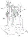
Fig. 1 is a schematic overall structure diagram of a fully automatic pin inserting machine of a relay chassis in embodiment 1;
FIG. 2 is a plan view showing a structure of a fully automatic pin-on-machine controller of a relay chassis according to embodiment 1;
FIG. 3 is a schematic structural view of a holding station in embodiment 1;
FIG. 4 is a schematic view showing the structure of one of the detecting units in embodiment 1;
FIG. 5 is a schematic structural view of a first clamping assembly in accordance with embodiment 1;
fig. 6 is a first schematic structural diagram of the case feeding mechanism in embodiment 1 when the second pneumatic clamp on the right side is not provided with a third slide rail and a cylinder block;
FIG. 7 is a second schematic structural view of the feeding mechanism of the case in embodiment 1;
FIG. 8 is a schematic structural view of the pin transport mechanism in embodiment 1 when the right-angle rotary mechanism is connected to the vibrating transport channel;
FIG. 9 is a schematic structural view of a needle inserting mechanism according to embodiment 1;
FIG. 10 is a schematic structural view of the insertion needle transport mechanism at 90 degrees selected by the right angle rotation mechanism in embodiment 1;
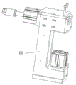
fig. 11 is a schematic structural view of the pin bending mechanism in embodiment 1.
In the figure: the device comprises a rack 1, a workbench 2, a controller 3, a rotating disc 4, a shell feeding mechanism 5, a first detection mechanism 6, a first pin feeding mechanism 7, a second detection mechanism 8, a second pin feeding mechanism 9, a third detection mechanism 10, a pin bending mechanism 11, a blanking mechanism 12, a clamping station 13, a first driving motor 14, a fixed disc 15, a pneumatic locking clamp 16, a clamping seat 17, a clamping opening 18, a pneumatic clamping head 19, a detection support 20, a first cylinder 21, a detection camera 22, a first clamping component 23, a second clamping component 24, a clamping seat 25, a first horizontal support 26, a first sliding rail 27, a first fixed seat 28, a second cylinder 29, a second sliding rail 30, a first pneumatic clamp 31, a third cylinder 32, an unqualified conveying channel 33, a qualified conveying channel 34, a feeding seat 35, a shell conveying channel 36, a clamping unit 37, a clamping seat 38, a second horizontal support 39, a shell conveying channel 36, a clamping unit 37, a qualified conveying channel 33, a detection device and a detection device, The device comprises a third slide rail 40, a second fixed seat 41, a fourth air cylinder 42, a fourth slide rail 44, a second pneumatic fixture 43, a rotating mechanism 45, a temporary storage table 46, a fifth air cylinder 47, a positioning detection mechanism 48, a pin conveying mechanism 49, a pin mechanism 50, a pin base 51, a vibration conveying channel 52, a right-angle rotating mechanism 53, a pneumatic slide rail 54, a vertical frame 55, a sixth air cylinder 56, an inserting rod 57, a guide base 58, a first guide rod 59, a clamping groove 53-1, a shell 60, a seventh air cylinder 61, a pressing plate 62 and an air cylinder base 63.
Detailed Description
The technical solutions in the embodiments of the present invention will be clearly and completely described below with reference to the drawings in the embodiments of the present invention, and it is obvious that the described embodiments are only a part of the embodiments of the present invention, and not all of the embodiments. All other embodiments, which can be derived by a person skilled in the art from the embodiments given herein without making any creative effort, shall fall within the protection scope of the present invention.
In the description of the present invention, it should be noted that the terms "upper", "lower", "inner", "outer", "front", "rear", "both ends", "one end", "the other end", and the like indicate orientations or positional relationships based on those shown in the drawings, and are only for convenience of description and simplicity of description, but do not indicate or imply that the referred device or element must have a specific orientation, be constructed in a specific orientation, and be operated, and thus, should not be construed as limiting the present invention. Furthermore, the terms "first" and "second" are used for descriptive purposes only and are not to be construed as indicating or implying relative importance.
In the description of the present invention, it is to be noted that, unless otherwise explicitly specified or limited, the terms "mounted," "disposed," "connected," and the like are to be construed broadly, such as "connected," which may be fixedly connected, detachably connected, or integrally connected; can be mechanically or electrically connected; they may be connected directly or indirectly through intervening media, or they may be interconnected between two elements. The specific meanings of the above terms in the present invention can be understood in specific cases to those skilled in the art.
Example 1:
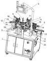
referring to fig. 1-11, an embodiment of the present invention is shown: the utility model provides a full-automatic machine of participating in on relay chassis, includes frame 1, is provided with workstation 2 in frame 1, is provided with the controller 3 of taking the touch-sensitive screen of the whole equipment work of control on workstation 2, is provided with rotary disk 4 on workstation 2, and the ring shape is provided with on workstation 2 and uses rotary disk 4 as the center and carry out the following equipment that distributes according to the order in proper order:
a shell feeding mechanism 5 for feeding the shell;
a first detecting mechanism 6 for detecting whether the housing is placed;
a first pin feeding mechanism 7 for inserting one of the pins into the housing;
a second detecting mechanism 8 for detecting whether the pin is inserted into the housing;
a second pin feeding mechanism 9 for inserting another pin into the housing;
a third detecting mechanism 10 for detecting whether the pin is inserted into the housing;
a pin bending mechanism 11 for bending the two pins;
the blanking mechanism 12 is used for conveying qualified products to the qualified conveying channel 34 and conveying unqualified products to the unqualified conveying channel 33;
the clamping device comprises a rotating disk 4, a first driving motor 14, a fixed disk 15, a pneumatic locking clamp 16 and a second driving motor 15, wherein more than one clamping stations 13 used for clamping a shell are arranged on the rotating disk 4, the first driving motor 14 driving the rotating disk 4 to rotate is arranged at the bottom of the rotating disk 4, the fixed disk 15 is arranged above the rotating disk 4 in a sleeved mode and is connected to an output shaft of the first driving motor 14 in a sleeved mode, when the output shaft of the first driving motor 14 rotates, the fixed disk 15 is fixedly arranged, and more than one pneumatic locking clamp 16 used for positioning the shell is further arranged on the fixed disk 15.
When the structure is arranged to work, firstly, the shell is fed by the shell feeding mechanism 5 and is put on the rotating disc 4 through the shell, then the feeding station is rotated to the station of the first pin feeding mechanism 7 in the rotating process of the rotating disc 4 to detect the clamping station 13 at the moment, whether the shell 60 is placed or not is detected, then the shell is conveyed to the first pin feeding mechanism 7, the shell 60 on the station corresponding to the first pin feeding mechanism 7 at the moment is clamped by the pneumatic locking clamp 16, then a pin is installed by the first pin feeding mechanism 7, then the shell is moved to the position of the second detecting mechanism 8 under the rotating action of the rotating disc 4 to detect whether the pin is placed or not, the shell is moved to the second pin feeding mechanism 9 under the rotating action of the rotating disc 4, the shell 60 on the station corresponding to the second pin feeding mechanism 9 at the moment is clamped by the pneumatic locking clamp 16, then utilize second contact pin feed mechanism 9, another contact pin of installation, then under the rotatory effect of rotary disk 4, move to third detection mechanism 10 position, whether the contact pin has been placed in the detection, then move contact pin bending mechanism 11 and bend the processing to two contact pins, then according to the data message that the place ahead detected, and separately carry qualified product and nonconforming product through unloading mechanism 12, through the above-mentioned structural setting, utilize rotary disk 4 to carry out the rotary transportation, make whole volume diminish, moreover, the operation is simple, and adopt automated inspection in the whole process, and the work efficiency is improved, and the labor cost is reduced.
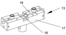
In order to clamp the shell, the clamping station 13 comprises a clamping seat 17, a clamping opening 18 for placing the shell is formed in the clamping seat 17, pneumatic clamping heads 19 capable of changing the size of the clamping opening 18 are connected to the two sides of the clamping opening 18 in a sliding mode, and the shell can be effectively clamped through the structural arrangement.
Preferably, the first detection mechanism 6, the second detection mechanism 8 and the third detection mechanism 10 each include a detection bracket 20, a first cylinder 21 is disposed on the detection bracket 20, and a detection camera 22 for detection is connected to a piston rod of the first cylinder 21.
In order to facilitate blanking, the blanking mechanism 12 includes a first clamping assembly 23 for conveying unqualified products and a second clamping assembly 24 for conveying qualified products, the first clamping assembly 23 and the second clamping assembly 24 are located at two sides of the pin bending mechanism 11, the first clamping assembly 23 and the second clamping assembly 24 have the same structure, and both include a clamping base 25, a first horizontal bracket 26 is arranged on the clamping base 25, a first slide rail 27 is arranged on the first horizontal bracket 26, a vertically arranged first fixing base 28 is slidably connected on the first slide rail 27, a vertically arranged second air cylinder 29 is arranged above the first fixing base 28, a second slide rail 30 is arranged on the first fixing base 28, a piston rod of the second air cylinder 29 is connected with a first pneumatic clamp 31, the first pneumatic clamp 31 is slidably connected on the second slide rail 30, the side of the first horizontal support 26 is provided with a third cylinder 32 for driving the first fixing seat 28 to slide on the first slide rail 27, the side of the first clamping assembly 23 is provided with an unqualified conveying channel 33, the side of the second clamping assembly 24 is provided with a qualified conveying channel 34, qualified products are clamped and placed on the unqualified conveying channel 33 by the first clamping assembly 23 through the upper structure conveying, and the qualified products are placed on the qualified conveying channel 34 by the second clamping assembly 24.
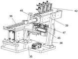
In order to facilitate loading, the shell loading mechanism 5 includes a loading seat 35, a shell conveying channel 36 and a clamping unit 37 are arranged on the loading seat 35, the clamping unit 37 includes a clamping seat 38, a second horizontal bracket 39 is arranged above the clamping seat 38, a third slide rail 40 is arranged on the second horizontal bracket 39, a second fixed seat 41 is connected on the third slide rail 40 in a sliding manner, four fourth air cylinders 42 are arranged above the second fixed seat 41 at intervals, each fourth air cylinder 42 is arranged on the second fixed seat 41 through an air cylinder seat 63, four fourth slide rails 44 are arranged on the second fixed seat 41, a piston rod of each fourth air cylinder 42 is connected with a second pneumatic clamp 43, the second pneumatic clamp 43 is connected on the fourth slide rail 44 in a sliding manner, a rotating mechanism 45 for rotationally positioning the shell is arranged below the clamping seat 38, a temporary storage table 46 is arranged on one side of the rotating mechanism 45, the shell conveying channel 36 is arranged on the other side of the rotating mechanism 45, the shell on the conveying channel 36 is clamped and conveyed to the rotating mechanism 45 by the second pneumatic clamp 43 on the left side, the shell on the temporary storage table 46 is conveyed to the clamping station 13 by the second pneumatic clamp 43 on the right side, a fifth air cylinder 47 for driving the second fixed seat 41 to slide on the third slide rail 40 is arranged on the side edge of the second horizontal support 39, a positioning detection mechanism 48 positioned above the rotating mechanism 45 is also arranged on the clamping seat 38, when the clamping device works, the shells 60 are sequentially conveyed by the shell conveying channel 36, then the corresponding shells are clamped by the 4 second pneumatic clamps 43, when the fifth air cylinder 47 works, the second fixed seat 41 can be pushed to slide along the third slide rail 40, then the fourth air cylinder 42 is driven to drive the corresponding second pneumatic clamp 43 to move up and down, to clamp the corresponding shell 60, the second pneumatic clamp 43 on the left side is used for clamping the shell on the shell conveying channel 36 and putting the shell into the rotating mechanism 45, then the positioning detection mechanism 48 is used for detecting whether the shell on the rotating mechanism 45 is in a proper position, if the shell is not swung as required, the rotating mechanism 45 is driven to rotate,
the shell is placed right, then the third second pneumatic clamp 43 is used for clamping the shell on the rotating mechanism 45 and is placed into the temporary storage table 46, the second pneumatic clamp 43 on the right side is used for clamping the shell on the temporary storage table 46 and is placed into the clamping station 13, therefore, the shells on different stations can be clamped at one time and placed on corresponding operation stations through the structure, and the overall working efficiency is further improved.
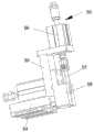
For convenience of operation, the second pin feeding mechanism 9 and the first pin feeding mechanism 7 have the same structure, and each of the second pin feeding mechanism and the first pin feeding mechanism includes a pin conveying mechanism 49 and a pin mechanism 50, the pin conveying mechanism 49 includes a pin base 51, a vibration conveying channel 52 for conveying pins is provided on the pin base 51, a right-angle rotating mechanism 53 for rotating the horizontally placed pins by 90 degrees is provided on the other side of the vibration conveying channel 52, the pin mechanism 50 includes a pneumatic slide rail 54, a vertical frame 55 is provided on the pneumatic slide rail 54, a sixth air cylinder 56 is provided above the vertical frame 55, the sixth air cylinder 56 is output and connected with an inserting rod 57 for inserting the pins on the rotated right-angle rotating mechanism 53 into the housing, a guide base 58 for guiding the inserting rod 57 is provided at the front end of the vertical frame 55, a first guide rod 59 matched with the pneumatic slide rail 54 is provided above the fixed disk 15, through the structural arrangement, when a certain station in the rotating process of the rotating disc 4 reaches the corresponding second pin feeding mechanism 9 and first pin feeding mechanism 7, at this time, pins are firstly conveyed by the vibration conveying channel 52, then the pins are conveyed to the other end of the vibration conveying channel 52, and are clamped into the clamping groove 53-1 of the right-angle rotating mechanism 53 during continuous conveying, then the pins are rotated by 90 degrees by the right-angle rotating mechanism 53, and are changed from the original horizontal placement into the vertical placement, the vertical pins are just ensured to be positioned right above the jacks corresponding to the shell, at this time, the pneumatic slide rail 54 is driven to work, the inserting rod 57 is moved right above the pins, then the sixth air cylinder 56 is driven to work, the inserting rod 57 is moved downwards along the guide seat 58, finally the vertical pins are inserted into the jacks corresponding to the shell, the installation effect on the pins is realized, and the whole structure realizes automatic operation, in order to ensure the accuracy, an inductive sensor electrically connected to the controller 3 is disposed at a corresponding position to achieve the positioning accuracy, and the specific position and operation principle of the inductive sensor are conventional in the art and therefore are not described in detail.
The pin seat 51 is also provided with a driving mechanism for sending the pins on the vibration conveying channel 52 into the slots 53-1 of the right-angle rotating mechanism 53, the driving mechanism comprises a seventh air cylinder 61 and a pressing plate 62 connected with the output of the seventh air cylinder, and the pins on the vibration conveying channel 52 are pressed into the slots 53-1 of the right-angle rotating mechanism 53 when the pressing plate 62 moves downwards.
The applicant should note that the pneumatic locking clamp 16, the rotating mechanism 45, the positioning detection mechanism 48, the right-angle rotating mechanism 53 and the pin bending mechanism 11 are all conventional technologies, and therefore, the details thereof are not described in detail.
It will be evident to those skilled in the art that the utility model is not limited to the details of the foregoing illustrative embodiments, and that the present invention may be embodied in other specific forms without departing from the spirit or essential attributes thereof. The present embodiments are therefore to be considered in all respects as illustrative and not restrictive, the scope of the utility model being indicated by the appended claims rather than by the foregoing description, and all changes which come within the meaning and range of equivalency of the claims are therefore intended to be embraced therein. Any reference sign in a claim should not be construed as limiting the claim concerned.
Claims (6)
1. The utility model provides a full-automatic machine of participating in on relay chassis, includes frame (1), is provided with workstation (2) in frame (1), is provided with controller (3) of taking the touch-sensitive screen of the whole equipment work of control on workstation (2), its characterized in that: the rotary table (2) is provided with a rotary disc (4), and the rotary table (2) is annularly provided with the following devices which are distributed by taking the rotary disc (4) as the center in sequence:
a shell feeding mechanism (5) for feeding the shell;
a first detection mechanism (6) for detecting whether the housing is placed;
a first pin feeding mechanism (7) for inserting one of the pins into the housing;
a second detection mechanism (8) for detecting whether the pin is inserted into the housing;
a second pin feeding mechanism (9) for inserting another pin into the housing;
a third detecting mechanism (10) for detecting whether the pin is inserted into the housing;
a pin bending mechanism (11) for bending the two pins;
a blanking mechanism (12) for conveying qualified products to a qualified conveying channel (34) and conveying unqualified products to an unqualified conveying channel (33);
the clamping device comprises a rotating disk (4), more than one clamping station (13) used for clamping a shell is arranged on the rotating disk (4), a first driving motor (14) used for driving the rotating disk (4) to rotate is arranged at the bottom of the rotating disk (4), a fixed disk (15) is arranged above the rotating disk (4), the fixed disk (15) is sleeved on an output shaft of the first driving motor (14), when the output shaft of the first driving motor (14) rotates, the fixed disk (15) is fixedly arranged, and more than one pneumatic locking clamp (16) used for positioning the shell is further arranged on the fixed disk (15).
2. The full-automatic pin machine of the relay chassis according to claim 1, characterized in that: the clamping station (13) comprises a clamping seat (17), a clamping opening (18) for placing the shell is formed in the clamping seat (17), and pneumatic chucks (19) capable of changing the size of the clamping opening (18) are connected to the two sides of the clamping opening (18) in a sliding mode.
3. The full-automatic pin machine of the relay chassis according to claim 1, characterized in that: the first detection mechanism (6), the second detection mechanism (8) and the third detection mechanism (10) comprise detection supports (20), first air cylinders (21) are arranged on the detection supports (20), and detection cameras (22) used for detection are connected to piston rods of the first air cylinders (21).
4. The full-automatic pin machine of the relay chassis according to claim 1, characterized in that: the blanking mechanism (12) comprises a first clamping component (23) used for conveying unqualified products and a second clamping component (24) used for conveying qualified products, the first clamping component (23) and the second clamping component (24) have the same structure and respectively comprise a clamping seat (25), a first horizontal support (26) is arranged on the clamping seat (25), a first sliding rail (27) is arranged on the first horizontal support (26), a first fixing seat (28) which is vertically arranged is connected on the first sliding rail (27) in a sliding manner, a second air cylinder (29) which is vertically arranged is arranged above the first fixing seat (28), a second sliding rail (30) is arranged on the first fixing seat (28), a piston rod of the second air cylinder (29) is connected with a first pneumatic clamp (31), and the first pneumatic clamp (31) is connected on the second sliding rail (30) in a sliding manner, and a third air cylinder (32) for driving the first fixing seat (28) to slide on the first sliding rail (27) is arranged at the side edge of the first horizontal support (26), an unqualified conveying channel (33) is arranged at the side edge of the first clamping assembly (23), and a qualified conveying channel (34) is arranged at the side edge of the second clamping assembly (24).
5. The full-automatic pin machine of the relay chassis according to claim 1, characterized in that: the shell feeding mechanism (5) comprises a feeding seat (35), a shell conveying channel (36) and a clamping unit (37) are arranged on the feeding seat (35), the clamping unit (37) comprises a clamping seat (38), a second horizontal support (39) is arranged above the clamping seat (38), a third sliding rail (40) is arranged on the second horizontal support (39), a second fixed seat (41) is connected on the third sliding rail (40) in a sliding manner, four fourth air cylinders (42) are arranged above the second fixed seat (41) at intervals, four fourth sliding rails (44) are arranged on the second fixed seat (41), a piston rod of each fourth air cylinder (42) is connected with a second pneumatic clamp (43), the second pneumatic clamp (43) is connected on the fourth sliding rails (44) in a sliding manner, a rotating mechanism (45) for rotationally positioning the shell is arranged below the clamping seat (38), one side of the rotating mechanism (45) is provided with a temporary storage table (46), the other side of the rotating mechanism (45) is provided with a shell conveying channel (36), a second pneumatic clamp (43) on the left side clamps a shell on the conveying channel (36) and sends the shell into the rotating mechanism (45), a second pneumatic clamp (43) on the right side sends the shell on the temporary storage table (46) into the clamping station (13), a fifth cylinder (47) for driving a second fixed seat (41) to slide on a third sliding rail (40) is arranged on the side edge of a second horizontal support (39), and a positioning detection mechanism (48) located above the rotating mechanism (45) is further arranged on the clamping seat (38).
6. The full-automatic pin machine of the relay chassis according to claim 1, characterized in that: the second pin feeding mechanism (9) and the first pin feeding mechanism (7) are consistent in structure and respectively comprise a pin conveying mechanism (49) and a pin mechanism (50), the pin conveying mechanism (49) comprises a pin base (51), a vibration conveying channel (52) for conveying pins is arranged on the pin base (51), a right-angle rotating mechanism (53) for rotating the pins horizontally placed by 90 degrees is arranged on the other side of the vibration conveying channel (52), the pin mechanism (50) comprises a pneumatic sliding rail (54), a vertical frame (55) is arranged on the pneumatic sliding rail (54), a sixth air cylinder (56) is arranged above the vertical frame (55), the sixth air cylinder (56) is in output connection with an inserting rod (57) for inserting the pins on the rotated right-angle rotating mechanism (53) into the shell, a guide base (58) for guiding the inserting rod (57) is arranged at the front end of the vertical frame (55), a first guide rod (59) matched with the pneumatic slide rail (54) is arranged above the fixed disc (15).
Priority Applications (1)
| Application Number | Priority Date | Filing Date | Title |
|---|---|---|---|
| CN202121676760.6U CN216004335U (en) | 2021-07-22 | 2021-07-22 | Full-automatic pin inserting machine for relay chassis |
Applications Claiming Priority (1)
| Application Number | Priority Date | Filing Date | Title |
|---|---|---|---|
| CN202121676760.6U CN216004335U (en) | 2021-07-22 | 2021-07-22 | Full-automatic pin inserting machine for relay chassis |
Publications (1)
| Publication Number | Publication Date |
|---|---|
| CN216004335U true CN216004335U (en) | 2022-03-11 |
Family
ID=80589030
Family Applications (1)
| Application Number | Title | Priority Date | Filing Date |
|---|---|---|---|
| CN202121676760.6U Active CN216004335U (en) | 2021-07-22 | 2021-07-22 | Full-automatic pin inserting machine for relay chassis |
Country Status (1)
| Country | Link |
|---|---|
| CN (1) | CN216004335U (en) |
Cited By (1)
| Publication number | Priority date | Publication date | Assignee | Title |
|---|---|---|---|---|
| CN116540088A (en) * | 2023-06-26 | 2023-08-04 | 深圳市优界科技有限公司 | Automatic detection device for relay |
-
2021
- 2021-07-22 CN CN202121676760.6U patent/CN216004335U/en active Active
Cited By (2)
| Publication number | Priority date | Publication date | Assignee | Title |
|---|---|---|---|---|
| CN116540088A (en) * | 2023-06-26 | 2023-08-04 | 深圳市优界科技有限公司 | Automatic detection device for relay |
| CN116540088B (en) * | 2023-06-26 | 2023-09-12 | 深圳市优界科技有限公司 | Automatic detection device for relay |
Similar Documents
| Publication | Publication Date | Title |
|---|---|---|
| CN103862838B (en) | A kind of full-automatic consent, two-sided, silk-screen all-in-one | |
| CN202137569U (en) | Pin plugging machine for radiators | |
| CN206422364U (en) | A kind of fully automatic feeding device of automotive wire bundle inserting terminal press-connection machine | |
| CN109866019B (en) | Mobile phone wireless earphone charging box assembling equipment and operation method thereof | |
| CN216004335U (en) | Full-automatic pin inserting machine for relay chassis | |
| CN206263143U (en) | A kind of electronic component pin forming machine | |
| CN208543108U (en) | A kind of high-accuracy fixture for laser welding of flexibility | |
| CN206422370U (en) | A kind of step-by-step movement loading plate of terminal crimping connector automatic charging device | |
| CN216462833U (en) | Metal plug connector positioning and feeding device | |
| CN115008180B (en) | Automatic assembly equipment | |
| CN115400960B (en) | Shaping test braid equipment of metal tantalum capacitor | |
| CN217424347U (en) | Detection apparatus for electric core outward appearance | |
| CN110449883A (en) | A kind of positioning charging apparatus of fiber cabling terminal | |
| CN216271506U (en) | Automatic feeding device for machining waterproof vent valve | |
| CN214123933U (en) | Electricity core processing equipment | |
| CN211830509U (en) | Automatic pressure equipment machine of motor stator with material loading ware | |
| CN108704862A (en) | Dynamic lithium battery PACK line battery core intelligence sorting machines | |
| CN209766563U (en) | automatic processing equipment for battery cell | |
| CN111799628A (en) | Automatic jacketing machine for carbon brush | |
| CN208774080U (en) | A kind of power supply ultrasonic bonding material conveying device | |
| CN217237714U (en) | Put device and transformer skeleton automated inspection equipment | |
| CN218601400U (en) | Fill electric pile automatic test equipment | |
| CN216829044U (en) | Circuit board welding device with high stability and quick cooling function | |
| CN215575442U (en) | Motor detection device | |
| CN220347697U (en) | Automatic assembling device for electric drill chuck |
Legal Events
| Date | Code | Title | Description |
|---|---|---|---|
| GR01 | Patent grant | ||
| GR01 | Patent grant |