CN215946554U - Pipe elevator - Google Patents
Pipe elevator Download PDFInfo
- Publication number
- CN215946554U CN215946554U CN202122387569.6U CN202122387569U CN215946554U CN 215946554 U CN215946554 U CN 215946554U CN 202122387569 U CN202122387569 U CN 202122387569U CN 215946554 U CN215946554 U CN 215946554U
- Authority
- CN
- China
- Prior art keywords
- lifting arm
- support
- section
- winch
- horizontal support
- Prior art date
- Legal status (The legal status is an assumption and is not a legal conclusion. Google has not performed a legal analysis and makes no representation as to the accuracy of the status listed.)
- Active
Links
Images

Abstract
The utility model relates to pipe installation, in particular to a pipe elevator, which comprises a lifting arm and a base, wherein one end of the base is provided with a winch, one side of the winch is provided with a handrail, the other side of the winch is respectively provided with the lifting arm and a horizontal support, the lifting arm is arranged obliquely upwards, an oblique support is arranged between the horizontal support and the lifting arm, and two ends of the oblique support are respectively hinged with the horizontal support and the lifting arm; a pulley is arranged at the top end of the lifting arm, and a steel wire rope on the winch extends to the pulley along the lifting arm; one end of the base is provided with wheels, and the other end is provided with universal wheels. The utility model can adapt to the installation operation of pipes with various heights, solves the problems of heavy self weight and difficult installation of the pipes through the winch, saves time and labor and reduces the construction cost.
Description
Technical Field
The utility model relates to pipe installation, in particular to a pipe elevator.
Background
The pipe lifting is directly related to the progress and the installation quality of a pipeline installation project, and is a decisive factor for success of the project, and because the pipe diameters are different and the size is longer, in the pipeline installation process, because the pipe has larger self weight and higher installation height, the manual installation difficulty is larger, the installation efficiency is low, and the construction progress is influenced; because the construction site space is narrow and small, hoisting tools such as a crane can not be used for assisting construction, the working efficiency is low, the project progress is influenced, and huge loss is brought to the project.
SUMMERY OF THE UTILITY MODEL
In order to solve the technical problems, the utility model provides a pipe elevator which can adapt to various layer heights and is convenient to move.
The utility model adopts the following technical scheme:
a pipe elevator comprises a lifting arm and a base, wherein one end of the base is provided with a winch, one side of the winch is provided with a handrail, the other side of the winch is provided with the lifting arm and a horizontal support respectively, the lifting arm is arranged obliquely upwards, an oblique support is arranged between the horizontal support and the lifting arm, and two ends of the oblique support are hinged with the horizontal support and the lifting arm respectively; a pulley is arranged at the top end of the lifting arm, and a steel wire rope on the winch extends to the pulley along the lifting arm; one end of the base is provided with wheels, and the other end is provided with universal wheels.
Compared with the prior art, the utility model has the beneficial effects that:
the turnera dog is simple in structure, can adapt to various floor heights, is convenient to install, and can be used for lifting the pipes through the winch, so that the manpower is reduced, the installation efficiency is improved, and the construction cost is reduced.
Further, the utility model adopts the following preferable scheme:
the lifting arm is of a telescopic structure, a first fixed section of the lifting arm is hinged with the support on the base, a first positioning hole is formed in the first fixed section of the lifting arm, and the upper end of the inclined support is hinged with the first fixed section; the first telescopic section of the lifting arm is provided with first bolt holes at intervals, and the first fixed section is connected with the first telescopic section through bolts arranged in the first positioning holes and the first bolt holes; and a pulley is arranged at the top of the first telescopic section.
The horizontal support is of a telescopic structure, a second fixing section of the horizontal support is fixedly connected with the support on the base, and a second positioning hole is formed in the second fixing section; bolt holes II are formed in the telescopic section II of the horizontal support at intervals, and the fixed section II and the telescopic section II are connected through bolts arranged in the positioning holes II and the bolt holes II; the lower end of the inclined support is hinged with the second telescopic section.
Drawings
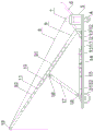
FIG. 1 is a schematic structural view of the present invention;
FIG. 2 is a side view;
in the figure: a base plate 1; a frame 2; a wheel 3; a universal wheel 4; a bracket 5; a handrail 6; a hoist 7; a wire rope 8; a lifting arm 9; a first fixed segment 91; a first telescopic section 92; a first positioning hole 10; a first bolt hole 11; a support 12; a horizontal support 13; a second fixed section 131; a second telescopic section 132; a second positioning hole 14; a second bolt hole 15; the first mounting lug 16; an oblique support 17; a second mounting lug 18; a pulley 19; a rotating shaft 20.
Detailed Description
The utility model is further described below with reference to the accompanying drawings and specific embodiments.
A pipe lifter mainly comprises a lifting arm 9 and a base. The base is composed of a frame 2 and a bottom plate 1, the bottom plate 1 is formed by welding square steel, the bottom plate 1 is fixedly welded above the frame 2, channel steel corresponding to a wheel axle is symmetrically arranged at the front end of the frame 2, the wheel axle is arranged on the frame 2 through the channel steel, and wheels 3 are arranged on the wheel axle; two universal wheels 4 are symmetrically arranged at the rear end of the frame 2.
The rear end of base sets up and utilizes the welding of square steel to have a bracket 5, and hoist engine 7 installs on bracket 5, and the rear side slant welding of bracket 5 has handrail 6. The front of the bracket 5 is provided with a support 12, the support 12 is provided with a lifting arm 9, the lifting arm 9 is of a telescopic structure, the lifting arm 9 consists of a first fixed section 91 and a telescopic section 92, the first fixed section 91 is of a hollow tubular structure, the lower end of the first fixed section 91 is hinged with the support 12 through a rotating shaft, and the outer wall of the first fixed section 91 is provided with a first positioning hole 10.
A plurality of first bolt holes 11 are formed in the outer wall of the first telescopic section 92 at intervals, the first telescopic section 92 extends from the upper end of the first fixed section 91, the first fixed section 91 is fixedly connected with the first telescopic section 92 through bolts inserted into the first positioning holes 10 and the first bolt holes 11, the first bolt holes 11 in different positions are adjusted to be aligned with the first positioning holes 10, and the length of the lifting arm 9 is adjusted.
The top end of the first telescopic section 92 is provided with a pulley 19, and a steel wire rope 8 of the winch 7 upwards rounds the pulley 19 along the lifting arm 9 and extends to the ground for pipe binding.
The horizontal support 13 is arranged along the length direction of the base, the rear end of the horizontal support 13 is fixedly connected with the support 12, the horizontal support 13 is also of a telescopic structure, the horizontal support is composed of a second fixed section 131 and a second telescopic section 132, the second fixed section 131 is also of a hollow tubular structure, a second positioning hole 14 is formed in the outer wall of the second fixed section 131, and the rear end of the second fixed section 131 is fixedly welded on the support 12.
A plurality of second bolt holes 15 are formed in the outer wall of the second telescopic section 132 at intervals, the rear end of the second telescopic section 132 is inserted into the front end of the second fixed section 131, the second fixed section 131 is fixedly connected with the second telescopic section 132 through bolts inserted into the second positioning holes 14 and the second bolt holes 15, and the second bolt holes 15 in different positions are adjusted to be aligned with the second positioning holes 14, so that the length of the horizontal support 13 is adjusted.
The lifting arm 9 and the horizontal support 13 are connected through an inclined support 17, a first mounting lug 16 is welded on the outer wall of the first fixed section 91, the upper end of the inclined support 17 is in bolted connection with the first mounting lug 16, a second mounting lug 18 is welded at the front end of the second telescopic section 132, and the lower section of the inclined support 17 is in bolted connection with the second mounting lug 18.
The length and height of the lifting arm can be adjusted through the telescopic sleeve structure, the pipe fitting device is suitable for installation operation of pipes with various heights, the installation is convenient, the construction period is shortened, the difficult problems of great self weight and difficult installation of the pipes are solved through the winch, the time and the labor can be saved, the installation efficiency is improved, the construction cost is reduced, and the construction progress is accelerated; moreover, the device is small in size, can work in places where hoisting tools cannot reach, is good in flexibility, is not limited by construction sites, and solves the problems that the sites are narrow and small and pipes are difficult to install.
The above description is only for the specific embodiment of the present invention, but the protection of the present invention is not limited thereto, and all equivalent changes or substitutions to the technical features of the present invention that can be made by those skilled in the art are included in the protection scope of the present invention.
Claims (3)
1. The utility model provides a tubular product lifting machine, includes lifing arm and base, its characterized in that: one end of the base is provided with a winch, one side of the winch is provided with a handrail, the other side of the winch is respectively provided with a lifting arm and a horizontal support, the lifting arm is arranged obliquely upwards, an oblique support is arranged between the horizontal support and the lifting arm, and two ends of the oblique support are respectively hinged with the horizontal support and the lifting arm; a pulley is arranged at the top end of the lifting arm, and a steel wire rope on the winch extends to the pulley along the lifting arm; one end of the base is provided with wheels, and the other end is provided with universal wheels.
2. The pipe hoist as claimed in claim 1, characterized in that: the lifting arm is of a telescopic structure, a first fixed section of the lifting arm is hinged with the support on the base, a first positioning hole is formed in the first fixed section of the lifting arm, and the upper end of the inclined support is hinged with the first fixed section; the first telescopic section of the lifting arm is provided with first bolt holes at intervals, and the first fixed section is connected with the first telescopic section through bolts arranged in the first positioning holes and the first bolt holes; and a pulley is arranged at the top of the first telescopic section.
3. The pipe hoist as claimed in claim 1, characterized in that: the horizontal support is of a telescopic structure, a second fixing section of the horizontal support is fixedly connected with the support on the base, and a second positioning hole is formed in the second fixing section; bolt holes II are formed in the telescopic section II of the horizontal support at intervals, and the fixed section II and the telescopic section II are connected through bolts arranged in the positioning holes II and the bolt holes II; the lower end of the inclined support is hinged with the second telescopic section.
Priority Applications (1)
| Application Number | Priority Date | Filing Date | Title |
|---|---|---|---|
| CN202122387569.6U CN215946554U (en) | 2021-09-30 | 2021-09-30 | Pipe elevator |
Applications Claiming Priority (1)
| Application Number | Priority Date | Filing Date | Title |
|---|---|---|---|
| CN202122387569.6U CN215946554U (en) | 2021-09-30 | 2021-09-30 | Pipe elevator |
Publications (1)
| Publication Number | Publication Date |
|---|---|
| CN215946554U true CN215946554U (en) | 2022-03-04 |
Family
ID=80425727
Family Applications (1)
| Application Number | Title | Priority Date | Filing Date |
|---|---|---|---|
| CN202122387569.6U Active CN215946554U (en) | 2021-09-30 | 2021-09-30 | Pipe elevator |
Country Status (1)
| Country | Link |
|---|---|
| CN (1) | CN215946554U (en) |
-
2021
- 2021-09-30 CN CN202122387569.6U patent/CN215946554U/en active Active
Similar Documents
| Publication | Publication Date | Title |
|---|---|---|
| CN202358849U (en) | Small-size suspension crane | |
| CN201263057Y (en) | Rack for paying off cable | |
| CN105003082A (en) | Glass curtain wall mounting equipment and glass curtain mounting method | |
| CN109252809B (en) | 10KV power transmission line foundation excavation device | |
| CN215946554U (en) | Pipe elevator | |
| CN213059942U (en) | Light simple hoisting equipment for sound barrier | |
| CN212599995U (en) | Welding installation equipment for hot-melt welded pipe | |
| CN213171204U (en) | Construction equipment hoisting device | |
| CN105819352B (en) | Lifting device for detachable door type mast building and construction method thereof | |
| CN209852461U (en) | Self-propelled pipeline transportation installation vehicle in corridor | |
| CN216945934U (en) | Double-rocker floor holding pole | |
| CN213475219U (en) | Roof concrete lifting and sliding conveying system | |
| CN206955487U (en) | It is exclusively used in lifting steel pipes and the crane device of welding | |
| CN206680096U (en) | One kind is used for restricted clearance hanging apparatus | |
| CN212769539U (en) | Universal portable maintenance lifting appliance for tower crane | |
| CN115613978A (en) | Vehicle-mounted workover rig vertical box type automatic minor repair operation integrated equipment and operation process | |
| CN212223029U (en) | Blast furnace down pipe spraying construction device | |
| CN210084786U (en) | Hoisting derrick mast | |
| JP5851774B2 (en) | Low head drilling rig with variable feed stroke | |
| CN212712397U (en) | Water pipe lifter | |
| CN220265089U (en) | Heavy pipeline mechanical lifting device | |
| CN217229938U (en) | Turning device of major diameter thin wall tuber pipe | |
| CN212356327U (en) | Traction device for dismounting and mounting large tower crane | |
| CN219314418U (en) | Lifting displacement device | |
| CN213294502U (en) | A hoisting support for installation of mine pipeline |
Legal Events
| Date | Code | Title | Description |
|---|---|---|---|
| GR01 | Patent grant | ||
| GR01 | Patent grant |