CN215545681U - High-performance submerged arc welding machine - Google Patents
High-performance submerged arc welding machine Download PDFInfo
- Publication number
- CN215545681U CN215545681U CN202121568252.6U CN202121568252U CN215545681U CN 215545681 U CN215545681 U CN 215545681U CN 202121568252 U CN202121568252 U CN 202121568252U CN 215545681 U CN215545681 U CN 215545681U
- Authority
- CN
- China
- Prior art keywords
- fixedly connected
- welding machine
- motor
- wall
- rod
- Prior art date
- Legal status (The legal status is an assumption and is not a legal conclusion. Google has not performed a legal analysis and makes no representation as to the accuracy of the status listed.)
- Active
Links
Images


Landscapes
- Arc Welding In General (AREA)
Abstract
The utility model provides a high-performance submerged arc welding machine, and relates to the technical field of submerged arc welding machines. According to the utility model, through the arrangement of the adjusting device, when the welding machine main body needs to be adjusted, the first motor is turned on, the welding machine main body moves in the horizontal direction, when the welding machine main body moves to a required position, the first motor is turned off, the second motor is turned on, and when the welding machine main body is lifted to the required position, the second motor is turned off, the welding machine main body welds a workpiece.
Description
Technical Field
The utility model relates to the technical field of submerged arc welding machines, in particular to a high-performance submerged arc welding machine.
Background
In the welding of workpiece members, submerged arc welding is used to weld the workpieces.
Most of existing submerged arc welding machines can only weld one position of a workpiece at a time, when the workpiece needs to be welded at multiple positions, the submerged arc welding machines need to be manually moved or the workpiece needs to be placed again, time and labor are wasted, working efficiency is reduced, one machine can only weld one workpiece at a time, welding efficiency is low, and therefore the high-performance submerged arc welding machine is provided.
SUMMERY OF THE UTILITY MODEL
The utility model aims to solve the defects in the prior art and provides a high-performance submerged arc welding machine.
In order to achieve the purpose, the utility model adopts the following technical scheme: a high-performance submerged arc welding machine comprises a workbench, wherein a welding machine body is arranged above the workbench, two groups of adjusting devices are arranged at the top of the workbench and used for adjusting the welding machine body, each adjusting device comprises an adjusting base fixedly connected with the top of the workbench, a first motor is fixedly connected with the inner wall of the adjusting base, a driving end of the first motor is rotatably connected with a threaded rod, one end of the threaded rod, far away from the first motor, is rotatably connected with the inner wall of the adjusting base through a bearing, the outer wall of the threaded rod is in threaded connection with a sliding block, the sliding block is slidably connected with the inner wall of the adjusting base, sliding rods are fixedly connected to two sides of the sliding block, one end of the sliding rod, far away from the sliding block, is fixedly connected with a lifting base, one side of the lifting base is fixedly connected with a second motor, and the driving end of the second motor is rotatably connected with a first rotating rod, the welding machine is characterized in that a rotating disc is fixedly connected to one end, away from the second motor, of the first rotating rod, a first connecting rod is fixedly connected to one side, away from the first rotating rod, of the rotating disc, a rotating plate is rotatably connected to one end, away from the rotating disc, of the first connecting rod through a bearing, and one end, away from the first connecting rod, of the rotating plate is rotatably connected with one side of the welding machine main body through a hinge.
Preferably, the inner wall fixedly connected with lifter of lift base, the outer wall sliding connection of lifter has the elevator, the bottom fixedly connected with sliding spring of elevator, sliding spring keeps away from the one end of elevator and lift base's inner wall sliding connection, one side fixedly connected with dead lever of sliding block, the one end of elevator and one side fixed connection of welding machine main part are kept away from to the dead lever.
Preferably, the four corners of the bottom of the workbench are fixedly connected with supporting legs, and the bottoms of the supporting legs are provided with anti-skid grains.
Preferably, the top of the workbench is provided with fixing devices which are arranged at equal intervals.
Preferably, fixing device include with workstation top fixed connection's unable adjustment base, unable adjustment base's top fixedly connected with fixed motor, fixed motor's drive end rotates and is connected with the worm, the one end that fixed motor was kept away from to the worm is passed through the bearing and is connected with the inner wall rotation of workstation, unable adjustment base's inner wall rotates through the bearing and is connected with the second dwang, the outer wall fixedly connected with worm wheel of second dwang, the worm wheel meshes with the worm mutually, two sets of fixed blocks of outer wall fixedly connected with of second dwang, one side fixedly connected with second connecting rod of fixed block, the one end fixedly connected with limiting plate of fixed block is kept away from to the second connecting rod, the bottom fixedly connected with gag lever post of limiting plate, the spacing post of one end fixedly connected with of limiting plate is kept away from to the gag lever post.
Preferably, a round hole is formed in the top of the fixed base and is matched with the worm.
Compared with the prior art, the utility model has the advantages and positive effects that:
1. in the utility model, through arranging the adjusting device, when the welding machine main body needs to be adjusted, the first motor is turned on to drive the threaded rod to rotate, so that the sliding block slides along with the threaded rod, the lifting base slides in the same direction, the welding machine main body moves in the horizontal direction, when the welding machine main body moves to a required position, the first motor is turned off, the second motor is turned on to drive the first rotating rod and the rotating disc to rotate, the first connecting rod and the rotating plate rotate simultaneously, the lifting block and the fixing rod slide, the sliding spring buffers, when the welding machine main body moves to the required position, the second motor is turned off, the welding machine main body welds a workpiece, the adjustment is completed, most of the existing submerged arc welding machines can only weld one part of the workpiece at each time, when the workpiece needs to be welded at multiple positions, the submerged arc welding machines need to be manually moved or the workpiece is put again, time and labor are wasted, and the working efficiency is reduced, and one machine can only weld one workpiece at a time, so that the welding processing efficiency is not high, and the application of the device effectively improves the practicability of the equipment.
2. According to the utility model, by arranging the fixing device, when the workpiece needs to be fixed, the fixing motor is started to drive the worm to rotate, meanwhile, the worm wheel and the second rotating rod rotate, so that the fixing block and the second connecting rod rotate together, the limiting plate and the limiting rod rotate in the same direction, the limiting column fixes the workpiece to complete the fixation, most of workpieces are fixed by bolts at present, tools such as a wrench and the like are needed for bolt fixation, the operation is complex, a large amount of time is consumed, and the device effectively improves the usability of equipment due to the application of the device.
Drawings
FIG. 1 is a schematic perspective view of a high performance submerged arc welding machine according to the present invention;
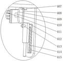
FIG. 2 is a partial cross-sectional view of an adjustment device in a high performance submerged arc welding machine according to the present invention;
FIG. 3 is a schematic view of a part of the structure of an adjusting device in a high performance submerged arc welding machine according to the present invention;
FIG. 4 is a schematic structural diagram of a fixing device in a high performance submerged arc welding machine according to the present invention.
Illustration of the drawings: 1. a work table; 2. supporting legs; 3. a welder body; 4. an adjustment device; 401. adjusting the base; 402. a first motor; 403. a slider; 404. a lifting base; 405. a slide bar; 406. a threaded rod; 407. a first connecting rod; 408. a rotating plate; 409. rotating the disc; 410. a first rotating lever; 411. a second motor; 412. a lifting block; 413. fixing the rod; 414. a slide spring; 415. a lifting rod; 5. a fixing device; 501. a fixed base; 502. a fixed block; 503. a limiting rod; 504. a limiting column; 505. a limiting plate; 506. a second connecting rod; 507. a second rotating lever; 508. a worm gear; 509. a worm; 510. and fixing the motor.
Detailed Description
In order that the above objects, features and advantages of the present invention can be more clearly understood, the present invention will be further described with reference to the accompanying drawings and examples. It should be noted that the embodiments and features of the embodiments of the present application may be combined with each other without conflict.
In the following description, numerous specific details are set forth in order to provide a thorough understanding of the present invention, however, the present invention may be practiced in other ways than those specifically described herein, and thus the present invention is not limited to the specific embodiments of the present disclosure.
Embodiment 1, as shown in fig. 1 to 4, the present invention provides a high performance submerged arc welding machine comprising a table 1, and a welding machine body 3 provided above the table 1.
The specific arrangement and function of the adjusting means 4 and the fixing means 5 will be described in detail below.
As shown in fig. 2 and fig. 3, two sets of adjusting devices 4 are disposed on the top of the workbench 1 and used for adjusting the welder body 3, each adjusting device 4 includes an adjusting base 401 fixedly connected to the top of the workbench 1, a first motor 402 is fixedly connected to the inner wall of the adjusting base 401, a threaded rod 406 is rotatably connected to the driving end of the first motor 402, one end of the threaded rod 406, which is far away from the first motor 402, is rotatably connected to the inner wall of the adjusting base 401 through a bearing, a sliding block 403 is threadedly connected to the outer wall of the threaded rod 406, the sliding block 403 is slidably connected to the inner wall of the adjusting base 401, sliding rods 405 are fixedly connected to both sides of the sliding block 403, a lifting base 404 is fixedly connected to one end of the sliding rod 405, which is far away from the sliding block 403, a second motor 411 is fixedly connected to one side of the lifting base 404, a first rotating rod 410 is rotatably connected to the driving end of the second motor 411, a rotating disc 409 is fixedly connected to one end of the first rotating rod 410, which is far away from the second motor 411, one side of the rotating disc 409 far away from the first rotating rod 410 is fixedly connected with a first connecting rod 407, one end of the first connecting rod 407 far away from the rotating disc 409 is rotatably connected with a rotating plate 408 through a bearing, one end of the rotating plate 408 far away from the first connecting rod 407 is rotatably connected with one side of the welding machine main body 3 through a hinge, an inner wall of the lifting base 404 is fixedly connected with a lifting rod 415, the outer wall of the lifting rod 415 is slidably connected with a lifting block 412, the bottom of the lifting block 412 is fixedly connected with a sliding spring 414, one end of the sliding spring 414 far away from the lifting block 412 is slidably connected with the inner wall of the lifting base 404, one side of the sliding block 403 is fixedly connected with a fixing rod 413, and one end of the fixing rod 413 far away from the lifting block 412 is fixedly connected with one side of the welding machine main body 3.
The whole adjusting device 4 achieves the effect that by arranging the adjusting device 4, when the welding machine main body 3 needs to be adjusted, the first motor 402 is turned on to drive the threaded rod 406 to rotate, so that the sliding block 403 slides together, the lifting base 404 slides in the same direction, the welding machine main body 3 moves in the horizontal direction, when the welding machine main body 3 moves to a required position, the first motor 402 is turned off, the second motor 411 is turned on to drive the first rotating rod 410 and the rotating disc 409 to rotate, the first connecting rod 407 and the rotating plate 408 rotate simultaneously, the lifting block 412 and the fixed rod 413 slide, the sliding spring 414 buffers, when the welding machine main body 3 moves to the required position, the second motor 411 is turned off, the welding machine main body 3 welds the workpiece, the adjustment is completed, most of the existing submerged arc welding machines can only weld one position of the workpiece at each time, when the workpiece needs to be welded at multiple positions, the submerged arc welding machines need to be moved manually or the workpiece needs to be put again, waste time and energy, reduce work efficiency to a machine platform can only weld a work piece once, makes welding process's efficiency not high, and the effectual practicality that has improved equipment of using of this device.
As shown in fig. 1 and 4, a fixing device 5 is arranged at the top of the workbench 1, the fixing device 5 is arranged at equal intervals, the fixing device 5 comprises a fixing base 501 fixedly connected with the top of the workbench 1, a fixing motor 510 is fixedly connected with the top of the fixing base 501, a worm 509 is rotatably connected with the driving end of the fixing motor 510, one end of the worm 509, which is far away from the fixing motor 510, is rotatably connected with the inner wall of the workbench 1 through a bearing, the inner wall of the fixing base 501 is rotatably connected with a second rotating rod 507 through a bearing, the outer wall of the second rotating rod 507 is fixedly connected with a worm wheel 508, the worm wheel 508 is meshed with the worm 509, two groups of fixing blocks 502 are fixedly connected with the outer wall of the second rotating rod 507, one side of the fixing block 502 is fixedly connected with a second connecting rod 506, one end of the second connecting rod 506, which is far away from the fixing block 502, is fixedly connected with a limiting plate 505, and the bottom of the limiting plate 505 is fixedly connected with a limiting rod 503, one end of the limiting rod 503, which is far away from the limiting plate 505, is fixedly connected with a limiting column 504, and a round hole is formed in the top of the fixing base 501 and is matched with the worm 509.
The effect that its whole fixing device 5 reaches does, through setting up fixing device 5, when the work piece needs to be fixed, open fixed motor 510, it rotates to drive worm 509, worm wheel 508 and second dwang 507 rotate simultaneously, make fixed block 502 and second connecting rod 506 rotate along with it, limiting plate 505 and gag lever post 503 syntropy rotate, spacing post 504 is fixed the work piece, it is fixed to accomplish, present most work pieces all adopt bolt fastening, tools such as spanner need be used in bolt fastening, the operation is complicated, need consume a large amount of time, the effectual ease for use that has improved equipment of this device.
The overall working principle is that when the welding machine main body 3 needs to be adjusted, the first motor 402 is turned on to drive the threaded rod 406 to rotate, so that the sliding block 403 slides together, the lifting base 404 slides in the same direction, the welding machine main body 3 moves in the horizontal direction, when the welding machine main body 3 moves to a required position, the first motor 402 is turned off, the second motor 411 is turned on to drive the first rotating rod 410 and the rotating disc 409 to rotate, the first connecting rod 407 and the rotating plate 408 rotate simultaneously, the lifting block 412 and the fixing rod 413 slide, the sliding spring 414 buffers, when the welding machine main body 3 moves to a required position, the second motor 411 is turned off, the welding machine main body 3 welds the workpiece, and adjustment is completed, most of existing submerged arc welding machines can only weld one position of the workpiece at a time, when a plurality of workpieces need to be welded, a submerged arc welding machine needs to be manually moved or the workpiece needs to be put again, waste time and energy, work efficiency is reduced, and a platform can only weld a work piece once, make welding process's efficiency not high, the effectual practicality that improves equipment of the application of this device, when the work piece needs to be fixed, open fixed motor 510, drive worm 509 and rotate, worm wheel 508 and second dwang 507 rotate simultaneously, make fixed block 502 and second connecting rod 506 rotate together thereupon, limiting plate 505 and gag lever post 503 syntropy rotate, spacing post 504 is fixed the work piece, it is fixed to accomplish, present most work pieces all adopt bolt fastening, instrument such as spanner need be used in bolt fastening, the operation is complicated, need consume a large amount of time, the effectual ease for use that improves equipment of application of this device.
The above description is only a preferred embodiment of the present invention, and not intended to limit the present invention in other forms, and any person skilled in the art may apply the above modifications or changes to the equivalent embodiments with equivalent changes, without departing from the technical spirit of the present invention, and any simple modification, equivalent change and change made to the above embodiments according to the technical spirit of the present invention still belong to the protection scope of the technical spirit of the present invention.
Claims (6)
1. A high performance submerged arc welding machine, includes workstation (1), its characterized in that: a welding machine main body (3) is arranged above the workbench (1), and two groups of adjusting devices (4) are arranged at the top of the workbench (1) and used for adjusting the welding machine main body (3);
the adjusting device (4) comprises an adjusting base (401) fixedly connected with the top of the workbench (1), the inner wall of the adjusting base (401) is fixedly connected with a first motor (402), the driving end of the first motor (402) is rotatably connected with a threaded rod (406), one end, far away from the first motor (402), of the threaded rod (406) is rotatably connected with the inner wall of the adjusting base (401) through a bearing, the outer wall of the threaded rod (406) is in threaded connection with a sliding block (403), the sliding block (403) is slidably connected with the inner wall of the adjusting base (401), two sides of the sliding block (403) are fixedly connected with sliding rods (405), one end, far away from the sliding block (403), of each sliding rod (405) is fixedly connected with a lifting base (404), one side of the lifting base (404) is fixedly connected with a second motor (411), the driving end of the second motor (411) is rotatably connected with a first rotating rod (410), one end fixedly connected with rolling disc (409) of second motor (411) is kept away from in first rotation pole (410), one side fixedly connected with head rod (407) of first rotation pole (410) are kept away from in rolling disc (409), the one end that head rod (407) kept away from rolling disc (409) is rotated through the bearing and is connected with rotating plate (408), rotating plate (408) are kept away from the one end of head rod (407) and are passed through the hinge and are connected with the rotation of one side of welding machine main part (3).
2. A high performance submerged arc welding machine according to claim 1, characterized in that: inner wall fixedly connected with lifter (415) of lift base (404), the outer wall sliding connection of lifter (415) has elevator (412), the bottom fixedly connected with sliding spring (414) of elevator (412), the one end that elevator (412) were kept away from in sliding spring (414) and the inner wall sliding connection of lift base (404), one side fixedly connected with dead lever (413) of sliding block (403), one side fixed connection of elevator (412) and welder main part (3) are kept away from in dead lever (413).
3. A high performance submerged arc welding machine according to claim 1, characterized in that: the four corners of the bottom of the workbench (1) are fixedly connected with supporting legs (2), and anti-skid grains are arranged at the bottoms of the supporting legs (2).
4. A high performance submerged arc welding machine according to claim 1, characterized in that: the top of workstation (1) is provided with fixing device (5), fixing device (5) are the equidistant setting.
5. A high performance submerged arc welding machine according to claim 4, characterized in that: the fixing device (5) comprises a fixing base (501) fixedly connected with the top of the workbench (1), a fixing motor (510) is fixedly connected to the top of the fixing base (501), a worm (509) is rotatably connected to the driving end of the fixing motor (510), one end, far away from the fixing motor (510), of the worm (509) is rotatably connected with the inner wall of the workbench (1) through a bearing, the inner wall of the fixing base (501) is rotatably connected with a second rotating rod (507) through a bearing, the outer wall of the second rotating rod (507) is fixedly connected with a worm wheel (508), the worm wheel (508) is meshed with the worm (509), the outer wall of the second rotating rod (507) is fixedly connected with two groups of fixing blocks (502), one side of the fixing block (502) is fixedly connected with a second connecting rod (506), and one end, far away from the second connecting rod (506), of the fixing block (502) is fixedly connected with a limiting plate (505), the bottom of the limiting plate (505) is fixedly connected with a limiting rod (503), and one end, far away from the limiting plate (505), of the limiting rod (503) is fixedly connected with a limiting column (504).
6. A high performance submerged arc welding machine according to claim 5, characterized in that: the top of the fixed base (501) is provided with a round hole, and the round hole is matched with the worm (509).
Priority Applications (1)
| Application Number | Priority Date | Filing Date | Title |
|---|---|---|---|
| CN202121568252.6U CN215545681U (en) | 2021-07-12 | 2021-07-12 | High-performance submerged arc welding machine |
Applications Claiming Priority (1)
| Application Number | Priority Date | Filing Date | Title |
|---|---|---|---|
| CN202121568252.6U CN215545681U (en) | 2021-07-12 | 2021-07-12 | High-performance submerged arc welding machine |
Publications (1)
| Publication Number | Publication Date |
|---|---|
| CN215545681U true CN215545681U (en) | 2022-01-18 |
Family
ID=79824858
Family Applications (1)
| Application Number | Title | Priority Date | Filing Date |
|---|---|---|---|
| CN202121568252.6U Active CN215545681U (en) | 2021-07-12 | 2021-07-12 | High-performance submerged arc welding machine |
Country Status (1)
| Country | Link |
|---|---|
| CN (1) | CN215545681U (en) |
-
2021
- 2021-07-12 CN CN202121568252.6U patent/CN215545681U/en active Active
Similar Documents
| Publication | Publication Date | Title |
|---|---|---|
| CN113580079A (en) | Turnover operation table for sheet metal welding six-axis manipulator | |
| CN215545681U (en) | High-performance submerged arc welding machine | |
| CN206561416U (en) | A kind of Novel machine frame type mechanical arm | |
| CN211220697U (en) | Novel intelligent robot equipment | |
| KR20130069943A (en) | Automatic conversion workbench | |
| CN210475967U (en) | Improved welding tool fixture | |
| CN216177818U (en) | Rotating mechanism for welding robot | |
| CN214868392U (en) | Light welding transformer | |
| CN212601692U (en) | Machining fixed station | |
| CN215033994U (en) | Stainless steel rim cutting machine for machining children bicycle wheels | |
| CN215146322U (en) | Welding device | |
| CN220498294U (en) | Welding positioning device for automobile production | |
| CN205968224U (en) | A planer -type milling machine for milling processing forging | |
| CN220863093U (en) | Welding equipment for overturning bracket | |
| CN218592232U (en) | Welding equipment | |
| CN212552463U (en) | Position changing machine | |
| CN219426585U (en) | Bearing mechanism and bench vice | |
| CN220839869U (en) | Workpiece positioning mechanism of machining center | |
| CN212825017U (en) | Screw locking jig | |
| CN220592962U (en) | Rear frame assembly tooling structure | |
| CN219522067U (en) | Mechanical clamp convenient to adjust flexibly | |
| CN217224670U (en) | Truss robot and cylinder sleeve finish machining production line | |
| CN220774175U (en) | Distribution switch production frock | |
| CN214237837U (en) | Automobile hand plate workpiece machining and clamping mechanism | |
| CN219429669U (en) | Intelligent chemical industry capable of automatically overturning |
Legal Events
| Date | Code | Title | Description |
|---|---|---|---|
| GR01 | Patent grant | ||
| GR01 | Patent grant |