CN215533350U - Combined gardening flower stand - Google Patents
Combined gardening flower stand Download PDFInfo
- Publication number
- CN215533350U CN215533350U CN202122108504.3U CN202122108504U CN215533350U CN 215533350 U CN215533350 U CN 215533350U CN 202122108504 U CN202122108504 U CN 202122108504U CN 215533350 U CN215533350 U CN 215533350U
- Authority
- CN
- China
- Prior art keywords
- supporting
- support frame
- limiting
- flowerpot
- water
- Prior art date
- Legal status (The legal status is an assumption and is not a legal conclusion. Google has not performed a legal analysis and makes no representation as to the accuracy of the status listed.)
- Active
Links
Images


Abstract
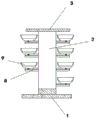
The utility model discloses a combined type gardening flower stand, which comprises a base for supporting, wherein a water pump for irrigation is connected onto the base through bolts and nuts, an L-shaped water pipe is fixedly and hermetically connected onto a water outlet of the water pump, a plurality of shower type nozzles with the same specification for watering are fixedly and hermetically arranged on the L-shaped water pipe, a plurality of supporting plates for supporting a flowerpot device are fixedly arranged on a supporting frame, a moving device for driving the flowerpot device to move is fixedly arranged on each supporting plate, and the flowerpot device is fixedly arranged at the upper end of the moving device, can realize the functions of shading sun and keeping off rain.
Description
Technical Field
The utility model relates to the technical field of flower stands, in particular to a combined gardening flower stand.
Background
The flower shelf is also called green corridor, flower corridor, pergola, etc., is a small article facility which is formed by upright posts and a structure with grid strips at the top and can make vine plants climb and cover, in green lands of various gardens, the flower shelf is expressed by its active shape, color and plants, jointly creates a landscape space which integrates the use function and scenery viewing and admiring, etc.,
present horticulture pergola planting rate is low, and under the condition that satisfies the planting rate, the long space of peanut dwindles, and illumination intensity and time reduce, is unfavorable for growing development, and during sunshine intensity is too big or rainy, can't realize carrying out the sunshade and keeping off the rain to cause the mortality to rise, and be unfavorable for the management, the aesthetic property is relatively poor.
SUMMERY OF THE UTILITY MODEL
The present invention is directed to a combined gardening flower shelf to solve the above problems.
In order to achieve the purpose, the utility model provides the following technical scheme: the method is characterized in that: including the base that is used for the supporting role, the fixed support frame that is provided with in base upper end, the support frame is the semicircle type, the fixed roof that is used for sheltering from the effect that is provided with in support frame upper end, bolt and nut is connected with the water pump that is used for the irrigation effect on the base, water pump delivery port fixed seal is connected with L type water pipe, fixed seal is provided with the gondola water faucet formula shower nozzle that is used for watering that a plurality of specifications are the same on the L type water pipe, the fixed backup pad that is used for supporting the flowerpot device that is provided with on the support frame, the fixed mobile device that is used for driving the flowerpot device and removes that is provided with in the backup pad, the fixed flowerpot device that is provided with in mobile device upper end.
The technical scheme is that in the using process: can change the position of flowerpot device as required through mobile device, satisfy the needs of different scenes, the crisscross both sides that move of flowerpot device simultaneously increases illumination area and growing space, when rainy day or illumination intensity are too big, can move flowerpot device 9 under roof 3, can realize the effect of sunshade and rain-proof.
Preferably, the base is provided with a screw hole, and the base 1 is fixed by passing a bolt through the screw hole.
Preferably, the upper end of the L-shaped water pipe is fixed at the lower end of the top plate.
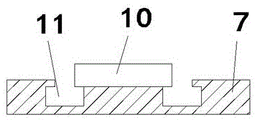
Preferably, be equipped with the lug of fixing in the backup pad up end on the mobile device, the lug both sides are located and are provided with the slip recess that is used for the slip supporting role in the backup pad, slip recess quantity is two, and is the symmetric distribution about the lug, the transversal 'concave' font of personally submitting of slip recess, sliding connection has the sliding block in the slip recess, the sliding block is corresponding with the slip recess, the fixed recess that is provided with corresponding with the lug on the sliding block, the recess is located the lug upper end, the recess is connected for sliding mode with the lug, the fixed spacing hole that is used for a plurality of specifications of limiting role is the same that is provided with in lug one side, be provided with two stop device around corresponding with spacing hole on the recess.
Preferably, the flowerpot device lower extreme is fixed directly over the recess, the flowerpot device is provided with the first support frame that is used for the supporting role, first support frame is the hemisphere type, first support frame lower extreme central axis rigidity is provided with and is used for supporting spacing post, first support frame lower half is for the aqua storage tank that is used for the water storage, be provided with the drain pipe that is used for the aqua storage tank water yield when too big around the first support frame outside, first support frame internalization is provided with the second support frame that is used for planting flowers, the second support frame is corresponding with first support frame, terminal surface is provided with the spacing recess corresponding with spacing post under the second support frame, second support frame lower extreme is provided with the waterlogging caused by excessive rainfall hole.
Preferably, the upper end of the drain pipe is communicated with the water storage tank, and the lower end of the drain pipe is provided with a water outlet.
Compared with the prior art, the utility model has the beneficial effects that: the utility model relates to a combined type gardening flower stand, wherein the position of a flowerpot device can be changed according to the needs through a moving device, the needs of different scenes are met, meanwhile, the flowerpot device moves towards two sides in a staggered mode, the illumination area and the growth space are increased, when rainy days or the illumination intensity is too high, the flowerpot device 9 can be moved to the position under a top plate 3, and the effects of shading sun and shielding rain can be realized.
Drawings
Fig. 1 is a schematic structural view of the assembled gardening flower stand according to the present invention.
Fig. 2 is a side view of the assembled gardening flower stand according to the present invention.
Fig. 3 is a top view of the assembled gardening flower shelf of the present invention.
Fig. 4 is a schematic structural view of the combined type gardening flower shelf moving device according to the present invention.
Fig. 5 is a schematic structural view of the sliding groove of the combined gardening flower shelf moving device according to the present invention.
FIG. 6 is a side view of the projection of the assembled gardening flower shelf of the present invention.
Fig. 7 is a schematic view illustrating a groove structure of the combined type gardening flower shelf moving device according to the present invention.
Fig. 8 is a schematic structural view of the combined type gardening flower stand flowerpot device of the present invention.
In the figure: 1-base, 2-support shelf, 3-top plate, 4-water pump, 5-L-shaped water pipe, 6-shower head, 7-support plate, 8-moving device, 9-flowerpot device, 10-lug, 11-sliding groove, 12-sliding block, 13-groove, 14-limiting device, 15-limiting hole, 16-first support shelf, 17-water storage groove, 18-drain pipe, 19-limiting column, 20-second support shelf, 21-limiting groove.
Detailed Description
The technical solutions in the embodiments of the present invention will be clearly and completely described below with reference to the drawings in the embodiments of the present invention, and it is obvious that the described embodiments are only a part of the embodiments of the present invention, and not all of the embodiments. All other embodiments, which can be derived by a person skilled in the art from the embodiments given herein without making any creative effort, shall fall within the protection scope of the present invention.
Referring to fig. 1-8, the present invention provides a technical solution: the method is characterized in that: the water-saving watering device comprises a base 1 for supporting, wherein a screw hole is formed in the base 1, a bolt penetrates through the screw hole to fix the base 1, a support frame 2 is fixedly arranged at the upper end of the base 1, the support frame 2 is in a semicircular shape, a top plate 3 for shielding, is fixedly arranged at the upper end of the support frame 2, a water pump 4 for irrigation is connected to the base 1 through a bolt and a nut, a water inlet of the water pump 4 is connected with a tap water pipe, a water outlet of the water pump 4 is fixedly and hermetically connected with an L-shaped water pipe 5, the upper end of the L-shaped water pipe 5 is fixedly arranged at the lower end of the top plate 3, a plurality of shower type nozzles 6 with the same specification and used for watering are fixedly and hermetically arranged on the L-shaped water pipe 5, when the water-saving watering device is used, water is conveyed to the shower type nozzles 6 through the L-shaped water pipe 5, and the watering effect is realized through the shower type nozzles 6;
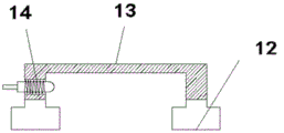
the flowerpot device comprises a supporting frame 2, a plurality of supporting plates 7 for supporting flowerpot devices 9 are fixedly arranged on the supporting frame 2, a moving device 8 for driving the flowerpot devices 9 to move is fixedly arranged on the supporting plates 7, convex blocks 10 fixed on the upper end surface of the supporting plates 7 are arranged on the moving device 8, sliding grooves 11 for sliding supporting are arranged on the supporting plates 7 at two sides of the convex blocks 10, the number of the sliding grooves 11 is two, the sliding grooves are symmetrically distributed relative to the convex blocks 10, the cross sections of the sliding grooves 11 are shaped like 'concave', sliding blocks 12 are slidably connected in the sliding grooves 11, the sliding blocks 12 correspond to the sliding grooves 11, grooves 13 corresponding to the convex blocks 10 are fixedly arranged on the sliding blocks 12, the grooves 13 are arranged at the upper ends of the convex blocks 10, the grooves 13 are connected with the convex blocks 10 in a sliding mode, and a plurality of limiting holes 15 with the same specification and used for limiting are fixedly arranged on one side of the convex blocks 10, the groove 13 is provided with a front limiting device 14 and a rear limiting device 14 corresponding to the limiting holes 15, when the flowerpot is used, the limiting effect on the limiting holes 15 is relieved through the limiting devices 14, the groove 13 is dragged, the groove 13 slides along the convex block 10, meanwhile, the sliding block 12 is driven to move along the sliding groove 11, the convex block 10 and the sliding groove 11 realize the supporting and limiting effect, so that the position of the flowerpot device 9 on the groove 13 is changed, the flowerpot device 9 can be conveniently adjusted, the flowerpot devices 9 can move towards two sides in a staggered mode, the illumination area and the growth space are increased, when the rainy day or the illumination intensity is overlarge, the flowerpot device 9 can be moved to be under the top plate 3, and the effects of shading sun and shielding rain can be realized;
the limiting device 14 is in the prior art, and a limiting pin on the limiting device 14 is inserted into a limiting hole to limit and fix the groove and the bump;
the upper end of the moving device 8 is fixedly provided with a flowerpot device 9, the lower end of the flowerpot device 9 is fixed right above the groove 13, the flowerpot device 9 is provided with a first support frame 16 for supporting, the first support frame 16 is hemispherical, the lower end central axis of the first support frame 16 is fixedly provided with a limiting column 19 for supporting and limiting, the lower half part of the first support frame 16 is a water storage tank 17 for storing water, a drain pipe 18 for storing excessive water in the water storage tank 17 is arranged around the outer side of the first support frame 16, the upper end of the drain pipe 18 is communicated with the water storage tank 17, the lower end of the cable tiger drain pipe 18 is provided with a water outlet, a second support frame 20 for planting flowers is movably arranged in the first support frame 16, the second support frame 20 corresponds to the first support frame 16, and the lower end surface of the second support frame 20 is provided with a limiting groove 21 corresponding to the limiting column 19, the lower extreme of second support frame 20 is provided with the waterlogging caused by excessive rainfall hole, during the use, installs second support frame 20 in first support frame 16, inserts spacing post 19 in spacing recess 21, realizes planting the flower through second support frame 20, is used for the storage water in the aqua storage tank 17, when watering, in water permeates the aqua storage tank 17 through the soil on the second support frame 20, discharges through drain pipe 18 when the aqua storage tank 17 internal water volume is too much.
The working principle of the utility model is as follows: the water is conveyed to the shower nozzle 6 through the L-shaped water pipe 5 by the operation of the water pump 4, the watering effect is realized through the shower nozzle 6, the second support frame 20 is arranged in the first support frame 16, the limiting column 19 is inserted into the limiting groove 21, the planting of flowers is realized through the second support frame 20, the water storage tank 17 is used for storing water, when watering is carried out, the water permeates into the water storage tank 17 through the soil on the second support frame 20, when the water amount in the water storage tank 17 is excessive, the water is discharged through the water discharge pipe 18, the limiting effect on the limiting hole 15 is relieved through the limiting device 14, the groove 13 is dragged, the groove 13 slides along the convex block 10, the sliding block 12 is driven to move along the sliding groove 11, the supporting and limiting effects are realized by the convex block 10 and the sliding groove 11, so that the position of the flowerpot device 9 on the groove 13 is changed, the adjustment is convenient, and the flowerpot device 9 moves towards two sides in a staggered way, increase illumination area and the space of growing, when rainy day or illumination intensity are too big, can move flowerpot device 9 under roof 3, can realize the effect of sunshade and rain-proof.
It will be evident to those skilled in the art that the utility model is not limited to the details of the foregoing illustrative embodiments, and that the present invention may be embodied in other specific forms without departing from the spirit or essential attributes thereof. The present embodiments are therefore to be considered in all respects as illustrative and not restrictive, the scope of the utility model being indicated by the appended claims rather than by the foregoing description, and all changes which come within the meaning and range of equivalency of the claims are therefore intended to be embraced therein. Any reference sign in a claim should not be construed as limiting the claim concerned.
Claims (6)
1. A modular horticulture pergola which characterized in that: comprises a base (1) for supporting, a supporting frame (2) is fixedly arranged at the upper end of the base (1), the supporting frame (2) is in a semicircular shape, a top plate (3) for shielding is fixedly arranged at the upper end of the supporting frame (2), a water pump (4) for irrigation is connected onto the base (1) through bolts and nuts, an L-shaped water pipe (5) is fixedly and hermetically connected with a water outlet of the water pump (4), a plurality of shower type nozzles (6) with the same specification and used for watering are fixedly and hermetically arranged on the L-shaped water pipe (5),
the flowerpot support is characterized in that a plurality of supporting plates (7) used for supporting the flowerpot devices (9) are fixedly arranged on the supporting frame (2), a moving device (8) used for driving the flowerpot devices (9) to move is fixedly arranged on the supporting plates (7), and the flowerpot devices (9) are fixedly arranged at the upper ends of the moving devices (8).
2. The modular horticultural planter stand of claim 1, wherein: the base (1) is provided with a screw hole, and the base (1) is fixed by penetrating the screw hole through a bolt.
3. The modular horticultural planter stand of claim 2, wherein: the upper end of the L-shaped water pipe (5) is fixed at the lower end of the top plate (3).
4. A modular horticultural planter according to claim 3, characterised in that: the mobile device (8) is provided with a convex block (10) fixed on the upper end surface of the support plate (7), the two sides of the convex block (10) are positioned on the support plate (7) and are provided with sliding grooves (11) used for sliding and supporting, the number of the sliding grooves (11) is two, the sliding grooves (11) are symmetrically distributed relative to the convex block (10), the cross section of each sliding groove (11) is in a concave shape, sliding blocks (12) are connected in the sliding grooves (11), the sliding blocks (12) correspond to the sliding grooves (11), grooves (13) corresponding to the convex blocks (10) are fixedly arranged on the sliding blocks (12), the grooves (13) are positioned at the upper ends of the convex blocks (10), the grooves (13) are connected with the convex blocks (10) in a sliding mode, one side of the convex block (10) is fixedly provided with a plurality of limiting holes (15) with the same specification and used for limiting, the groove (13) is provided with a front limiting device and a rear limiting device (14) corresponding to the limiting hole (15).
5. The modular horticultural planter stand of claim 4, wherein: the lower end of the flowerpot device (9) is fixed right above the groove (13), the flowerpot device (9) is provided with a first supporting frame (16) for supporting, the first support frame (16) is hemispherical, a limiting column (19) for supporting and limiting is fixedly arranged at the central axis position of the lower end of the first support frame (16), the lower half part of the first support frame (16) is a water storage tank (17) used for storing water, a drain pipe (18) used when the water amount of the water storage tank (17) is overlarge is arranged around the outer side of the first supporting frame (16), a second support frame (20) for planting flowers is movably arranged in the first support frame (16), the second support frame (20) is corresponding to the first support frame (16), a limiting groove (21) corresponding to the limiting column (19) is formed in the lower end face of the second support frame (20), and a water draining hole is formed in the lower end of the second support frame (20).
6. The modular horticultural planter stand of claim 5, wherein: the upper end of the drain pipe (18) is communicated with the water storage tank (17), and the lower end of the drain pipe (18) is provided with a water outlet.
Priority Applications (1)
| Application Number | Priority Date | Filing Date | Title |
|---|---|---|---|
| CN202122108504.3U CN215533350U (en) | 2021-09-02 | 2021-09-02 | Combined gardening flower stand |
Applications Claiming Priority (1)
| Application Number | Priority Date | Filing Date | Title |
|---|---|---|---|
| CN202122108504.3U CN215533350U (en) | 2021-09-02 | 2021-09-02 | Combined gardening flower stand |
Publications (1)
| Publication Number | Publication Date |
|---|---|
| CN215533350U true CN215533350U (en) | 2022-01-18 |
Family
ID=79846207
Family Applications (1)
| Application Number | Title | Priority Date | Filing Date |
|---|---|---|---|
| CN202122108504.3U Active CN215533350U (en) | 2021-09-02 | 2021-09-02 | Combined gardening flower stand |
Country Status (1)
| Country | Link |
|---|---|
| CN (1) | CN215533350U (en) |
-
2021
- 2021-09-02 CN CN202122108504.3U patent/CN215533350U/en active Active
Similar Documents
| Publication | Publication Date | Title |
|---|---|---|
| CN213784587U (en) | Special water-saving irrigation device of horticulture flowers | |
| CN215533350U (en) | Combined gardening flower stand | |
| CN213907645U (en) | Agricultural three-dimensional cultivation device | |
| CN212212079U (en) | Fruit tree device of growing seedlings for agricultural production | |
| CN212876937U (en) | Fruit tree seed seedling raising equipment | |
| CN113892365A (en) | Can collect campus view combination formula flowers and plants planting device of rainwater | |
| CN212786921U (en) | Municipal garden is with rack cultivated in a pot | |
| CN212876901U (en) | Landscape plant is with supplementary growth device of climbing formula plant | |
| CN211960265U (en) | Environment-friendly water-saving landscaping device | |
| CN103321275B (en) | Combined comprehensive roof rainwater utilization system for landscaping | |
| CN213757596U (en) | Horticulture potted plant show shelf | |
| CN210695182U (en) | Greening device for ecological environment-friendly engineering | |
| CN220044291U (en) | Modeling-changeable greening device for landscape architecture | |
| CN218862207U (en) | Ecological pavilion | |
| CN218244689U (en) | Three-dimensional planting device and building structure applying same | |
| CN216600949U (en) | Dragon fruit is planted with device of growing seedlings | |
| CN218934036U (en) | Ecological guardrail of gardens design | |
| CN218388896U (en) | Plant cultivation frame provided with lifting adjusting mechanism | |
| CN211324163U (en) | Gardens are with group shape pergola of being convenient for watering | |
| CN210868946U (en) | Horticulture arrangement frame cultivated in a pot | |
| CN217184183U (en) | Automatic irrigation equipment of horticulture | |
| CN218680401U (en) | Landscape pergola | |
| CN215602201U (en) | Strawberry planting greenhouse easy to install | |
| CN214461904U (en) | Green roof runoff water supply and drainage device | |
| CN220511768U (en) | Be used for three-dimensional cultivation device of gardens space plant |
Legal Events
| Date | Code | Title | Description |
|---|---|---|---|
| GR01 | Patent grant | ||
| GR01 | Patent grant |