CN214870863U - Automatic peeling device for cable - Google Patents
Automatic peeling device for cable Download PDFInfo
- Publication number
- CN214870863U CN214870863U CN202120915664.6U CN202120915664U CN214870863U CN 214870863 U CN214870863 U CN 214870863U CN 202120915664 U CN202120915664 U CN 202120915664U CN 214870863 U CN214870863 U CN 214870863U
- Authority
- CN
- China
- Prior art keywords
- cutting
- support
- transmission
- bits
- clamping
- Prior art date
- Legal status (The legal status is an assumption and is not a legal conclusion. Google has not performed a legal analysis and makes no representation as to the accuracy of the status listed.)
- Active
Links
Images


Landscapes
- Removal Of Insulation Or Armoring From Wires Or Cables (AREA)
Abstract
The utility model discloses an automatic device of peeling of cable belongs to power equipment technical field. The cable automatic peeling device comprises a support, a clamping and feeding mechanism, a cutting mechanism and a transmission mechanism, wherein the clamping and feeding mechanism is located at the front part of the cutting mechanism, the transmission mechanism is located at the lower part of the support, the support comprises four support legs and a supporting surface, the four support legs are fixed on the supporting surface in a welding mode, the transmission mechanism drives the clamping and feeding mechanism through chain transmission, and drives the cutting mechanism to cut in a rotating mode through belt transmission. The utility model provides a current cable device of peeling degree of automation low, the problem of inefficiency.
Description
Technical Field
The utility model relates to a power equipment technical field, concretely relates to automatic device of peeling of cable.
Background
When the insulated cable is subjected to defect eliminating operation, the outer skin of the insulated cable needs to be peeled off, and then follow-up operation is carried out.
The device comprises a clamping mechanism, a transverse moving rotating mechanism and a cutting mechanism, wherein the clamping mechanism comprises a clamping body, a clamping bolt and a clamping arc-shaped plate, the transverse moving rotating mechanism comprises a threaded rod, a rotating gear, a rotating shaft and a fixed box body, and a rocker is arranged at the front end of the rotating shaft; the cutting mechanism comprises a second L-shaped support, longitudinal cutting knives, a peeling guide mechanism and two groups of circumferential cutting assemblies, the peeling guide mechanism comprises two guide rollers, and each group of circumferential cutting assemblies comprises a guide rod, circumferential cutting knives, a first jacking bolt and a jacking spring. The present invention is awkward in design and not highly automated, and therefore, is hindered in use.
Disclosure of Invention
In view of this, the utility model aims to solve the technical problem that an automatic device of peeling of cable is provided, improved the degree of automation of equipment effectively, reduced staff's intensity of labour, improve work efficiency.
In order to solve the technical problem, the utility model discloses a following technical scheme:
the cable automatic peeling device comprises a support, a clamping and feeding mechanism, a cutting mechanism and a transmission mechanism, wherein the clamping and feeding mechanism is positioned in the front of the cutting mechanism, the transmission mechanism is positioned at the lower part of the support, the support comprises four support legs and a supporting surface, the four support legs are fixed on the supporting surface through welding, the transmission mechanism drives the clamping and feeding mechanism through chain transmission and drives the cutting mechanism to cut in a rotating mode through belt transmission.
The clamping and feeding mechanism comprises a mounting seat, a clamping execution mechanism and a chain wheel, the clamping execution mechanism is installed on the mounting seat, the clamping execution mechanism comprises an upper pushing rotating wheel, a lower pushing rotating wheel, a sliding block and a spring column, the upper pushing rotating wheel is externally connected with the chain wheel, the chain wheel is connected with the transmission mechanism through a chain, the lower pushing rotating wheel is connected with the sliding block, the sliding block is movably embedded on the mounting seat, and the lower part of the sliding block is connected with the spring column.
The cutting mechanism comprises a cutting motor, a cutter shaft, a cutting quantity auxiliary protection plate, a tension spring, a balance block, a belt disc, a support frame and a sleeve, wherein the belt disc is sleeved on the sleeve, the belt disc is connected with the transmission mechanism through transmission of a transmission belt, the sleeve is fixed on the support frame, the support frame is fixed on the upper end face of the support, the output end of the cutting motor is connected with the cutter shaft, the cutting quantity auxiliary protection plate is fixed on the outer side of the cutting motor, the end part of the cutting quantity auxiliary protection plate is movably connected with the balance block through the tension spring, and the balance block is fixed on the belt disc.
The cutter shaft is fixedly connected with a fan, and the wind of the fan blows to the cutting surface of the cutter shaft.
Still include and store up the bits device, it is located to store up the bits device the lower part of cutting mechanism, it includes the bits pipe and stores up the bits box to store up the bits device, the hollow plastic hose is adopted to the bits pipe, infundibulate collection bits mouth is connected to the one end of bits pipe, the upper end embedded of collection bits mouth on the support, and be located the lower part of arbor, it is the cuboid structure to store up the bits box.
The utility model has the advantages that: the utility model realizes the automatic function of feeding, cutting and dust removing as a whole by arranging the clamping and feeding mechanism, the cutting mechanism, the transmission mechanism and the scrap storage device, and effectively improves the working efficiency; the clamping and feeding mechanism utilizes a spring clamping force adjusting device, so that the cable can be firmly clamped no matter how thick the cable is, and the cable can be sent into the cutting mechanism; the cutter shaft in the cutting mechanism rotates and rotates along with the belt disc in a circumferential manner, so that the peeling range is enlarged, and the peeling efficiency is improved; the fan arranged on the cutter shaft can fully blow the cutting chips into the chip collecting opening of the chip removing pipe and slide into the chip storage box through the chip removing pipe; the utility model discloses stable in structure, peel totally, the noise is little, consequently is fit for extensively promoting.
Drawings
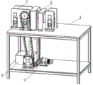
Fig. 1 is a schematic structural view of the automatic peeling device for cables of the present invention.
Fig. 2 is a schematic structural view of the clamping and feeding mechanism of the present invention.
Fig. 3 is the schematic view of the full-section structure of the cutting mechanism of the present invention.
Fig. 4 is a schematic view of a partial structure of the cutting mechanism of the present invention.
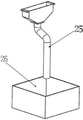
Fig. 5 is a schematic structural view of the scrap storage device of the present invention.
Detailed Description
The invention is further described with reference to the following figures and examples.
In order to make the purpose, technical solution and advantages of the embodiments of the present invention clearer, the following description will be made with reference to fig. 1 to 5 of the embodiments of the present invention to clearly and completely describe the technical solution of the embodiments of the present invention. It is to be understood that the embodiments described are only some of the embodiments of the present invention, and not all of them. All other embodiments, which can be derived from the description of the embodiments of the present invention by a person skilled in the art, are within the scope of the present invention.
In fig. 1 to 5, the reference numerals denote:
1. a support; 2. a clamping and feeding mechanism; 3. a cutting mechanism; 4. a transmission mechanism; 5. a scrap storage device; 6. a mounting seat; 7. pushing up the rotating wheel; 8. pushing down the runner; 9. a slider; 10. a spring post; 11. cutting the motor; 12. a cutter shaft; 13. a cutting amount auxiliary guard plate; 14. a tension spring; 15. a counterbalance; 16. a reel; 17. a support frame; 18. a sleeve; 19. a rotating base; 20. an arc limiting groove; 21. a limit screw; 22. a fan; 23. a circular arc plate; 24. a cable; 25. a dandruff removing pipe; 26. a crumb storage box.
The first embodiment is as follows:
the automatic cable peeling device shown in fig. 1 comprises a support 1, a clamping and feeding mechanism 2, a cutting mechanism 3 and a transmission mechanism 4, wherein the transmission mechanism 4 only provides power and torque through a motor, the transmission is mainly realized through a roller, a chain transmission and a V-belt transmission, and the motor is connected with two parts, namely a V-belt and a speed reducer. The cutting mechanism 3 is driven by the V-shaped belt through the motor to provide power and torque, so that the cable 24 is rotationally peeled; in addition, the motor changes the running speed through the speed reducer, and then provides torque and power to the upper pushing rotating wheel of the clamping and feeding mechanism 2 through chain transmission, so as to clamp the cable 24 and send the cable into and out of the cutting mechanism 3.
As shown in fig. 2, the clamping and feeding mechanism 2 comprises a mounting seat 6, a clamping execution mechanism and a chain wheel, the clamping execution mechanism is installed on the mounting seat 6, the clamping execution mechanism comprises an upper pushing rotating wheel 7, a lower pushing rotating wheel 8, a sliding block 9 and a spring column 10, the upper pushing rotating wheel 7 and the lower pushing rotating wheel 8 are both two, the inner side of the clamping execution mechanism is an external chain wheel of the upper pushing rotating wheel 7, the chain wheel is connected with the transmission mechanism 4 through a chain, the lower pushing rotating wheel is connected with the sliding block, the sliding block is embedded on the mounting seat, and the spring column is connected on the sliding block. Due to the action of the spring column 10, the sliding block 9 drives the lower pushing rotating wheel 8 to stretch up and down and tightly adhere to the surface of the cable 24 so as to adapt to cables of different types, and the upper pushing rotating wheel 7 is driven by a motor to move forward through the chain transmission driving cable 24.
As shown in fig. 3 and 4, the cutting mechanism 3 includes a cutting motor 11, a cutter shaft 12, a cutting amount auxiliary guard plate 13, a tension spring 14, a balance block 15, a belt disc 16, a support frame 17 and a sleeve 18, the belt disc 16 is sleeved outside the sleeve 18, the belt disc 16 is connected with the transmission mechanism 4 through transmission belt transmission, the sleeve 18 is fixed on the support frame 17, the support frame 17 is fixed on the upper end surface of the support 1, the disc surface of the belt disc 16 is provided with a circular groove, the cutting motor 11 is provided with a rotary seat 19 which is matched with the circular groove to be movable and limited and rotatable, the circumferential surface of the rotary seat 19 is provided with an arc limiting groove 20, and the rotary seat 19 and the circular groove are connected with a limiting screw 21 on the outer wall of the circular groove through the arc limiting groove 20 in sliding fit, so that the rotary seat 19 is limited and rotatable relative to the circular groove. The output end of the cutting motor 11 is connected with the cutter shaft 12, the cutting surface of the cutter shaft 12 is close to the axis of the sleeve 18, the cutter shaft 12 is fixedly connected with a fan 22, and the wind of the fan 22 blows to the cutting surface of the cutter shaft 12. The cutting amount auxiliary guard plate 13 is fixed on the outer side of the cutting motor 11, and is provided with an arc plate 23, the arc plate 23 is located at the front part of the cutter shaft 12, namely, the cable 24 firstly passes through the arc plate 23 and then passes through the cutter shaft 12, the arc plate 23 shields the part of the cutter shaft 12 in the direction that the cable 24 enters the cutter shaft 12, the uncovered cutter shaft part is used as the cutting part for cutting the cable 24, and the arc surface of the arc plate 23 guides the cable 24 to enter the cutter shaft 12; the end part of the cutting auxiliary guard plate 13 is movably connected with the balance block 15 through the tension spring 14, the cutter shaft 12 is close to the axis of the sleeve 18 under the action of the tension spring 14, and the balance block 15 is fixed on the tape reel 16 and used for balancing the rotation of the tape reel 16.
Example two:
as shown in fig. 5, the embodiment is different from the first embodiment in that the cutting machine further includes a chip storage device 5, the chip storage device 5 is located at a lower portion of the cutting mechanism 3, the chip storage device 5 includes a chip removing pipe 25 and a chip storage box 26, the chip removing pipe is a hollow plastic hose, one end of the chip removing pipe is connected to a funnel-shaped chip collecting port, an upper end of the chip collecting port is embedded in the support and located at a lower portion of the cutter shaft, and the chip storage box is of a rectangular parallelepiped structure. After the cutting mechanism 3 peels the cable 24, the cable scraps fall into the scrap collecting port of the scrap removing pipe 25, and then fall into the scrap storage box 26 through the scrap removing pipe 25.
Finally, the above embodiments are only used for illustrating the technical solutions of the present invention and not for limiting, and other modifications or equivalent replacements made by the technical solutions of the present invention by those of ordinary skill in the art should be covered within the scope of the claims of the present invention as long as they do not depart from the spirit and scope of the technical solutions of the present invention.
Claims (5)
1. The utility model provides an automatic device of peeling of cable, includes support, presss from both sides tight feed mechanism, cutting mechanism and drive mechanism, it is located to press from both sides tight feed mechanism the cutting mechanism is anterior, drive mechanism is located the lower part of support, its characterized in that: the support comprises four support legs and a supporting surface, the four support legs are fixed on the supporting surface through welding, the transmission mechanism drives the clamping and feeding mechanism through chain transmission, and drives the cutting mechanism to cut in a rotating mode through belt transmission.
2. The automatic cable peeling apparatus of claim 1, wherein: the clamping and feeding mechanism comprises a mounting seat, a clamping execution mechanism and a chain wheel, the clamping execution mechanism is installed on the mounting seat, the clamping execution mechanism comprises an upper pushing rotating wheel, a lower pushing rotating wheel, a sliding block and a spring column, the upper pushing rotating wheel is externally connected with the chain wheel, the chain wheel is connected with the transmission mechanism through a chain, the lower pushing rotating wheel is connected with the sliding block, the sliding block is movably embedded on the mounting seat, and the lower part of the sliding block is connected with the spring column.
3. The automatic cable peeling apparatus of claim 1, wherein: the cutting mechanism comprises a cutting motor, a cutter shaft, a cutting quantity auxiliary protection plate, a tension spring, a balance block, a belt disc, a support frame and a sleeve, wherein the belt disc is sleeved on the sleeve, the belt disc is connected with the transmission mechanism through transmission of a transmission belt, the sleeve is fixed on the support frame, the support frame is fixed on the upper end face of the support, the output end of the cutting motor is connected with the cutter shaft, the cutting quantity auxiliary protection plate is fixed on the outer side of the cutting motor, the end part of the cutting quantity auxiliary protection plate is movably connected with the balance block through the tension spring, and the balance block is fixed on the belt disc.
4. The automatic cable peeling apparatus of claim 3, wherein: the cutter shaft is fixedly connected with a fan, and the wind of the fan blows to the cutting surface of the cutter shaft.
5. The automatic cable peeling apparatus of claim 3, wherein: still include and store up the bits device, it is located to store up the bits device the lower part of cutting mechanism, it includes the bits pipe and stores up the bits box to store up the bits device, the hollow plastic hose is adopted to the bits pipe, infundibulate collection bits mouth is connected to the one end of bits pipe, the upper end embedded of collection bits mouth on the support, and be located the lower part of arbor, it is the cuboid structure to store up the bits box.
Priority Applications (1)
| Application Number | Priority Date | Filing Date | Title |
|---|---|---|---|
| CN202120915664.6U CN214870863U (en) | 2021-04-29 | 2021-04-29 | Automatic peeling device for cable |
Applications Claiming Priority (1)
| Application Number | Priority Date | Filing Date | Title |
|---|---|---|---|
| CN202120915664.6U CN214870863U (en) | 2021-04-29 | 2021-04-29 | Automatic peeling device for cable |
Publications (1)
| Publication Number | Publication Date |
|---|---|
| CN214870863U true CN214870863U (en) | 2021-11-26 |
Family
ID=78947646
Family Applications (1)
| Application Number | Title | Priority Date | Filing Date |
|---|---|---|---|
| CN202120915664.6U Active CN214870863U (en) | 2021-04-29 | 2021-04-29 | Automatic peeling device for cable |
Country Status (1)
| Country | Link |
|---|---|
| CN (1) | CN214870863U (en) |
-
2021
- 2021-04-29 CN CN202120915664.6U patent/CN214870863U/en active Active
Similar Documents
| Publication | Publication Date | Title |
|---|---|---|
| CN214323487U (en) | Plastic pipe rotary cutting device | |
| CN107455432A (en) | A kind of beef carcass auto-splitting machine | |
| CN214870863U (en) | Automatic peeling device for cable | |
| CN215589632U (en) | Ceramic cutting machine is used in processing of corrosion-resistant ceramic axle sleeve with protective structure | |
| CN210362311U (en) | Water gap separator | |
| CN219235738U (en) | Graphite vertical band sawing machine capable of accurately positioning and cutting | |
| CN215091039U (en) | Saw cutting device for machining aluminum alloy automobile parts | |
| CN214640577U (en) | Efficient semi-automatic cutting machine device | |
| CN109702838B (en) | Bamboo wood pruning machine | |
| CN210817582U (en) | Novel bench drilling machine for producing transformer | |
| CN209021364U (en) | Tooth covers processing unit (plant) | |
| CN207322544U (en) | A kind of beef carcass auto-splitting machine | |
| CN220560685U (en) | Panel location cutting machine | |
| CN218694358U (en) | Cutting device is used in automobile parts processing | |
| CN2255341Y (en) | Automatic sawing machine for wooden cylindrical rod | |
| CN217316132U (en) | Automatic cutting device for steel pipe | |
| CN212649318U (en) | Rotor doubling thread cutting head machine with waste removing function | |
| CN213535378U (en) | Rotary film cutting and breaking device of horizontal winding machine | |
| CN219503816U (en) | Cutting machine | |
| CN220162571U (en) | Efficient cutting equipment for pipeline machining | |
| CN219724787U (en) | Cutting device with clamping function | |
| CN214444702U (en) | Lathe positioning mechanism | |
| CN220144632U (en) | Slitting device for low-voltage communication wire harness | |
| CN219924725U (en) | Cutting mechanism of full-automatic anchor cable cutting machine | |
| CN219465570U (en) | CNC high-speed machining center iron shaving cleaning device |
Legal Events
| Date | Code | Title | Description |
|---|---|---|---|
| GR01 | Patent grant | ||
| GR01 | Patent grant |