Lathe positioning mechanism
Technical Field
The utility model relates to a lathe processing technology field, in particular to lathe positioning mechanism.
Background
The lathe is a machine tool mainly turning a rotating workpiece by a lathe tool, and corresponding machining can be performed on the lathe tool by using a drill bit, a reamer, a screw tap, a die, a knurling tool and the like.
Patent numbers: 202020082963.1 discloses a lathe positioning tool, which has reasonable structure and simple operation, can adjust the distance between two clamping plates by the movement of the pushing plate, is convenient for different workpieces to be fixed, can increase the application range and improve the production efficiency.
At present, the existing lathe positioning mechanism has the following defects when in use: 1. when the work piece of different shapes is positioned and is handled, lead to the location effect not good easily, influence the processing effect, 2, fix a position the fixed time to the work piece, the potential safety hazard is produced easily in the maloperation, produces the damage to the human body, 3, carry out the difficult clearance of piece that the processing produced, pile up in addition for a long time and easily lead to the lathe to damage. To this end, we propose a lathe positioning mechanism.
Disclosure of Invention
The utility model discloses a main aim at provides a lathe positioning mechanism can effectively solve the problem among the background art.
In order to achieve the above purpose, the utility model adopts the following technical scheme:
a lathe positioning mechanism comprises a lathe body, a protective box, a rotary table and a dust collector, wherein the protective box is arranged at the top of the lathe body, the rotary table is installed at the top of the protective box through a bearing, a stepping motor is arranged in the protective box and is connected with the rotary table through a driving shaft, a groove is formed in the top of the rotary table, a lead screw is installed in the groove through the bearing, a corresponding screw block is arranged on the periphery of the lead screw, an L-shaped positioning table is arranged at the top of the screw block, a first fixing plate is arranged on one side of the top of the L-shaped positioning table, an electric hydraulic push rod is connected to the inner side of the L-shaped positioning table through a bolt, the output end of the electric hydraulic push rod is connected with a second fixing plate through a bolt, sliding grooves are formed in the first fixing plate and the second fixing plate, a stop block is arranged on one side of the first fixing plate, and a telescopic sleeve is connected in the sliding grooves in a sliding manner, one side of the telescopic sleeve is connected with a telescopic rod in a sleeved mode, and the surface of the telescopic sleeve is connected with a screwing screw rod through a reserved threaded hole in a threaded mode.
Furthermore, one side of the first fixing plate and one side of the second fixing plate are both in threaded connection with a fixing screw rod through a reserved threaded hole, and one end of the fixing screw rod is located in the sliding groove.
Furthermore, a dust collector is arranged on one side, located on the groove, of the top of the rotary table, a dust storage box is arranged on one side of the dust collector, the dust collection end of the dust collector is communicated with the first fixing plate through a pipeline, and the dust outlet end of the dust collector is communicated with the dust storage box through a pipeline.
Furthermore, a rocker is installed on one side of the rotary table through a bearing, and the rocker penetrates through the groove and is connected with the screw rod.
Further, a graduated scale is arranged on the surface of the rotary table.
Compared with the prior art, the utility model discloses following beneficial effect has:
1. through the first fixed plate, the second fixed plate, the electric hydraulic push rod, the sliding chute, the telescopic sleeve and the telescopic rod which are arranged, workpieces in different shapes can be conveniently positioned, the positioning stability is improved, and the influence on the processing effect is avoided.
2. Through the stepping motor, the rotary table, the rocker, the screw rod and the screw block which are arranged, the L-shaped positioning table is convenient to be away from the machining device, the potential safety hazard caused by misoperation is avoided, the human health is harmed, and the continuous machining operation is further convenient.
3. Through the dust catcher and the dust storage box that set up, when the work piece carries out processing, absorb the piece, the dust that produce and store, the operating personnel of being convenient for clears up, can also prolong the life of lathe.
Drawings
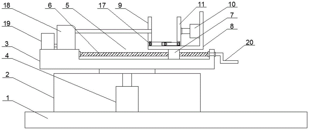
Fig. 1 is the overall structure schematic diagram of the lathe positioning mechanism of the present invention.
Fig. 2 is the schematic structural diagram of the first fixing plate and the stop block of the lathe positioning mechanism of the present invention.
Fig. 3 is the utility model relates to a lathe positioning mechanism's scale structure sketch map.
In the figure: 1. a lathe body; 2. a protective box; 3. a turntable; 4. a stepping motor; 5. a groove; 6. a screw rod; 7. silk blocks; 8. an L-shaped positioning table; 9. a first fixing plate; 10. an electric hydraulic push rod; 11. a second fixing plate; 12. a chute; 13. a stopper; 14. a telescopic sleeve; 15. a telescopic rod; 16. screwing down the screw; 17. fixing the screw rod; 18. a vacuum cleaner; 19. a dust storage box; 20. a rocker; 21. a graduated scale.
Detailed Description
In order to make the technical means, creation features, achievement purposes and functions of the present invention easy to understand, the present invention is further described below with reference to the following embodiments.
As shown in fig. 1-3, a lathe positioning mechanism comprises a lathe body 1, a protective box 2, a turntable 3 and a dust collector 18, wherein the protective box 2 is arranged at the top of the lathe body 1, the turntable 3 is mounted at the top of the protective box 2 through a bearing, a stepping motor 4 is arranged in the protective box 2, the stepping motor 4 is connected with the turntable 3 through a driving shaft, a groove 5 is arranged at the top of the turntable 3, a lead screw 6 is mounted in the groove 5 through a bearing, a corresponding lead screw block 7 is arranged at the periphery of the lead screw 6, an L-shaped positioning table 8 is arranged at the top of the lead screw block 7, a first fixing plate 9 is arranged at one side of the top of the L-shaped positioning table 8, an electric hydraulic push rod 10 is connected to the inner side of the L-shaped positioning table 8 through a bolt, the output end of the electric hydraulic push rod 10 is connected to a second fixing plate 11 through a bolt, a chute 12 is arranged in each of the first fixing plate 9 and the second fixing plate 11, one side of the first fixing plate 9 is provided with a stop block 13, a telescopic sleeve 14 is slidably connected in the sliding groove 12, one side of the telescopic sleeve 14 is connected with a telescopic rod 15 in a sleeved mode, and the surface of the telescopic sleeve 14 is connected with a tightening screw 16 through a reserved threaded hole in a threaded mode.
Wherein, one side of the first fixing plate 9 and one side of the second fixing plate 11 are both connected with a fixing screw 17 through a thread of a reserved threaded hole, and one end of the fixing screw 17 is positioned in the sliding groove 12.
In this embodiment, as shown in fig. 1-2, the telescopic sleeve 14 and the telescopic rod 15 are conveniently limited and fixed by the fixing screw 17, so that the stability of workpiece positioning is improved.
Wherein, a dust collector 18 is arranged on one side of the top of the rotary table 3, which is positioned on the groove 5, a dust storage box 19 is arranged on one side of the dust collector 18, the dust collecting end of the dust collector 18 is communicated with the first fixing plate 9 through a pipeline, and the dust outlet end of the dust collector 18 is communicated with the dust storage box 19 through a pipeline.
In the embodiment, as shown in fig. 1, the dust collector 18 and the dust storage box 19 facilitate collection of chips and dust generated during processing, so that an operator can clean the chips and dust conveniently, manpower consumption is greatly reduced, and the service life of the lathe can be prolonged.
Wherein, a rocker 20 is arranged on one side of the turntable 3 through a bearing, and the rocker 20 penetrates through the groove 5 and is connected with the screw rod 6.
In the embodiment, as shown in fig. 1, the rocker 20 is used for conveniently driving the screw rod 6 to rotate, so that the position of the L-shaped positioning table 8 is adjusted.
Wherein a scale 21 is arranged on the surface of the turntable 3.
In this embodiment, as shown in fig. 3, the position of the L-shaped positioning table 8 is conveniently adjusted according to the processing station by the scale 21, so that the accuracy of processing is improved.
It should be noted that, the utility model relates to a lathe positioning mechanism, in operation, firstly, the operator opens the stepping motor 4, the driving turntable 3 rotates to the outside, the positioning treatment is convenient for the operator, the potential safety hazard is reduced, the safety is improved, then the workpiece is placed in the inner side of the stop block 13, then the electric hydraulic push rod 10 is manually opened, the second fixing plate 11 is driven to horizontally move to contact with the workpiece, meanwhile, the telescopic rod 15 is pushed into the telescopic sleeve 14, then the screwing screw 16 is screwed to limit and fix the telescopic rod 15, then the operator screws the fixing screw 17 to the telescopic sleeve 14 and the telescopic rod 15 to contact with the workpiece, thereby the positioning treatment is carried out on the workpiece, finally, the rocker 20 is manually rotated, the position of the L-shaped positioning table 8 is adjusted according to the scale 21, the processing treatment is convenient, the structure is simple, the cost is low, when the processing treatment is carried out, can open dust catcher 18 by manual work, the produced piece of dust catcher 18 when will processing is inhaled with the dust and is carried and store in storing up dirt box 19, and the operating personnel of being convenient for carries out cleaning process, and the manpower that has significantly reduced consumes, can prolong the life of lathe moreover.
The basic principles and the main features of the invention and the advantages of the invention have been shown and described above. It will be understood by those skilled in the art that the present invention is not limited to the above embodiments, and that the foregoing embodiments and descriptions are provided only to illustrate the principles of the present invention without departing from the spirit and scope of the present invention. The scope of the invention is defined by the appended claims and equivalents thereof.