CN214815248U - Bar cutting machine - Google Patents
Bar cutting machine Download PDFInfo
- Publication number
- CN214815248U CN214815248U CN202121275554.4U CN202121275554U CN214815248U CN 214815248 U CN214815248 U CN 214815248U CN 202121275554 U CN202121275554 U CN 202121275554U CN 214815248 U CN214815248 U CN 214815248U
- Authority
- CN
- China
- Prior art keywords
- cutting
- bracket
- motor
- feeding
- plate
- Prior art date
- Legal status (The legal status is an assumption and is not a legal conclusion. Google has not performed a legal analysis and makes no representation as to the accuracy of the status listed.)
- Expired - Fee Related
Links
Images


Abstract
The utility model discloses a bar cutting machine, which comprises a frame, a cutting tool and a feeding tool, wherein the cutting tool and the feeding tool are respectively arranged on the upper surface of the frame, the cutting tool comprises a first motor, a first lead screw is fixedly connected with the output shaft end of the first motor, the lead screw is rotatably arranged on the upper surface of the frame, the two sides of the first lead screw are symmetrically arranged on the upper surface of the frame and are provided with a first linear guide rail, a cutting box is fixedly connected above the first linear guide rail, one side of the cutting box is provided with a cutting motor in a transmission way, the feeding tool comprises a feeding table and a second motor, the second motor is fixedly arranged on one side of a first groove, a second lead screw is rotatably arranged in the first groove, the two sides of the second lead screw are symmetrically arranged on the upper surface of the feeding table and are provided with a second linear guide rail, thereby ensuring that the bar can not generate displacement when feeding, thereby avoiding the phenomena of burrs, scratches and the like on the cutting surface of the metal round bar.
Description
Technical Field
The utility model belongs to the technical field of the bar cutting, concretely relates to bar cutting machine.
Background
In the process of machining parts, a round metal bar is often required to be cut into a plurality of sections and then machined, and the round metal bar cutting machine is a common machining device for round metal bars.
However, the existing metal round bar stock cutting machine mainly carries out hydraulic feeding and manual feeding, and has the functions of feeding bars to be cut in a hydraulic driving mode or a manual feeding mode and cutting the bars to a cutting and feeding device after feeding and length fixing are completed. The feeding device has the defects of low feeding precision, low automation degree, low efficiency, high labor cost and the like.
Meanwhile, in the prior art, in the cutting process of the metal round bar, as the bar clamping mechanism is fixed, when the bar is clamped, certain displacement is easily generated, so that the cutting is performed, the lower cutter position is inaccurate, burrs, scratches and other phenomena can occur on the cutting surface of the metal round bar, and the processing of the next procedure is not facilitated.
Therefore, the bar stock cutting machine is provided for solving the problems in the prior art, so that the working efficiency is improved, time and labor are saved, and the production labor cost of enterprises is reduced; meanwhile, the oblique cutting mechanism is arranged at the position of the bar clamping tool, so that when the bar is clamped, the stability of clamping is improved, the bar cannot displace when feeding is guaranteed, and therefore the phenomena of burrs, scratches and the like of a cutting surface of the metal round bar are avoided.
SUMMERY OF THE UTILITY MODEL
An object of the utility model is to provide a bar cutting machine, in order to solve and to propose among the above-mentioned background art not only material feeding unit have than lower pay-off precision, degree of automation is low, shortcomings such as inefficiency and cost of labor height, and among the metal round bar cutting process, because bar fixture is fixed, when the bar clamp is got, produce certain displacement easily, when leading to the cutting, the lower sword position is inaccurate, phenomenons such as burr and mar can appear in the cutting plane of metal round bar, be unfavorable for the problem of the processing of process on next step.
In order to achieve the above purpose, the utility model adopts the following technical scheme:
a bar cutting machine comprises a rack, a cutting tool and a feeding tool, wherein the cutting tool and the feeding tool are respectively arranged on the upper surface of the rack, the cutting tool comprises a first motor, an output shaft end of the first motor is fixedly connected with a first lead screw, the lead screw is rotatably arranged on the upper surface of the rack, first linear guide rails are symmetrically arranged on the upper surface of the rack on two sides of the first lead screw, a cutting box is fixedly connected above the first linear guide rails, and the cutting motor is installed on one side of the cutting box in a transmission manner;
the feeding tool comprises a feeding table and a second motor, wherein a first groove is formed in the feeding table, the second motor is fixedly installed on one side of the first groove, a second lead screw is rotatably installed in the first groove, second linear guide rails are symmetrically installed on the upper surface of the feeding table on two sides of the second lead screw, and clamping assemblies are fixedly installed on the two groups of second linear guide rails;
the clamping assembly comprises a base, a clamping tool is arranged above the base, a first hydraulic cylinder is fixedly mounted on one side of the base, and a double-lug support is fixedly mounted on an output shaft end of the first hydraulic cylinder;
the clamping tool comprises a bracket, wherein an ear plate is connected with one side of the bracket in a pin joint mode, the ear plate is fixedly connected with a double-lug support in a pin joint mode, a first clamping plate is fixedly installed on one side, away from the ear plate, of the bracket, a second clamping plate is slidably installed on one side, away from the first clamping plate, of the bracket, a second hydraulic cylinder is fixedly installed on one side of the second clamping plate, the second hydraulic cylinder is fixedly installed on the upper surface of the bracket, a cushion block is arranged between the base and the bracket, and a slope is formed in the contact surface of the cushion block and the bottom of the bracket;
the automatic feeding machine is characterized in that a positioning tool is fixedly mounted between the cutting tool and the feeding tool on one side of the rack, the positioning tool comprises a base, and a positioning table is fixedly mounted on the top of the base.
Preferably, the frame is the setting of L type structure, the frame upper surface is located cutting frock one side fixed mounting and connects the silo, connect silo bottom one side symmetry to be provided with the support frame, the connect silo bottom is located frame upper surface fixed mounting and has the otter board, be provided with automatically controlled cabinet in the frame.
Preferably, a machine head is fixedly mounted on one side of the cutting box, the machine head is rotatably mounted on the cutting knife wheel, and a rotating shaft fixedly mounted in the cutting knife wheel is in transmission connection with an output shaft end of the cutting motor through a gear pair.
Preferably, a vertical plate is fixedly mounted on one side, close to the second motor, of the feeding table, and a carrier roller is rotatably mounted at the top of the vertical plate.
Preferably, the bracket is internally provided with positioning holes symmetrically formed in two sides of the second hydraulic cylinder, linear bearings are fixedly mounted in the positioning holes, guide rods are slidably mounted in the linear bearings, and one ends of the guide rods are fixedly connected with the second clamping plate.
Preferably, the top of the bracket is fixedly provided with a protection plate above the first clamping plate and the second clamping plate.
Preferably, the upper surface of the rack is provided with supporting plates at two ends of the first screw rod, the first groove is provided with supporting plates at two ends of the second screw rod, and the two ends of the first screw rod and the two ends of the second screw rod are respectively rotatably arranged in the two adjacent groups of supporting plates through bearings.
Preferably, the locating plate is fixedly mounted at the top of the machine head, a locating strip is fixedly mounted on one side of the locating plate, and a proximity switch is fixedly mounted at one end of the locating strip.
Preferably, a second groove is formed in the base and located right below the bracket, and a supporting rod is rotatably mounted in the second groove.
The utility model discloses a technological effect and advantage: the utility model provides a pair of bar cutting machine compares with prior art, has following advantage:
1. the feeding mechanism and the cutting mechanism are arranged to act together to convey the bar stock, the bar stock is conveyed into the cutting mechanism through feeding, and the cutting wheel in the machine head is used for cutting the bar stock, so that the working efficiency of the cutting machine is improved, the time and the labor are saved, and the production and labor cost of enterprises is reduced;
2. set up at bar centre gripping frock department and cut oblique mechanism, when carrying out the centre gripping to the bar, improve the stability of centre gripping, the bar can not produce the displacement when guaranteeing the feed to avoid phenomenons such as burr and mar to appear in the cutting plane of metal round bar.
Drawings
Fig. 1 is a schematic view of a main view direction three-dimensional structure of the present invention;
fig. 2 is a schematic perspective view of the cutting tool of the present invention;
fig. 3 is a schematic side view of the cutting tool of the present invention;
fig. 4 is a schematic perspective view of the feeding tool of the present invention;
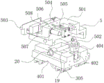
fig. 5 is a schematic perspective view of the clamping assembly of the present invention;
FIG. 6 is a schematic side view of the clamping assembly of the present invention;
fig. 7 is a schematic view of a rear-view perspective structure of the present invention;
fig. 8 is a schematic top view of the present invention.
In the figure: 1. a frame; 2. cutting a tool; 201. a first motor; 202. a first lead screw; 203. a first linear guide rail; 204. cutting the box; 205. cutting the motor; 3. feeding tooling; 301. a feeding table; 302. a second motor; 303. a first groove; 304. a second lead screw; 305. a second linear guide; 306. a vertical plate; 307. a carrier roller; 4. a clamping assembly; 401. a base; 402. a first hydraulic cylinder; 404. a double-lug support; 5. clamping a tool; 501. a bracket; 502. an ear plate; 503. a first splint; 504. a second splint; 505. a second hydraulic cylinder; 506. positioning holes; 507. a linear bearing; 508. a guide bar; 509. a protection plate; 6. cushion blocks; 7. a slope; 8. positioning a tool; 801. a base; 9. a positioning table; 10. a material receiving groove; 11. a support frame; 12. a screen plate; 13. an electric control cabinet; 14. a machine head; 15. cutting the cutter wheel; 16. positioning a plate; 17. a positioning bar; 18. a proximity switch; 19. a second groove; 20. a support bar; 21. and a support plate.
Detailed Description
The technical solutions in the embodiments of the present invention will be described clearly and completely with reference to the accompanying drawings in the embodiments of the present invention, and it is obvious that the described embodiments are only some embodiments of the present invention, not all embodiments. The specific embodiments described herein are merely illustrative of the invention and are not intended to be limiting of the invention. Based on the embodiments in the present invention, all other embodiments obtained by a person skilled in the art without creative work belong to the protection scope of the present invention.
The utility model provides a bar stock cutting machine as shown in figures 1-8, which comprises a frame 1, a cutting tool 2 and a feeding tool 3, wherein the cutting tool 2 and the feeding tool 3 are respectively arranged on the upper surface of the frame 1, the cutting tool 2 comprises a first motor 201, a first screw rod 202 is fixedly connected with the output shaft end of the first motor 201, the first screw rod 202 is rotatably arranged on the upper surface of the frame 1, the two sides of the first screw rod 202 are symmetrically provided with a first linear guide rail 203 on the upper surface of the frame 1, a cutting box 204 is fixedly connected above the first linear guide rail 203, a cutting motor 205 is arranged on one side of the cutting box 204 in a transmission way, a machine head 14 is fixedly arranged on one side of the cutting box 204, the machine head 14 is rotatably arranged on a cutting knife wheel 15, a rotating shaft fixedly arranged in the cutting knife wheel 15 is connected with the output of the cutting motor 205 through a gear pair transmission way, the top of the machine head 14 is fixedly provided with a positioning plate 16, one side of the positioning plate 16 is fixedly provided with a positioning strip 17, and one end of the positioning strip 17 is fixedly provided with a proximity switch 18.
1 one side of frame is located fixed mounting between cutting frock 2 and the feeding frock 3 and has location frock 8, location frock 8 includes base 801, base 801 top fixed mounting has location platform 9, frame 1 is the setting of L type structure, 1 upper surface of frame is located cutting frock 2 one side fixed mounting and connects silo 10, it is provided with support frame 11 to connect silo 10 bottom one side symmetry, it has otter board 12 to connect silo 10 bottom to be located 1 upper surface fixed mounting in frame, be provided with automatically controlled cabinet 13 in the frame 1.
The feeding tool 3 comprises a feeding table 301 and a second motor 302, a first groove 303 is formed in the feeding table 301, the second motor 302 is fixedly installed on one side of the first groove 303, a second lead screw 304 is rotatably installed in the first groove 303, second linear guide rails 305 are symmetrically installed on the upper surface of the feeding table 301 on two sides of the second lead screw 304, a vertical plate 306 is fixedly installed on one side, close to one side of the second motor 302, of the feeding table 301, and a carrier roller 307 is rotatably installed at the top of the vertical plate 306.
Two sets of fixed mounting has centre gripping subassembly 4 on the second linear guide 305, centre gripping subassembly 4 includes base 401, base 401 top is provided with centre gripping frock 5, base 401 one side fixed mounting has first pneumatic cylinder 402, the output shaft fixed mounting of first pneumatic cylinder 402 has ears support 404, be located in the base 401 under the bracket 501 and seted up second recess 19, bracing piece 20 is installed in the rotation of second recess 19.
The upper surface of the machine frame 1 is provided with support plates 21 at two ends of the first screw rod 202, the first groove 303 is provided with support plates 21 at two ends of the second screw rod 304, and the two ends of the first screw rod 202 and the second screw rod 304 are rotatably arranged in two adjacent groups of support plates 21 through bearings respectively.
The clamping tool 5 comprises a bracket 501, an ear plate 502 is pinned on one side of the bracket 501, the ear plate 502 is fixed with the double ear support 404 by a pin joint, a first clamping plate 503 is fixedly arranged on one side of the bracket 501 far away from the ear plate 502, a second clamping plate 504 is slidably mounted on the side of the bracket 501 away from the first clamping plate 503, a second hydraulic cylinder 505 is fixedly installed on one side of the second clamping plate 504, the second hydraulic cylinder 505 is fixedly installed on the upper surface of the bracket 501, a cushion block 6 is arranged between the base 401 and the bracket 501, a slope 7 is arranged on the contact surface of the cushion block 6 and the bottom of the bracket 501, positioning holes 506 are symmetrically formed in the bracket 501 at two sides of the second hydraulic cylinder 505, linear bearings 507 are fixedly arranged in the positioning holes 506, guide rods 508 are arranged in the linear bearings 507 in a sliding manner, one end of the guide rod 508 is fixedly connected with the second clamping plate 504, and a protection plate 509 is fixedly arranged on the top of the bracket 501 above the first clamping plate 503 and the second clamping plate 504.
The working principle is as follows: the feeding tool 3 and the cutting tool 2 are arranged to act together to convey the bar, the bar is clamped through the clamping component 4, the second motor 302 is started to convey the clamping component 4 into the positioning table 9, the first motor 201 is started to drive the cutting tool 2 to feed the bar, and after the cutting position is limited by the proximity switch 18, the cutting motor 205 is started to drive the cutting knife wheel 15 to cut the bar, so that the working efficiency is improved, time and labor are saved, and the production and labor cost of enterprises is reduced;
set up the cushion 6 that has slope 7 in bar clamping component 4 department, utilize first pneumatic cylinder 402 drive bracket 501, promote bar slope back, restart second pneumatic cylinder 505 drives second splint 504 and supports the first splint 503 of bar workbin and draw close, when carrying out the centre gripping to the bar, improve the stability of centre gripping, the bar can not produce the displacement when guaranteeing the feed, thereby phenomenon such as burr and mar appear in the cutting plane of avoiding metal round bar.
Finally, it should be noted that: although the present invention has been described in detail with reference to the foregoing embodiments, it will be apparent to those skilled in the art that modifications and variations can be made in the embodiments or in part of the technical features of the embodiments without departing from the spirit and the scope of the invention.
Claims (9)
1. The utility model provides a bar stock cutting machine, includes frame (1), cutting frock (2) and feeding frock (3), its characterized in that: the cutting tool (2) and the feeding tool (3) are respectively arranged on the upper surface of the rack (1), the cutting tool (2) comprises a first motor (201), an output shaft end of the first motor (201) is fixedly connected with a first lead screw (202), the first lead screw (202) is rotatably installed on the upper surface of the rack (1), first linear guide rails (203) are symmetrically arranged on the upper surface of the rack (1) on two sides of the first lead screw (202), a cutting box (204) is fixedly connected above the first linear guide rails (203), and a cutting motor (205) is installed on one side of the cutting box (204) in a transmission mode;
the feeding tool (3) comprises a feeding table (301) and a second motor (302), a first groove (303) is formed in the feeding table (301), the second motor (302) is fixedly installed on one side of the first groove (303), a second lead screw (304) is rotatably installed in the first groove (303), second linear guide rails (305) are symmetrically installed on the upper surface of the feeding table (301) on two sides of the second lead screw (304), and clamping assemblies (4) are fixedly installed on the two groups of second linear guide rails (305);
the clamping assembly (4) comprises a base (401), a clamping tool (5) is arranged above the base (401), a first hydraulic cylinder (402) is fixedly installed on one side of the base (401), and a double-lug support (404) is fixedly installed on an output shaft end of the first hydraulic cylinder (402);
the clamping tool (5) comprises a bracket (501), an ear plate (502) is in pin joint with one side of the bracket (501), the ear plate (502) is in pin joint with a double-ear support (404) for fixation, a first clamping plate (503) is fixedly installed on one side, away from the ear plate (502), of the bracket (501), a second clamping plate (504) is installed on one side, away from the first clamping plate (503), of the bracket (501) in a sliding mode, a second hydraulic cylinder (505) is fixedly installed on one side of the second clamping plate (504), the second hydraulic cylinder (505) is fixedly installed on the upper surface of the bracket (501), a cushion block (6) is arranged between the base (401) and the bracket (501), and a slope (7) is formed on one side, in contact with the bottom of the bracket (501), of the cushion block (6);
frame (1) one side is located fixed mounting between cutting frock (2) and feeding frock (3) and has location frock (8), location frock (8) include base (801), base (801) top fixed mounting has location platform (9).
2. The bar cutter according to claim 1, characterized in that: frame (1) is the setting of L type structure, frame (1) upper surface is located cutting frock (2) one side fixed mounting and connects silo (10), it is provided with support frame (11) to connect silo (10) bottom one side symmetry, it has otter board (12) to connect silo (10) bottom to be located frame (1) upper surface fixed mounting, be provided with automatically controlled cabinet (13) in frame (1).
3. The bar cutter according to claim 1, characterized in that: a machine head (14) is fixedly mounted on one side of the cutting box (204), the machine head (14) is rotatably mounted in the cutting knife wheel (15), and a rotating shaft fixedly mounted in the cutting knife wheel (15) is in transmission connection with an output shaft end of the cutting motor (205) through a gear pair.
4. The bar cutter according to claim 1, characterized in that: a vertical plate (306) is fixedly mounted on one side, close to the second motor (302), of the feeding table (301), and a carrier roller (307) is rotatably mounted at the top of the vertical plate (306).
5. The bar cutter according to claim 1, characterized in that: locating holes (506) are symmetrically formed in two sides of a second hydraulic cylinder (505) in the bracket (501), linear bearings (507) are fixedly mounted in the locating holes (506), guide rods (508) are slidably mounted in the linear bearings (507), and one ends of the guide rods (508) are fixedly connected with a second clamping plate (504).
6. The bar cutter according to claim 1, characterized in that: and a protection plate (509) is fixedly arranged on the top of the bracket (501) above the first clamping plate (503) and the second clamping plate (504).
7. The bar cutter according to claim 1, characterized in that: the support plate (21) is fixedly mounted at two ends of the first screw rod (202) on the upper surface of the rack (1), the support plates (21) are fixedly mounted at two ends of the second screw rod (304) in the first groove (303), and the two ends of the first screw rod (202) and the second screw rod (304) are rotatably mounted in two adjacent groups of support plates (21) through bearings respectively.
8. A bar cutter according to claim 3, characterized in that: the locating plate (16) is fixedly mounted at the top of the machine head (14), a locating strip (17) is fixedly mounted on one side of the locating plate (16), and a proximity switch (18) is fixedly mounted at one end of the locating strip (17).
9. The bar cutter according to claim 1, characterized in that: a second groove (19) is formed in the base (401) and located under the bracket (501), and a supporting rod (20) is rotatably mounted in the second groove (19).
Priority Applications (1)
| Application Number | Priority Date | Filing Date | Title |
|---|---|---|---|
| CN202121275554.4U CN214815248U (en) | 2021-06-08 | 2021-06-08 | Bar cutting machine |
Applications Claiming Priority (1)
| Application Number | Priority Date | Filing Date | Title |
|---|---|---|---|
| CN202121275554.4U CN214815248U (en) | 2021-06-08 | 2021-06-08 | Bar cutting machine |
Publications (1)
| Publication Number | Publication Date |
|---|---|
| CN214815248U true CN214815248U (en) | 2021-11-23 |
Family
ID=78804225
Family Applications (1)
| Application Number | Title | Priority Date | Filing Date |
|---|---|---|---|
| CN202121275554.4U Expired - Fee Related CN214815248U (en) | 2021-06-08 | 2021-06-08 | Bar cutting machine |
Country Status (1)
| Country | Link |
|---|---|
| CN (1) | CN214815248U (en) |
-
2021
- 2021-06-08 CN CN202121275554.4U patent/CN214815248U/en not_active Expired - Fee Related
Similar Documents
| Publication | Publication Date | Title |
|---|---|---|
| CN213646116U (en) | Novel section bar saw cut machining center | |
| CN213729679U (en) | Two-chuck movable pipe cutting machine | |
| CN208099626U (en) | A kind of multi-functional tube sheet one optical-fiber laser cutting machine | |
| CN214815248U (en) | Bar cutting machine | |
| CN113210707A (en) | Bar cutting machine | |
| CN213380233U (en) | Portable long material chamfering device | |
| CN211804072U (en) | Vertical sheet metal keyway planer | |
| CN215150683U (en) | Roller adjusting structure of single-wire or multi-wire composite cutting machine | |
| CN212042441U (en) | Automatic cutting equipment suitable for processing industry | |
| CN214134964U (en) | Clamping device of numerical control machine tool | |
| CN213918447U (en) | Wedge cushion block arc angle back chipping device | |
| CN215356532U (en) | Automatic groove processing device | |
| CN217799334U (en) | High-efficient cutting device of steel ingot blank | |
| CN220839169U (en) | Vertical guiding gutter shearing mechanism of photovoltaic board support | |
| CN111231142A (en) | Loop wire cutting machine | |
| CN211966741U (en) | Horizontal section bar processing machine tool | |
| CN219483980U (en) | Efficient stamping equipment for metal art window decoration production | |
| CN220805701U (en) | Triaxial tailing pulling mechanism of circular sawing machine | |
| CN218311595U (en) | XY axle welding machine | |
| CN217702528U (en) | Five-axis horizontal type plate turnover machining center | |
| CN217596498U (en) | Rapid adjusting clamp | |
| CN117620458A (en) | Laser pipe cutting machine | |
| CN216990029U (en) | Laser scanning section bar terminal surface reciprocating milling cuts numerical control end surface milling machine | |
| CN210649285U (en) | Welding table for welding bus bar and battery string | |
| CN217628134U (en) | Positioning and cutting device for machining laminated glass |
Legal Events
| Date | Code | Title | Description |
|---|---|---|---|
| GR01 | Patent grant | ||
| GR01 | Patent grant | ||
| CF01 | Termination of patent right due to non-payment of annual fee | ||
| CF01 | Termination of patent right due to non-payment of annual fee |
Granted publication date: 20211123 |