CN214737765U - Prefabricated assembly component erecting equipment capable of walking by means of front and rear inverted rails - Google Patents
Prefabricated assembly component erecting equipment capable of walking by means of front and rear inverted rails Download PDFInfo
- Publication number
- CN214737765U CN214737765U CN202120588071.3U CN202120588071U CN214737765U CN 214737765 U CN214737765 U CN 214737765U CN 202120588071 U CN202120588071 U CN 202120588071U CN 214737765 U CN214737765 U CN 214737765U
- Authority
- CN
- China
- Prior art keywords
- main beam
- rail
- walking
- electric hoist
- pair
- Prior art date
- Legal status (The legal status is an assumption and is not a legal conclusion. Google has not performed a legal analysis and makes no representation as to the accuracy of the status listed.)
- Active
Links
Images


Abstract
The utility model discloses a prefabricated assembly component that falls the rail around dependence walks capable erects equipment, include: the upper structure comprises a transversely arranged main beam, an electric hoist rail is longitudinally arranged on the main beam and is arranged to transversely move along the main beam, a pair of electric hoists are arranged on the electric hoist rail in a sliding fit mode and are respectively positioned on two sides of the main beam, and a crown block is further arranged on the main beam and is used for hoisting prefabricated parts through a crown block hanger; the lower structure comprises a pair of supporting legs arranged at intervals in the longitudinal direction, the upper ends of the pair of supporting legs are fixedly supported on the main beam, the lower end of the main beam is provided with a walking wheel which is in sliding fit in a walking track, and the walking track is provided with a plurality of sections and is sequentially and closely laid on the wharf along the longitudinal direction. The utility model has the advantages of improve the efficiency of construction, reduce the influence to all ring edge borders, reduce artifical the input, reduce the construction risk, guarantee construction quality.
Description
Technical Field
The utility model relates to a construction equipment technical field. More specifically, the utility model relates to rely on the front and back to fall the rail and walk prefabricated assembly component of line and erect equipment.
Background
The prefabrication and assembly has become a trend, and the prefabrication and assembly not only gradually starts to be applied in the field of bridge construction, but also gradually replaces the cast-in-place in the construction of wharfs. The bridge mostly is along the longitudinal bridge to the construction, adopts the bridging machine to stride along the longitudinal bridge to the construction gradually then can solve prefabricated component's the problem of erectting well, but the pier is different from the bridge, and plane prefabricated component is more to can supply the less even not in space of bridging machine station position.
Consequently in order to solve the problem of erectting of pier prefabricated component, improve the efficiency of construction, reduce the influence to the surrounding environment, reduce artifical input, reduce the construction risk, guarantee construction quality, need urgently one kind can satisfy the large-scale integration construction equipment of above requirement.
SUMMERY OF THE UTILITY MODEL
An object of the utility model is to provide a prefabricated assembly component that walks capable is laid to rail around relying on erects and equips, has the improvement efficiency of construction, reduces the influence to all ring edge borders, reduces artifical the input, reduces the construction risk, guarantees advantages such as construction quality.
In order to achieve these objects and other advantages in accordance with the purpose of the invention, a prefabricated component erection equipment that runs by leaning on a front and a rear rail is provided, comprising:
the hoisting device comprises a main beam, an electric hoist rail, a crane and a hoisting crane, wherein the main beam is transversely arranged, the electric hoist rail is longitudinally arranged on the main beam and is arranged to transversely move along the main beam, a pair of electric hoists are arranged on the electric hoist rail in a sliding fit manner and are respectively positioned on two sides of the main beam, the electric hoists have a hoisting function, and the main beam is also provided with the crane and is used for hoisting the prefabricated part through a crane hoist;
the lower structure comprises a pair of supporting legs arranged at intervals in the longitudinal direction, the upper ends of the pair of supporting legs are fixedly supported on the main beam, the lower end of the main beam is provided with a walking wheel which is in sliding fit in a walking track, and the walking track is provided with a plurality of sections and is sequentially and closely laid on the wharf along the longitudinal direction.
Preferably, the main beam is formed by combining two box-type beams side by side along the longitudinal direction.
Preferably, the crane sling is a 360-degree full-rotation sling.
Preferably, the traveling rail is provided with 3 sections.
Preferably, two groups of substructures are arranged below the main beam and are respectively positioned on two different wharfs.
Preferably, a telescopic oil cylinder is arranged on the main beam and used for driving the electric hoist track to transversely move along the main beam.
The utility model discloses at least, include following beneficial effect:
1. the utility model discloses an equip and through equipping the walking track that the distance was only laid to indulge that the hole mode was moved that proposes, need not the full line and lay, reduce construction cost.
2. The utility model discloses reduced the artifical input in scene, it is little to the environmental impact, improved the efficiency of construction, had good economic benefits.
Additional advantages, objects, and features of the invention will be set forth in part in the description which follows and in part will become apparent to those having ordinary skill in the art upon examination of the following or may be learned from practice of the invention.
Drawings
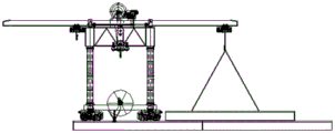
Fig. 1 is a schematic view of the lateral structure of the present invention;
FIG. 2 is a schematic longitudinal structure of the present invention;
FIG. 3 is a schematic structural diagram of the first step of the equipment construction method of the present invention;
FIG. 4 is a schematic structural view of step two of the equipment construction method of the present invention;
FIG. 5 is a schematic structural view of a third step of the equipment construction method of the present invention;
FIG. 6 is a schematic structural view of the fourth step of the equipment construction method of the present invention;
FIG. 7 is a schematic structural view of the fifth step of the equipment construction method of the present invention;
FIG. 8 is a schematic structural view of a sixth step of the equipment construction method of the present invention;
FIG. 9 is a schematic structural view of a seventh step of the equipment construction method of the present invention;
fig. 10 is a schematic structural diagram of step eight of the equipment construction method of the present invention.
Description of reference numerals:
1. girder, 2, overhead traveling crane, 3, landing leg, 4, electric block track, 5, electric block, 6, walking wheel, 7, walking track, 8, hoist, 9, prefabricated component, 10, pier.
Detailed Description
The present invention is further described in detail below with reference to the drawings so that those skilled in the art can implement the invention with reference to the description.
It is to be noted that the experimental methods described in the following embodiments are all conventional methods unless otherwise specified, and the reagents and materials, if not otherwise specified, are commercially available; in the description of the present invention, the terms "lateral", "longitudinal", "up", "down", "front", "back", "left", "right", "vertical", "horizontal", "top", "bottom", "inner", "outer", etc. indicate orientations or positional relationships based on the orientations or positional relationships shown in the drawings, and are only for convenience of description and simplicity of description, and do not indicate or imply that the device or element referred to must have a particular orientation, be constructed and operated in a particular orientation, and therefore, should not be construed as limiting the present invention.
As shown in fig. 1 and 2, the utility model provides a prefabricated component that walks by leaning on back and forth rail turnover erects and equips, include:
the hoisting device comprises an upper structure and a lower structure, wherein the upper structure comprises a main beam 1 which is transversely arranged, an electric hoist rail 4 is longitudinally arranged on the main beam 1 and is arranged to transversely move along the main beam 1, a pair of electric hoists 5 are arranged on the electric hoist rail 4 in a sliding fit mode and are respectively positioned on two sides of the main beam 1, the electric hoists 5 have a hoisting function, and a crown block 2 is further arranged on the main beam 1 and is used for hoisting a prefabricated part 9 through a crown block hanger 8;
the lower structure comprises a pair of supporting legs 3 arranged at intervals in the longitudinal direction, the upper ends of the pair of supporting legs 3 are fixedly supported on the main beam 1, the lower end of the main beam is provided with a walking wheel 6 which is in sliding fit with the walking track 7, and the walking track 7 is provided with a plurality of sections and is sequentially and closely laid on the wharf 10 along the longitudinal direction.
In the above technical scheme, the girder 1 and the pair of supporting legs 3 form a portal structure, the longitudinal movement of the girder 1 is realized through the walking of the supporting legs 3, and a traditional bridge girder erection machine is not used, so that the crane 2 on the girder 1 can hoist and erect the prefabricated part 9 through the lifting appliance 8. The arrangement of the electric hoist track 4, the electric hoist 5 and the multi-section walking track 7 realizes continuous longitudinal movement of the main beam 1 and the supporting legs 3 through the simple multi-section walking track 7 by the construction method provided by the application, the walking track 7 needs to be laid on the whole line, the defect that the occupation space of the wharf 10 is small or even none is overcome, and the erection problem of the prefabricated part 9 of the wharf 10 is solved. The electric hoist rail 4 is a common sliding rail, and the electric hoist 5 is fitted in the electric hoist rail 4 to slide along the length direction thereof, i.e., the longitudinal direction of the present application. The overhead traveling crane 2 on the main beam 1 can also be connected to the main beam 1 by adopting the conventional sliding way, so that the overhead traveling crane 2 can be moved to a proper position according to the requirement.
In another technical scheme, the main beam 1 is formed by combining two box beams side by side along the longitudinal direction, the two box beams are fixedly connected and widen the main beam 1, and the crown block 2 is positioned at the center of the main beam 1.
In another technical scheme, the crane sling 8 is a 360-degree full-rotation sling, and a conventional full-rotation sling is adopted, so that full rotation can be realized, on one hand, steering of the prefabricated part 9 can be realized, and on the other hand, longitudinal movement of the walking track 7 can be assisted.
In another technical scheme, the walking track 7 is provided with 3 sections.
In another technical solution, two sets of substructures are arranged under the main beam 1, which are respectively located on two different docks 10.
In another kind of technical scheme, be provided with flexible hydro-cylinder on the girder 1, it is used for the drive electric block track 4 is followed girder 1 lateral shifting, electric block track 4 generally is for following girder 1 bilateral symmetry setting.
In the orientation shown in fig. 3 to 10, the left side is referred to as the front and the right side is referred to as the rear.
As shown in fig. 3 to 10, the method for constructing by using the prefabricated assembly component erecting equipment which runs by means of front and rear inverted rails of the utility model specifically comprises the following steps:
the method comprises the following steps: paving a walking rail 7 on the wharf 10 and installing and erecting equipment, wherein the whole equipment longitudinally moves on the walking rail 7 by virtue of walking wheels 6 at the lower ends of supporting legs 3, at the moment, an electric hoist rail 4 and the walking rail 7 are in the same vertical plane, a main beam 1 is positioned right above the middle walking rail 7, and the electric hoist 5 in front lifts the walking rail 7 in front to drive the electric hoist rail 4 to transversely move to a position which is not in the same vertical plane as the walking rail 7;
step two: the front electric hoist 5 lifts the front traveling rail 7 to move backwards along the electric hoist rail 4 until the rear side of the front traveling rail 7 is positioned in the middle of the main beam 1;
step three: the whole device moves to a rear walking track 7 by virtue of the walking wheels 6 at the lower ends of the supporting legs 3;
step four: the front electric hoist 5 lowers the front traveling rail 7, and lifts the front traveling rail 7 by a crane 2 hanger 8 on the main beam 1 and rotates to a position where the front traveling rail 7 can be lifted by the rear electric hoist 5;
step five: the rear electric hoist 5 moves forwards along the electric hoist track 4 and lifts the front walking track 7, the whole device moves to the middle walking track 7 by virtue of the walking wheels 6 at the lower ends of the supporting legs 3, and then the rear electric hoist 5 moves backwards to the rear side of the electric hoist track 4;
step six: the rear electric hoist 5 lifts the front walking rail 7 and drives the electric hoist rail 4 to transversely move to be in the same vertical plane with the walking rail 7;
step seven: the whole device moves to a rear walking track 7 by virtue of the walking wheels 6 at the lower ends of the supporting legs 3, and the walking track 7 in front of the electric hoist 5 lifted at the rear is just behind the rear walking track 7;
step eight: the front running rail 7 is lowered to become a new rear running rail 7.
Step nine: repeating the steps until the walking track 7 is longitudinally moved to the right position, namely the whole equipment is longitudinally moved to the right position;
step ten: after the crane 2 is moved to the position, the crane lifts the prefabricated part 9 to the set position by the lifting appliance 8 to erect the wharf 10.
While the embodiments of the invention have been described above, it is not intended to be limited to the details shown, or described, but rather to cover all modifications, which would come within the scope of the appended claims, and all changes which come within the meaning and range of equivalency of the art are therefore intended to be embraced therein.
Claims (6)
1. The prefabricated component that walks to lean on back rail is erect and is equipped, its characterized in that includes:
the hoisting device comprises a main beam, an electric hoist rail, a crane and a hoisting crane, wherein the main beam is transversely arranged, the electric hoist rail is longitudinally arranged on the main beam and is arranged to transversely move along the main beam, a pair of electric hoists are arranged on the electric hoist rail in a sliding fit manner and are respectively positioned on two sides of the main beam, the electric hoists have a hoisting function, and the main beam is also provided with the crane and is used for hoisting the prefabricated part through a crane hoist;
the lower structure comprises a pair of supporting legs arranged at intervals in the longitudinal direction, the upper ends of the pair of supporting legs are fixedly supported on the main beam, the lower end of the main beam is provided with a walking wheel which is in sliding fit in a walking track, and the walking track is provided with a plurality of sections and is sequentially and closely laid on the wharf along the longitudinal direction.
2. Prefabricated construction assembly equipment for running on front and rear inverted rails according to claim 1, wherein the main beam is formed by combining two box-type beams side by side in the longitudinal direction.
3. Prefabricated construction assembly equipment depending on front and rear inverted rail running according to claim 1, wherein the overhead travelling crane spreader is a 360 ° full swing spreader.
4. Prefabricated construction equipment for erecting running members by means of front and rear inverted rails according to claim 1, characterized in that said running rails are provided with 3 sections.
5. Prefabricated construction assembly equipment depending on front and rear inverted rail running according to claim 1, characterized in that two sets of substructures are arranged under the main beam, which are respectively located on two different quays.
6. The prefabricated component erection equipment running on front and rear inverted rails according to claim 1, wherein a telescopic cylinder is arranged on the main beam and used for driving the electric hoist rail to move transversely along the main beam.
Priority Applications (1)
| Application Number | Priority Date | Filing Date | Title |
|---|---|---|---|
| CN202120588071.3U CN214737765U (en) | 2021-03-23 | 2021-03-23 | Prefabricated assembly component erecting equipment capable of walking by means of front and rear inverted rails |
Applications Claiming Priority (1)
| Application Number | Priority Date | Filing Date | Title |
|---|---|---|---|
| CN202120588071.3U CN214737765U (en) | 2021-03-23 | 2021-03-23 | Prefabricated assembly component erecting equipment capable of walking by means of front and rear inverted rails |
Publications (1)
| Publication Number | Publication Date |
|---|---|
| CN214737765U true CN214737765U (en) | 2021-11-16 |
Family
ID=78596338
Family Applications (1)
| Application Number | Title | Priority Date | Filing Date |
|---|---|---|---|
| CN202120588071.3U Active CN214737765U (en) | 2021-03-23 | 2021-03-23 | Prefabricated assembly component erecting equipment capable of walking by means of front and rear inverted rails |
Country Status (1)
| Country | Link |
|---|---|
| CN (1) | CN214737765U (en) |
-
2021
- 2021-03-23 CN CN202120588071.3U patent/CN214737765U/en active Active
Similar Documents
| Publication | Publication Date | Title |
|---|---|---|
| CN207498755U (en) | A kind of traveling trolley adjusted with horizontal extension and vertical supporting | |
| CN211848975U (en) | Block mounting device for ultra-wide steel box girder of cable-stayed bridge | |
| CN108677742A (en) | The moving cantilever type Bridge Erector of full precast pier, cushion cap and beam body prefabricated construction | |
| CN110804958B (en) | Whole hole beam frame changing method | |
| CN110777681A (en) | Whole hole roof beam trades a equipment | |
| CN105421239B (en) | Hoisting method for large-span highway-railway dual-purpose steel truss girder bridge deck slab | |
| CN108130862B (en) | Tunnel passing beam vehicle | |
| CN107311047B (en) | The steel box-girder lift structure and method for improving of large span bondbeam | |
| CN214737765U (en) | Prefabricated assembly component erecting equipment capable of walking by means of front and rear inverted rails | |
| CN110804960B (en) | Whole hole beam frame replacing method | |
| CN113106918A (en) | Prefabricated assembly component erecting equipment capable of walking by means of front and rear inverted rails and construction method | |
| CN211256692U (en) | Transport beam structure of newly-built upper bridge on current bridge | |
| CN110065783B (en) | Track crossing type transport vehicle | |
| CN107604828A (en) | The Bridge Erector of double-T shaped beam bridge | |
| CN214423296U (en) | Special equipment for erecting prefabricated parts | |
| CN110747757A (en) | Whole hole beam replacement frame equipment | |
| CN207904776U (en) | Cross tunnel beam car | |
| CN107401124A (en) | The Bridge Erector of T-shaped beam bridge | |
| CN208792167U (en) | The moving cantilever type Bridge Erector of full precast pier, cushion cap and beam body prefabricated construction | |
| CN111648173A (en) | Track panel laying machine | |
| CN207760711U (en) | A kind of crawler type inverted arch trestle | |
| CN208232055U (en) | The whole pre- bundle mould of the movable prefabricated T beam steel that can be shared | |
| CN202429915U (en) | Large-tonnage lifting hook overhead crane | |
| CN112554068A (en) | Combined construction equipment and construction method for fully-prefabricated bridge pier and bridge | |
| CN104929056A (en) | Spherical surface rail hydraulic transmission and control bridge erecting machine, bridge erecting system and bridge erecting method |
Legal Events
| Date | Code | Title | Description |
|---|---|---|---|
| GR01 | Patent grant | ||
| GR01 | Patent grant |