CN214270151U - Bridge type electric lifting platform - Google Patents
Bridge type electric lifting platform Download PDFInfo
- Publication number
- CN214270151U CN214270151U CN202023299303.8U CN202023299303U CN214270151U CN 214270151 U CN214270151 U CN 214270151U CN 202023299303 U CN202023299303 U CN 202023299303U CN 214270151 U CN214270151 U CN 214270151U
- Authority
- CN
- China
- Prior art keywords
- platform
- module
- lifting device
- telescopic
- standard
- Prior art date
- Legal status (The legal status is an assumption and is not a legal conclusion. Google has not performed a legal analysis and makes no representation as to the accuracy of the status listed.)
- Active
Links
Images


Abstract
The utility model discloses a bridge type electric lifting platform, which comprises a platform base, a standard knot guide module, a platform supporting beam, a lifting device module, a telescopic platform and a protective guard; the platform base is supported at the bottom of the standard knot guide module, a rack is arranged on the standard knot guide module along the lifting direction, the lifting device module is meshed with the rack through a motor gear, two sides of the lifting device module are connected with the platform support beam and connected with the telescopic platform through the platform support beam, the telescopic platform is arranged on the platform support beam, and the guard rail is arranged on the peripheries of the lifting device module and the platform support beam; the bridge type electric lifting platform in the utility model realizes lifting along the standard knot attached to the building by a gear and rack transmission mode, the platform runs stably, and a large amount of materials can be saved; the operation control box is arranged on the working platform, so that the operation is convenient; the device also has the advantages of wide range, convenient assembly and flexible movement.
Description
Technical Field
The utility model relates to a building engineering technical field especially relates to a bridge type electric lift platform.
Background
At present, domestic scaffold markets have various environments, but still face a plurality of problems. The labor cost, the material cost and the material quality are more and more expensive, the building height is more and more high, the advantages of the attached lifting scaffold technology and the hydraulic climbing formwork scaffold technology in building main body construction are highlighted, but the cost is expensive and unsafe in the aspects of later-stage outer wall decoration and the like; therefore, the hanging basket occupies the leading position in decoration, but is not stable enough, low in safety factor, high in danger and inconvenient for workers to operate. Therefore, people want products with higher equipment degree, safer, simpler operation, more labor-saving and material-saving more and more, realize that the scaffold can be used in the main body construction stage and the decoration stage, comply with the policy guide of safe high efficiency, low carbon environmental protection, recycling and green construction advocated by the government, improve the safety of building construction, reduce the safety risk of construction.
SUMMERY OF THE UTILITY MODEL
The utility model aims at providing a bridge type electric lifting platform, which solves the problems existing in the prior art, realizes lifting by a gear rack transmission mode along a standard joint attached to a building, has stable operation and can save a large amount of materials; the operation control box is arranged on the working platform, so that the operation is convenient; the bridge type electric lifting platform is wide in application range, convenient to assemble and flexible to move, can be used for outer walls of various structures, and is particularly suitable for outer wall decoration, construction, cleaning and maintenance of ultrahigh buildings such as curtain walls, masonry and coatings, ultrahigh buildings with irregular shapes, ultrahigh circular buildings and curved buildings, installation of stones and prefabricated parts and use of projects such as chimney and bridges.
In order to achieve the above object, the utility model provides a following scheme:
the utility model provides a bridge type electric lifting platform, which comprises a platform base, a standard knot guide module, a platform supporting beam, a lifting device module, a telescopic platform and a protective guard; the platform base support in the bottom of standard festival guide module, be provided with the rack along the direction of rise and fall on the standard festival guide module, the hoisting device module pass through motor gear with rack toothing connects, the both sides of hoisting device module are connected a platform supporting beam, and with pass through between the flexible platform a platform supporting beam connects, flexible platform set up in on the platform supporting beam, the rail guard set up in the hoisting device module with platform supporting beam's periphery.
Preferably, standard festival direction module is provided with two sets ofly, and is two sets of the bottom of standard festival direction module all is provided with the platform base, two sets of connect a set ofly respectively on the standard festival direction module the hoisting device module, two sets of the outside of hoisting device module is connected with a platform supporting beam, two sets of the relative inboard of hoisting device module is passed through a platform supporting beam connects, just flexible platform sets up in two sets of between the hoisting device module on the platform supporting beam.
Preferably, the platform base comprises a chassis, telescopic legs and moving wheels, the telescopic legs are arranged at the four corners and the center of the bottom of the chassis respectively, the telescopic legs are connected with guide pillars with internal threads on the chassis through screws, the heights of the telescopic legs are adjusted by rotating the screws, and the four moving wheels are arranged at the bottom of the chassis.
Preferably, the standard knot guide module comprises a plurality of 1.5-meter standard knots vertically connected through high-strength bolts and a limiting non-standard knot arranged at the top, the bottom standard knot is connected with the chassis of the platform base through high-strength bolts, and a limiting block is arranged at the top end of the limiting non-standard knot and used for preventing the lifting device module from lifting the platform integrally to the top and exceeding the position of the standard knot.
Preferably, the lifting device module comprises a lifting device frame, a motor with a motor gear and a lifting plate, the lifting plate is formed by laying a plurality of special-shaped corrugated plates on the top of the lifting device frame, a guide groove matched with the standard knot is formed in the inner side of the lifting plate, the standard knot is inserted into the guide groove, the motor is arranged on the lifting device frame at the bottom of the lifting plate, at least two motors are arranged and vertically distributed on the lifting device frame, and the motor gear at the inner end of each motor is meshed and connected with a rack on the guide module of the standard knot; the guard rail is connected to an outer side of the lifting device frame.
Preferably, the inner side of the lifting device frame is further provided with a plurality of guide wheels in rolling connection with the frame of the standard knot, wherein a set of guide wheels is arranged at the top of the lifting device frame and opposite positions of four corners of the guide groove respectively, each set of guide wheel comprises two guide wheels, the two guide wheels of the four sets of guide wheels are in rolling connection with two outer side walls of four pillars of the standard knot respectively, a set of guide wheels is arranged at the bottom of the lifting device frame and opposite sides of an opening of the guide groove respectively, each set of guide wheels comprises two guide wheels, and the two guide wheels of the two sets of guide wheels are in rolling connection with two outer side walls of the two pillars at the inner side of the standard knot respectively.
Preferably, the platform supporting beam comprises a bottom longitudinal beam, two top longitudinal beams and a top cross beam which are sequentially arranged from bottom to top, the bottom longitudinal beam is connected with the two top longitudinal beams through a plurality of V-shaped supporting rods, and a plurality of top cross beams are longitudinally distributed at the tops of the two top longitudinal beams; the two ends of the bottom longitudinal beam and the two ends of the top longitudinal beam are both provided with hinged lugs, the platform supporting beams are connected in a hinged mode through the bottom longitudinal beam and the hinged lugs on the top longitudinal beam, and the platform supporting beams connected with the lifting device are connected in a hinged mode through the hinged lugs on the bottom longitudinal beam and the top longitudinal beam and the hinged lugs at the corresponding positions on the lifting device frame.
Preferably, flexible platform includes flexible landing slab, telescopic link and flexible bracing piece, the telescopic link replacement supports flexible platform the platform supporting beam's top crossbeam sets up in two the top of top longeron, the telescopic link passes through flexible bracing piece is connected platform supporting beam's end longeron, a plurality of special-shaped wave plates lay in the top of telescopic link constitutes flexible landing slab.
The utility model discloses following beneficial technological effect has been gained for prior art:
1. the safety is higher: compared with the traditional steel pipe erection scaffold and the electric hanging basket, the electric hanging basket has the advantages that operators stand on the electric hanging basket to operate as an indoor place. The bridge type electric lifting platform is a lifting mechanical device driven by gears and racks, and has very reliable electrical and mechanical safety. Have bi-motor drive, be equipped with the upper limit switch, the platform breaks away from the stand when avoiding normal use, and the platform protection is complete, and telescopic platform can set up any position with the operation panel, and the operation protection of being convenient for has high security performance.
2. The economic efficiency is obvious: only one liftable operating platform is erected, the construction requirement of any place can be met, and a large amount of steel can be saved. The fastener type steel pipe scaffold needs about 22t when calculated according to 1000 square meters, and the bridge type electric lifting platform only needs 5t, so that 80 percent of energy can be saved. A 30 x 30m set of platforms can be completed in a day by only two people, and without any other equipment, at least ten times faster than a fastener-type scaffold.
3. Is quick and convenient: the components are standardized, the specification is less, the weight is light, and the labor intensity of workers is low. The platform is arranged on the ground, and the standard knot is arranged on the platform, so that the assembly and disassembly are simple, quick and convenient.
4. Green and environment-friendly: bridge type electric lift platform has the noise low, and electric drive does not produce waste gas pollution environment, does not have thermal injury, radiation injury, static injury etc. is an energy-concerving and environment-protective equipment, also accords with policies such as national advocated civilized construction, recycle, green.
5. The flexibility is remarkable: bridge type electric lift platform does not need prefabricated basis when installing, need only demolish partial standard festival and attach the wall during removal, and the wheel through the bottom is very convenient to be changed the operation place, has extremely strong flexibility.
6. The application range is wide: the method can be used for decoration, renovation and cleaning of external walls of various structures, construction, cleaning and maintenance of glass curtain walls, installation of stone materials and prefabricated parts, and use of projects such as chimney and bridge.
Drawings
In order to more clearly illustrate the embodiments of the present invention or the technical solutions in the prior art, the drawings required to be used in the embodiments will be briefly described below, and it is obvious that the drawings in the following description are only some embodiments of the present invention, and for those skilled in the art, other drawings can be obtained according to these drawings without creative efforts.
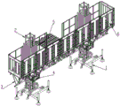
Fig. 1 is a three-dimensional assembly view of the middle bridge type electric lifting platform of the present invention;
FIG. 2 is a front view of FIG. 1;
FIG. 3 is a side view of FIG. 1;
FIG. 4 is a perspective view of the platform base of the present invention;
FIG. 5 is a perspective view of a middle standard knot of the present invention;
fig. 6 is a perspective view of a middle lifting device module according to the present invention;
FIG. 7 is a perspective view of a support beam for a middle platform according to the present invention;
fig. 8 is a perspective view of the telescopic platform of the present invention;
in the figure: 1-platform base, 11-chassis, 12-telescopic supporting legs, 13-moving wheels, 14-screw rods, 15-guide columns, 2-standard joint guide modules, 21-standard joints, 22-racks, 3-platform supporting beams, 31-bottom longitudinal beams, 32-top longitudinal beams, 33-top cross beams, 34-V-shaped supporting rods, 35-hinged lugs, 4-lifting device modules, 41-lifting device frames, 42-motors, 43-lifting plates, 44-guide grooves, 45-hinged lugs, 46-guide wheels, 5-telescopic platforms, 51-telescopic platform plates, 52-telescopic rods, 53-telescopic supporting rods, 6-protective guards and 7-special-shaped corrugated plates.
Detailed Description
The technical solutions in the embodiments of the present invention will be described clearly and completely with reference to the accompanying drawings in the embodiments of the present invention, and it is obvious that the described embodiments are only some embodiments of the present invention, not all embodiments. Based on the embodiments in the present invention, all other embodiments obtained by a person skilled in the art without creative work belong to the protection scope of the present invention.
The utility model aims at providing a bridge type electric lift platform to solve the problem that prior art exists.
In order to make the above objects, features and advantages of the present invention more comprehensible, the present invention is described in detail with reference to the accompanying drawings and the detailed description.
The bridge type electric lifting platform in this embodiment, as shown in fig. 1-3, includes a platform base 1, a standard joint guide module 2, a platform support beam 3, a lifting device module 4, a telescopic platform 5, and a guard rail 6; platform base 1 supports in the bottom of standard festival guide module 2, be provided with rack 22 along the direction of rise and fall on the standard festival guide module 2, hoisting device module 4 passes through the meshing of motor gear and rack 22 and is connected, a supporting beam of platform 3 is connected to hoisting device module 4's both sides, and with telescopic platform 5 between be connected through a supporting beam of platform 3, telescopic platform 5 sets up on a supporting beam of platform 3, rail guard 6 installs the periphery at hoisting device module 4 and a supporting beam of platform 3 through high strength bolt.
In this embodiment, the standard section guiding modules 2 are provided with two sets, and the bottoms of the two sets of standard section guiding modules 2 are provided with the platform base 1, the two sets of standard section guiding modules 2 are connected with a set of lifting device modules 4 respectively, the outer sides of the two sets of lifting device modules 4 are connected with the platform supporting beam 3, the inner sides of the two sets of lifting device modules opposite to each other are connected with each other through the platform supporting beam 3, and the telescopic platform 5 is arranged on the platform supporting beam 3 between the two sets of lifting device modules 4.
In this embodiment, as shown in fig. 4, the platform base 1 includes a chassis 11, telescopic legs 12 and moving wheels 13, the telescopic legs 12 are respectively disposed at four corners and the bottom center of the chassis 11, the telescopic legs 12 are connected to a guide post 15 with an internal thread on the chassis 11 through screws 14, the height of the telescopic legs 12 is adjusted by rotating the screws 14, and the bottom of the chassis 11 is provided with the four moving wheels 13. After the platform moves to the appointed place, through artifical rotatory flexible landing leg 12, hold up chassis 11, platform base 1 designs the atress good like this, and lift platform has more stability. When the platform needs to be moved, the telescopic supporting legs 12 are manually rotated, so that the movable wheels 13 are manually moved under the condition that the construction platform is not required to be completely disassembled after contacting the ground, and the platform is flexibly, quickly and conveniently moved. The platform base 1 is a base with moving wheels 13 and five telescopic legs 12 with telescopic and adjustable height, is convenient to move and is suitable for different foundation conditions.
In this embodiment, the standard knot guiding module 2 includes a plurality of standard knots 21 (as shown in fig. 5) of 1.5 meters vertically connected through high-strength bolts and a limiting non-standard knot (not shown in the figure) arranged at the top, the standard knot at the bottom is connected with the chassis 11 of the platform base 1 through high-strength bolts, and the top end of the limiting non-standard knot at the top is provided with a limiting block for preventing the lifting device module 4 from driving the platform to integrally ascend to the top and exceed the position of the standard knot 21.
In this embodiment, as shown in fig. 6, the lifting device module 4 includes a lifting device frame 41, a motor 42 with a motor gear, and a lifting plate 43, the lifting device frame 41 is laid with a plurality of special-shaped corrugated plates 7 at the top to form the lifting plate 43, the lifting plate 43 is provided with a square guide slot 44 at the inner side for matching with the standard knot 21, the standard knot 21 has an outer contour matching with the contour of the guide slot 44, the standard knot 21 is inserted into the guide slot 44, the motor 42 is provided on the lifting device frame 41 at the bottom of the lifting plate 43, at least two motors 42 are provided and vertically distributed on the lifting device frame 41, the motor gear at the inner end of the motor 42 is engaged with the rack 22 on the standard knot guide module 2; the guard rail 6 is connected to the outside of the lifter frame 41; the inside of hoisting device frame 41 still is provided with a plurality of leading wheels 46 with the frame roll connection of standard festival 21, wherein the top of hoisting device frame 41 is provided with a set of leading wheel respectively with the four corners opposite department of guide way 44, every group leading wheel includes two leading wheels 46, two leading wheels 46 of four groups leading wheels respectively with two lateral walls roll connection of four pillars of standard festival 21, the bottom of hoisting device frame 41 is provided with a set of leading wheel respectively with the both sides that the guide way 44 opening is relative, every group leading wheel includes two leading wheels 46, two leading wheels 46 of two groups leading wheels respectively with two lateral walls roll connection of two pillars of the inboard of standard festival 21. The lifting device module 4 is meshed with the rack 22 of the standard joint 21 through a motor gear and is driven by a motor 42 to lift up and down. The inside 12 leading wheels 46 of hoisting device frame 41 totally link up with standard festival 21 from top to bottom, play the direction when going up and down, spacing etc..
In the present embodiment, as shown in fig. 7, the platform supporting beam 3 includes a bottom longitudinal beam 31, two top longitudinal beams 32 and a top cross beam 33 sequentially arranged from bottom to top, the bottom longitudinal beam 31 is connected to the two top longitudinal beams 32 through a plurality of V-shaped supporting rods 34, and a plurality of top cross beams 33 are longitudinally distributed on the tops of the two top longitudinal beams 32; the two ends of the bottom longitudinal beam 31 and the two top longitudinal beams 32 are both provided with hinge lugs 35, the two adjacent platform supporting beams 3 are hinged through the hinge lugs 35 on the bottom longitudinal beam 31 and the top longitudinal beam 32, and the platform supporting beam 3 connected with the lifting device is hinged through the hinge lugs 35 on the bottom longitudinal beam 31 and the top longitudinal beam 32 and the hinge lugs 45 at the corresponding positions on the lifting device frame 41. Through the hinge lug between the platform supporting beam 3, between platform supporting beam 3 and the hoisting device, with the round pin hub connection, ann tears convenient and fast open, can rotate from top to bottom, and the flexibility ratio nature is high. Meanwhile, the required length can be formed to meet the construction requirement. Simple structure, light weight and low labor intensity.
In this embodiment, as shown in fig. 8, the retractable platform 5 includes a retractable platform plate 51, a retractable rod 52 and a retractable support rod 53, the retractable rod 52 replaces the top beam 33 of the platform support beam 3 supporting the retractable platform 5 and is disposed on the top of the two top longitudinal beams 32, the retractable rod 52 is connected to the bottom longitudinal beam 31 of the platform support beam 3 through the retractable support rod 53, and the plurality of special-shaped corrugated plates 7 are laid on the top of the retractable rod 52 to form the retractable platform plate 51. The installation of the telescopic platform plate 51 is to install the telescopic support rods 53 on the platform support beam 3, then to lift off the top cross beam 33 on the platform support beam 3, and finally to lay the telescopic platform plate 51 manually, and to lay according to the required size of construction. Therefore, the construction requirements of recessed empty shaft holes such as bay windows and balcony spaces of buildings can be met. People stand on the platform plate for construction as in a room, and the construction method is safe and reliable. The telescopic rod 52 and the telescopic support rod 53 are made into telescopic structures (which can comprise two parts of a main rod body and a telescopic rod 52 body, the telescopic rod 52 body part can extend or retract in the main rod body, and is positioned by a limit pin, the specific telescopic structure is a conventional means, a view is not shown), and the telescopic platform 5 can be extended according to the size requirement, and the length range of the telescopic platform 5 can be specifically 0.2 m-1 m.
The utility model discloses the principle and the implementation mode of the utility model are explained by applying the concrete examples, and the explanation of the above examples is only used for helping to understand the method and the core idea of the utility model; meanwhile, for the general technical personnel in the field, according to the idea of the present invention, there are changes in the concrete implementation and the application scope. In summary, the content of the present description should not be construed as a limitation of the present invention.
Claims (8)
1. The utility model provides a bridge type electric lift platform which characterized in that: the device comprises a platform base, a standard knot guide module, a platform supporting beam, a lifting device module, a telescopic platform and a protective guard; the platform base support in the bottom of standard festival guide module, be provided with the rack along the direction of rise and fall on the standard festival guide module, the hoisting device module pass through motor gear with rack toothing connects, the both sides of hoisting device module are connected a platform supporting beam, and with pass through between the flexible platform a platform supporting beam connects, flexible platform set up in on the platform supporting beam, the rail guard set up in the hoisting device module with platform supporting beam's periphery.
2. A bridge motorized lift platform as set forth in claim 1, wherein: the standard festival direction module is provided with two sets ofly, and is two sets of the bottom of standard festival direction module all is provided with the platform base, it is two sets of connect a set ofly respectively on the standard festival direction module the hoisting device module, it is two sets of the outside of hoisting device module is connected with a platform supporting beam, it is two sets of the relative inboard of hoisting device module is passed through a platform supporting beam connects, just flexible platform sets up in two sets of between the hoisting device module on the platform supporting beam.
3. A bridge motorized lift platform as set forth in claim 2, wherein: the platform base comprises a chassis, telescopic supporting legs and moving wheels, the telescopic supporting legs are arranged at four corners of the chassis and at the center of the bottom of the chassis respectively, the telescopic supporting legs are connected with guide pillars with internal threads on the chassis through screws, the heights of the telescopic supporting legs are adjusted by rotating the screws, and the four moving wheels are arranged at the bottom of the chassis.
4. A bridge motorized lift platform as set forth in claim 3, wherein: the standard knot guide module comprises a plurality of 1.5-meter standard knots vertically connected through high-strength bolts and limiting non-standard knots arranged at the top, the bottom of each standard knot is connected with the chassis of the platform base through the high-strength bolts, and the top of each limiting non-standard knot is provided with a limiting block used for preventing the lifting device module from driving the platform to integrally ascend to the top and exceed the position of each standard knot.
5. A bridge motorized lift platform as set forth in claim 2, wherein: the lifting device module comprises a lifting device frame, a motor with a motor gear and a lifting plate, the lifting plate is paved by a plurality of special-shaped corrugated plates at the top of the lifting device frame, a guide groove matched with the standard knot is formed in the inner side of the lifting plate, the standard knot is inserted into the guide groove, the motor is arranged on the lifting device frame at the bottom of the lifting plate, at least two motors are arranged and vertically distributed on the lifting device frame, and the motor gear at the inner end of each motor is meshed and connected with a rack on the standard knot guide module; the guard rail is connected to an outer side of the lifting device frame.
6. A bridge motorized lift platform as set forth in claim 5 in which: the inboard of hoisting device frame still be provided with a plurality of with the frame roll connection's of standard festival leading wheel, wherein the top of hoisting device frame with the relative department in four corners of guide way is provided with a set of leading wheel respectively, and every leading wheel of group includes two leading wheels, four leading wheels of group respectively with two lateral wall roll connection of four pillars of standard festival, the bottom of hoisting device frame with the both sides that the guide way opening is relative are provided with a set of leading wheel respectively, and every leading wheel of group includes two leading wheels, two leading wheels of two sets of leading wheels respectively with two lateral wall roll connection of two pillars of the inboard of standard festival.
7. A bridge motorized lift platform as set forth in claim 5 in which: the platform supporting beam comprises a bottom longitudinal beam, two top longitudinal beams and a top cross beam which are sequentially arranged from bottom to top, the bottom longitudinal beam is connected with the two top longitudinal beams through a plurality of V-shaped supporting rods, and a plurality of top cross beams are longitudinally distributed at the tops of the two top longitudinal beams; the two ends of the bottom longitudinal beam and the two ends of the top longitudinal beam are both provided with hinged lugs, the platform supporting beams are connected in a hinged mode through the bottom longitudinal beam and the hinged lugs on the top longitudinal beam, and the platform supporting beams connected with the lifting device are connected in a hinged mode through the hinged lugs on the bottom longitudinal beam and the top longitudinal beam and the hinged lugs at the corresponding positions on the lifting device frame.
8. A bridge motorized lift platform as set forth in claim 7 in which: the telescopic platform includes flexible landing slab, telescopic link and flexible bracing piece, the telescopic link replacement supports flexible platform a platform supporting beam's top crossbeam sets up in two the top of top longeron, the telescopic link passes through flexible bracing piece is connected a platform supporting beam's end longeron, a plurality of special-shaped wave plates lay in the top of telescopic link constitutes flexible landing slab.
Priority Applications (1)
| Application Number | Priority Date | Filing Date | Title |
|---|---|---|---|
| CN202023299303.8U CN214270151U (en) | 2020-12-31 | 2020-12-31 | Bridge type electric lifting platform |
Applications Claiming Priority (1)
| Application Number | Priority Date | Filing Date | Title |
|---|---|---|---|
| CN202023299303.8U CN214270151U (en) | 2020-12-31 | 2020-12-31 | Bridge type electric lifting platform |
Publications (1)
| Publication Number | Publication Date |
|---|---|
| CN214270151U true CN214270151U (en) | 2021-09-24 |
Family
ID=77786191
Family Applications (1)
| Application Number | Title | Priority Date | Filing Date |
|---|---|---|---|
| CN202023299303.8U Active CN214270151U (en) | 2020-12-31 | 2020-12-31 | Bridge type electric lifting platform |
Country Status (1)
| Country | Link |
|---|---|
| CN (1) | CN214270151U (en) |
-
2020
- 2020-12-31 CN CN202023299303.8U patent/CN214270151U/en active Active
Similar Documents
| Publication | Publication Date | Title |
|---|---|---|
| CN113789948B (en) | Large-span atrium side wall sliding rail hanging basket with roof and construction method thereof | |
| CN111502219A (en) | Bearing frame for building construction | |
| CN211143939U (en) | Tower mast structure lift operation platform | |
| CN114150857B (en) | Construction method of attached type automatic climbing elevator shaft safety protection platform | |
| CN216476193U (en) | Portable steel member installation operation platform of modularization | |
| CN107514145A (en) | A kind of removable steel roofing liner installation construction device and method | |
| CN214270151U (en) | Bridge type electric lifting platform | |
| CN109653484B (en) | Roofing superelevation faces external hanging flower basket mounting structure of empty curtain engineering | |
| LU501395B1 (en) | Bridge electric lifting platform | |
| CN217054267U (en) | Protection device construction structure | |
| CN110552541A (en) | Tower mast structure lift operation platform | |
| CN113175222B (en) | Method for installing embedded prefabricated external wall panel component | |
| CN213356779U (en) | Overweight steel column translation transportation installation device | |
| CN211257769U (en) | Truss bridging based on attached lifting platform | |
| CN210561720U (en) | Pier stud maintenance repair operation platform | |
| CN210563531U (en) | Steel structure support for building protection | |
| CN111946047A (en) | A protection adjustable shelter covering or awning on a car, boat, etc. for building scaffold | |
| CN112796498A (en) | Double-column type electric construction platform with truss girder and working method thereof | |
| CN219569531U (en) | Construction platform for additionally installing elevator | |
| CN111305433A (en) | Construction structure and construction method of inclined glass curtain wall of roof steel structure platform | |
| CN217555608U (en) | Auxiliary hanging bracket for steel structure installation | |
| CN220768987U (en) | Building construction platform capable of expanding working space | |
| CN219808939U (en) | Expressway tunnel fireproof construction device | |
| CN216380480U (en) | Integral movable operation frame | |
| CN215978364U (en) | A remove measure frame for installing wall profiled sheet |
Legal Events
| Date | Code | Title | Description |
|---|---|---|---|
| GR01 | Patent grant | ||
| GR01 | Patent grant |