CN213763396U - Industrial waste renewable resources recovery device - Google Patents
Industrial waste renewable resources recovery device Download PDFInfo
- Publication number
- CN213763396U CN213763396U CN202022051994.3U CN202022051994U CN213763396U CN 213763396 U CN213763396 U CN 213763396U CN 202022051994 U CN202022051994 U CN 202022051994U CN 213763396 U CN213763396 U CN 213763396U
- Authority
- CN
- China
- Prior art keywords
- fixed
- shell
- industrial waste
- casing
- hydraulic cylinder
- Prior art date
- Legal status (The legal status is an assumption and is not a legal conclusion. Google has not performed a legal analysis and makes no representation as to the accuracy of the status listed.)
- Active
Links
Images


Classifications
-
- Y—GENERAL TAGGING OF NEW TECHNOLOGICAL DEVELOPMENTS; GENERAL TAGGING OF CROSS-SECTIONAL TECHNOLOGIES SPANNING OVER SEVERAL SECTIONS OF THE IPC; TECHNICAL SUBJECTS COVERED BY FORMER USPC CROSS-REFERENCE ART COLLECTIONS [XRACs] AND DIGESTS
- Y02—TECHNOLOGIES OR APPLICATIONS FOR MITIGATION OR ADAPTATION AGAINST CLIMATE CHANGE
- Y02W—CLIMATE CHANGE MITIGATION TECHNOLOGIES RELATED TO WASTEWATER TREATMENT OR WASTE MANAGEMENT
- Y02W30/00—Technologies for solid waste management
- Y02W30/20—Waste processing or separation
Abstract
The utility model discloses an industrial waste recycling resource recovery unit belongs to resource recovery technical field, which comprises a housin, the motor is installed to a side symmetry of casing, the output shaft of motor is fixed with the pivot, be fixed with the action wheel in the pivot, the symmetry is provided with from the driving wheel on the casing, and is two sets of all rotate with the casing from the driving wheel and be connected, it has the chain to mesh between driving wheel and the action wheel, one side of baffle is fixed with the disc, the outside of disc is fixed with the tooth piece. The utility model discloses can protect rolling the roller upper portion when recovery unit pulverizes the discarded object, to splashing piece or fragment around when preventing to roll the discarded object, alleviate the work load of clearance, two blocks of baffles can be to the discarded object intermittent type nature extrusion of piling on rolling the roller and promote in addition for the discarded object is pressed close to and then is pulverized more easily with rolling the roller, pulverizes work convenient and fast more, labour saving and time saving, thereby provides convenience for people's use.
Description
Technical Field
The utility model relates to a recovery unit especially relates to an industrial waste renewable resources recovery unit, belongs to resource recovery technical field.
Background
The renewable resources are the material resources which can be repeatedly recycled and reused after being developed and used once and discarded, and comprise iron and steel, nonferrous metals, rare metals, alloys, inorganic nonmetal, plastics, rubber, fibers, paper and the like which are produced and discarded by taking minerals as raw materials. Compared with the use of the original resources, the use of the renewable resources can save a large amount of energy, water resources and production auxiliary materials, reduce the production cost and reduce the environmental pollution; according to incomplete statistics, the recyclable waste in China can reach 600 million tons every year, and if the recyclable waste is treated as garbage, resources are wasted, and more importantly, environmental pollution is caused. Therefore, various renewable resource recovery devices are designed in the prior art for recovering wastes;
including two axis of rotation usually among the traditional recovery unit, put the discarded object of retrieving in the axis of rotation and drive the roller that rolls by the axis of rotation and crush the discarded object, but some discarded objects can spill the device outside by the piece that the in-process that crushes produced, cause ground contaminated, spatter or pound the staff who comes even, some discarded objects are in addition because the volume is great or the quality is too light difficult for getting into between the roller that rolls, roll the roller and crush the difficulty, still need the manual work to intervene sometimes, it is very inconvenient to use, waste time and energy.
SUMMERY OF THE UTILITY MODEL
The utility model mainly aims at providing an industrial waste renewable resources recovery unit to solve and roll the problem that the difficulty just smashes and easily splashes among the prior art.
The purpose of the utility model can be achieved by adopting the following technical scheme:
the utility model provides an industrial waste renewable resources recovery device, includes the casing, the motor is installed to one side symmetry of casing, the output shaft of motor is fixed with the pivot, be fixed with the action wheel in the pivot, the symmetry is provided with from the driving wheel on the casing, and is two sets of all rotate with the casing from the driving wheel and be connected, it has the chain to mesh between driving wheel and the action wheel, be fixed with the gear from the driving wheel, it is connected with the baffle to rotate on the casing, one side of baffle is fixed with the disc, the outside of disc is fixed with the tooth piece, tooth piece and gear engagement, the top symmetry of casing is provided with the fixed plate, be fixed with first spring between baffle and the fixed plate, the one end of pivot is fixed with the roller that rolls, be provided with on the casing and promote extrusion mechanism, the bottom of casing is provided with the collection subassembly.
Preferably: the utility model discloses a push extrusion mechanism, including casing, pneumatic cylinder, baffle, push plate, baffle, frame, push plate and connection rope, push mechanism includes dog, pneumatic cylinder and frame, the dog is located the inside of casing, the pneumatic cylinder is located the inside wall of casing, the flexible end of pneumatic cylinder is fixed with the push pedal, one side that the push pedal is close to the pneumatic cylinder is fixed with the closure plate, one side symmetry that the push pedal is close to the pneumatic cylinder is fixed with the connection rope, the one end of connecting the rope is fixed with the baffle, the bottom symmetry of baffle is provided with the second spring, and is two sets of connect the rope and run through the inside of two sets of second springs respectively and extend to the bottom of baffle, the frame is located the bottom of casing, the inside sliding connection of baffle and frame.
Preferably: the collecting assembly comprises a fixing frame and a collecting box, the fixing frame is located at the bottom of the shell, and the collecting box is movably connected inside the fixing frame.
Preferably: one side of the collecting box is provided with a handle, and an anti-slip ring is arranged on the handle.
Preferably: a goods taking opening is formed in one side of the shell, and a movable door is arranged inside the goods taking opening.
Preferably: one end of the rotating shaft penetrates through the inside of the shell and extends to the inside of the shell, and the rotating shaft is rotatably connected with the shell.
The utility model has the advantages that:
the utility model provides a pair of industrial waste renewable resources recovery unit: through the mutual cooperation of the motor, the rotating shaft, the driving wheel, the driven wheel, the chain, the gear, the baffle, the disc, the fixed plate and the first spring, the upper part of the rolling roller can be protected when the recovery device crushes the waste, the splash of fragments or fragments around the waste can be prevented when the waste is rolled, the cleaning workload can be reduced, in addition, the waste stacked on the rolling roller can be intermittently extruded and pushed by the two baffles, the waste is pressed close to the rolling roller and is crushed more easily, the crushing work is more convenient and faster, the time and the labor are saved, and convenience is brought to the use of people; through the mutual matching use of the stop block, the hydraulic cylinder, the push plate, the blocking plate, the connecting rope, the partition plate, the second spring and the outer frame, the compression block of the extruded and formed waste can be taken out while the crushing work is carried out, and the normal crushing work cannot be influenced, so that the processing time is saved, the working efficiency is improved, and the production and processing requirements of enterprises are met; through the use of mutually supporting of fixed frame and collection box, can collect the piece of extrusion not when taking out discarded object compression piece, prevent that the piece from dropping ground, increase staff's work load, collect moreover and get up easier processing to facilitate for the staff provides.
Drawings
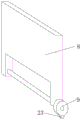
Fig. 1 is a front view of the present invention;
FIG. 2 is a schematic view of the connection between the motor and the rotating shaft of the present invention;
FIG. 3 is a front cross-sectional view of the present invention;
fig. 4 is a schematic view of the baffle of the present invention.
In the figure: 1. a housing; 2. a motor; 3. a rotating shaft; 4. a driving wheel; 5. a driven wheel; 6. a chain; 7. a gear; 8. a baffle plate; 9. a disc; 10. a fixing plate; 11. a first spring; 12. rolling a roller; 13. a stopper; 14. a hydraulic cylinder; 15. pushing the plate; 16. a blocking plate; 17. connecting ropes; 18. a partition plate; 19. a second spring; 20. an outer frame; 21. a fixing frame; 22. a collection box; 23. a tooth block.
Detailed Description
In order to make the technical solutions of the present invention clearer and clearer for those skilled in the art, the present invention will be described in further detail with reference to the following embodiments and drawings, but the embodiments of the present invention are not limited thereto.
As shown in fig. 1-4, this embodiment provides an industrial waste recycling device, which includes a housing 1, a motor 2 is symmetrically installed on one side of the housing 1, a rotating shaft 3 is fixed to an output shaft of the motor 2, a driving wheel 4 is fixed to the rotating shaft 3, driven wheels 5 are symmetrically arranged on the housing 1, two sets of driven wheels 5 are rotatably connected to the housing 1, a chain 6 is engaged between the driven wheels 5 and the driving wheel 4, a gear 7 is fixed to the driven wheels 5, a baffle 8 is rotatably connected to the housing 1, a disc 9 is fixed to one side of the baffle 8, a toothed block 23 is fixed to the outer side of the disc 9, the toothed block 23 is engaged with the gear 7, a fixing plate 10 is symmetrically arranged on the top of the housing 1, a first spring 11 is fixed between the baffle 8 and the fixing plate 10, a rolling roller 12 is fixed to one end of the rotating shaft 3, a pushing and squeezing mechanism is arranged on the housing 1, and a collecting assembly is arranged at the bottom of the housing 1.
In this embodiment, as shown in fig. 3, the pushing and squeezing mechanism includes a stopper 13, a hydraulic cylinder 14 and an outer frame 20, the stopper 13 is located inside the housing 1, the hydraulic cylinder 14 is located inside the housing 1, a push plate 15 is fixed to a telescopic end of the hydraulic cylinder 14, a blocking plate 16 is fixed to a side of the push plate 15 close to the hydraulic cylinder 14, a connecting rope 17 is symmetrically fixed to a side of the push plate 15 close to the hydraulic cylinder 14, a partition plate 18 is fixed to one end of the connecting rope 17, second springs 19 are symmetrically arranged at a bottom of the partition plate 18, two sets of connecting ropes 17 respectively penetrate through an inside of the two sets of second springs 19 and extend to a bottom of the partition plate 18, the outer frame 20 is located at a bottom of the housing 1, the partition plate 18 is slidably connected to an inside of the outer frame 20, the waste slag crushed by the crushing roller 12 falls between the push plate 15 and the partition plate 18, when the push plate 15 and the partition plate 18 are fully stacked, the hydraulic cylinder 14 is started, the hydraulic cylinder 14 drives the push plate 15 to move leftward, the push plate 15 pulls the connecting rope 17 in the moving process, the connecting rope 17 can pull the partition plate 18 to move downwards, when the top of the partition plate 18 is aligned with the inner bottom wall of the shell 1, the push plate 15 also extrudes waste slag, meanwhile, the blocking plate 16 on the right side of the push plate 15 blocks the waste slag at the position of the block 13, the hydraulic cylinder 14 is started again, the hydraulic cylinder 14 drives the push plate 15 to move rightwards, the partition plate 18 recovers to the original position under the action of the elastic force of the second spring 19 to block the waste slag which is not extruded, at the moment, the door of the device can be opened to take out the waste blocks which are subjected to compression molding, the waste compression blocks which are subjected to extrusion molding can be taken out when the crushing work is carried out, the normal crushing work cannot be influenced, the processing time is saved, and the working efficiency is improved.
In this embodiment, as shown in fig. 3, the collecting component includes fixed frame 21 and collection box 22, fixed frame 21 is located the bottom of casing 1, the inside swing joint of fixed frame 21 has collection box 22, when the discarded object piece takes out, can fall some along with it and do not have fashioned piece, the piece can drop in collecting box 22, can take out collection box 22 at any time when collecting box 22 and amasss its unified processing, prevent that the piece from dropping ground, increase staff's work load, and collect and handle more easily, thereby provide convenience for the staff.
In this embodiment, as shown in fig. 3, a handle is provided on one side of the collection box 22, and an anti-slip ring is provided on the handle, so that the handle can be pulled conveniently to take out the collection box 22.
In this embodiment, as shown in fig. 3, a goods taking opening is opened at one side of the housing 1, and a movable door is disposed inside the goods taking opening, so that the waste compression block can be conveniently taken out.
In the present embodiment, as shown in fig. 2-3, one end of the rotating shaft 3 penetrates through the inside of the housing 1 and extends to the inside of the housing 1, and the rotating shaft 3 is rotatably connected with the housing 1.
As shown in fig. 1 to 4, the present embodiment provides an industrial waste recycling apparatus, which operates as follows:
step 1: starting a motor 2, pouring the waste on the top of a rolling roller 12, driving the rolling roller 12 to rotate by the motor 2 through a rotating shaft 3, grinding the waste, driving a driving wheel 4 to rotate by the motor 2 through the rotating shaft 3, driving a driven wheel 5 to rotate by the driving wheel 4 through a chain 6, and stirring a toothed block 23 on a disc 9 to rotate by the driven wheel 5 through a gear 7, so that the disc 9 intermittently rotates, the top of a baffle 8 on the disc 9 rotates and pushes the baffle 8 to push the waste upwards, the waste is pushed to the rolling roller 12 to be close, the waste is ground more quickly, meanwhile, under the elastic force action of a first spring 11, the baffle 8 can be restored to the original position, and meanwhile, common scraps and crushed slag can be blocked in the device in the moving;
step 2: the waste slag crushed by the rolling roller 12 falls between the push plate 15 and the partition plate 18, when the push plate 15 and the partition plate 18 are fully stacked, the hydraulic cylinder 14 is started, the hydraulic cylinder 14 drives the push plate 15 to move leftwards, the connecting rope 17 is pulled by the push plate 15 in the moving process, the partition plate 18 is pulled by the connecting rope 17 to move downwards, when the top of the partition plate 18 is aligned with the inner bottom wall of the shell 1, the waste slag is also extruded by the push plate 15, meanwhile, the waste slag at the position of the stop block 13 is blocked by the blocking plate 16 at the right side of the push plate 15, the hydraulic cylinder 14 is started again, the hydraulic cylinder 14 drives the push plate 15 to move rightwards, the partition plate 18 is restored under the elastic force of the second spring 19 to block the waste slag which is not extruded, and at the moment, the door of the device can be opened to take out the waste blocks which are compressed and formed;
and step 3: when the waste material is taken out, some non-formed fragments can fall along with the waste material, the fragments can fall into the collecting box 22, and when the collecting box 22 is full, the collecting box 22 can be taken out at any time for uniform treatment.
The above description is only a further embodiment of the present invention, but the scope of protection of the present invention is not limited thereto, and any person skilled in the art can replace or change the technical solution and the concept of the present invention within the scope of the present invention.
Claims (6)
1. The utility model provides an industrial waste renewable resources recovery unit which characterized in that: comprises a shell (1), a motor (2) is symmetrically installed on one side of the shell (1), a rotating shaft (3) is fixed on an output shaft of the motor (2), a driving wheel (4) is fixed on the rotating shaft (3), a driven wheel (5) is symmetrically arranged on the shell (1), the driven wheel (5) is connected with the shell (1) in a rotating mode, a chain (6) is meshed between the driven wheel (5) and the driving wheel (4), a gear (7) is fixed on the driven wheel (5), a baffle (8) is connected on the shell (1) in a rotating mode, a disc (9) is fixed on one side of the baffle (8), a tooth block (23) is fixed on the outer side of the disc (9), the tooth block (23) is meshed with the gear (7), a fixing plate (10) is symmetrically arranged on the top of the shell (1), and a first spring (11) is fixed between the baffle (8) and the fixing plate (10), the one end of pivot (3) is fixed with rolls roller (12), be provided with on casing (1) and promote extrusion mechanism, the bottom of casing (1) is provided with the collection subassembly.
2. The recycling device of industrial waste recycling resources according to claim 1, characterized in that: the pushing and extruding mechanism comprises a stop block (13), a hydraulic cylinder (14) and an outer frame (20), the stop block (13) is positioned inside the shell (1), the hydraulic cylinder (14) is positioned on the inner side wall of the shell (1), a push plate (15) is fixed at the telescopic end of the hydraulic cylinder (14), a blocking plate (16) is fixed at one side of the push plate (15) close to the hydraulic cylinder (14), connecting ropes (17) are symmetrically fixed on one side of the push plate (15) close to the hydraulic cylinder (14), a partition plate (18) is fixed at one end of each connecting rope (17), second springs (19) are symmetrically arranged at the bottom of the partition plate (18), the two groups of connecting ropes (17) respectively penetrate through the interiors of the two groups of second springs (19) and extend to the bottom of the partition plate (18), the outer frame (20) is positioned at the bottom of the shell (1), and the partition board (18) is connected with the inner part of the outer frame (20) in a sliding manner.
3. The recycling device of industrial waste recycling resources according to claim 1, characterized in that: the collection subassembly is including fixed frame (21) and collection box (22), fixed frame (21) are located the bottom of casing (1), the inside swing joint of fixed frame (21) has collection box (22).
4. The recycling device of industrial waste recycling resources according to claim 3, characterized in that: one side of the collecting box (22) is provided with a handle, and the handle is provided with an anti-skid ring.
5. The recycling device of industrial waste recycling resources according to claim 1, characterized in that: a goods taking opening is formed in one side of the shell (1), and a movable door is arranged inside the goods taking opening.
6. The recycling device of industrial waste recycling resources according to claim 1, characterized in that: one end of the rotating shaft (3) penetrates through the inside of the shell (1) and extends to the inside of the shell (1), and the rotating shaft (3) is rotatably connected with the shell (1).
Priority Applications (1)
| Application Number | Priority Date | Filing Date | Title |
|---|---|---|---|
| CN202022051994.3U CN213763396U (en) | 2020-09-17 | 2020-09-17 | Industrial waste renewable resources recovery device |
Applications Claiming Priority (1)
| Application Number | Priority Date | Filing Date | Title |
|---|---|---|---|
| CN202022051994.3U CN213763396U (en) | 2020-09-17 | 2020-09-17 | Industrial waste renewable resources recovery device |
Publications (1)
| Publication Number | Publication Date |
|---|---|
| CN213763396U true CN213763396U (en) | 2021-07-23 |
Family
ID=76905108
Family Applications (1)
| Application Number | Title | Priority Date | Filing Date |
|---|---|---|---|
| CN202022051994.3U Active CN213763396U (en) | 2020-09-17 | 2020-09-17 | Industrial waste renewable resources recovery device |
Country Status (1)
| Country | Link |
|---|---|
| CN (1) | CN213763396U (en) |
Cited By (1)
| Publication number | Priority date | Publication date | Assignee | Title |
|---|---|---|---|---|
| CN114798075A (en) * | 2022-04-21 | 2022-07-29 | 王文超 | Environment-friendly energy-saving solid waste treatment device and working method thereof |
-
2020
- 2020-09-17 CN CN202022051994.3U patent/CN213763396U/en active Active
Cited By (2)
| Publication number | Priority date | Publication date | Assignee | Title |
|---|---|---|---|---|
| CN114798075A (en) * | 2022-04-21 | 2022-07-29 | 王文超 | Environment-friendly energy-saving solid waste treatment device and working method thereof |
| CN114798075B (en) * | 2022-04-21 | 2023-12-29 | 阜新建兴金属有限公司 | Environment-friendly energy-saving solid waste treatment device and working method thereof |
Similar Documents
| Publication | Publication Date | Title |
|---|---|---|
| CN114345455B (en) | Waste recovery device for building engineering | |
| CN110918180A (en) | Waste material separation recovery unit who contains metalliferous material | |
| CN213763396U (en) | Industrial waste renewable resources recovery device | |
| CN211989086U (en) | Construction waste treatment equipment | |
| CN214554268U (en) | Building rubbish reducing mechanism | |
| CN110102385B (en) | Domestic waste recovery unit | |
| CN212441496U (en) | Medical waste treatment device | |
| CN112403587A (en) | Solid waste high-strength integrated compression equipment based on environmental protection | |
| CN111203311A (en) | Residential household garbage treatment equipment | |
| CN203389697U (en) | Waste material crushing machine | |
| CN114177978B (en) | Environment-friendly waste paper recycling crushing equipment | |
| CN212758821U (en) | Categorised recovery crushing apparatus of paper products | |
| CN213996057U (en) | Solid waste recycling treatment device convenient to recycle | |
| CN209935503U (en) | Garbage crushing device convenient for discharging | |
| CN211467103U (en) | Smashing device for recycling plastic garbage | |
| CN208661327U (en) | A kind of building waste grinding device easy to repair | |
| CN217289756U (en) | Industrial waste renewable resources recovery device | |
| CN213767325U (en) | Recycling and flattening machine for renewable resources | |
| CN111282649A (en) | Solid garbage classification treatment device for cities and towns | |
| CN112718049A (en) | Remove stone machine degree of depth rubble device | |
| CN206881797U (en) | A kind of urban architecture solid refuse processing disintegrating machine | |
| CN214439723U (en) | Waste paper smashing device for consulting of occupational health safety management system | |
| CN220277080U (en) | Scrap steel and iron slag recovery device | |
| CN213436286U (en) | Crushing apparatus for recycling degraded materials | |
| CN220027164U (en) | Cement kiln co-treatment household garbage device |
Legal Events
| Date | Code | Title | Description |
|---|---|---|---|
| GR01 | Patent grant | ||
| GR01 | Patent grant |