CN212831474U - Multifunctional platform for detecting machine - Google Patents
Multifunctional platform for detecting machine Download PDFInfo
- Publication number
- CN212831474U CN212831474U CN202020974664.9U CN202020974664U CN212831474U CN 212831474 U CN212831474 U CN 212831474U CN 202020974664 U CN202020974664 U CN 202020974664U CN 212831474 U CN212831474 U CN 212831474U
- Authority
- CN
- China
- Prior art keywords
- plate
- conveying
- suction
- sliding
- correcting
- Prior art date
- Legal status (The legal status is an assumption and is not a legal conclusion. Google has not performed a legal analysis and makes no representation as to the accuracy of the status listed.)
- Active
Links
Images


Abstract
The utility model discloses a multifunctional platform for detection machine, including frame, conveying mechanism, drop feed mechanism, suction disc mechanism: the working area of the rack is divided into a conveying area and at least two material placing areas; the conveying mechanism is arranged in the conveying area; the discharging mechanism is arranged in the discharging area; the suction plate mechanism is arranged on the linear guide rail assembly and used for sucking, grabbing and placing materials on the conveying mechanism on the discharging mechanism; the conveying mechanism conveys the circuit boards which are detected into the conveying area, the discharging area is partitioned according to detection results, and the suction plate mechanism places the circuit boards on the discharging mechanisms in different areas according to different detection results of the circuit boards, so that partition management of the circuit boards is achieved.
Description
Technical Field
The utility model relates to a circuit board processing technology field, in particular to multifunctional platform for detecting machine.
Background
Due to production requirements, test results with different technical requirements, such as different signals of normal, less, larger and the like, can appear behind the circuit board detector, and the plate needs to be placed at different positions, so that manual plate separation is reduced.
SUMMERY OF THE UTILITY MODEL
The utility model discloses aim at solving one of the technical problem that exists among the prior art at least. Therefore, the utility model provides a multifunctional platform for detecting machine can place the circuit board after detecting in the position of difference.
According to the utility model discloses an detect machine multifunctional platform, including frame, conveying mechanism, drop feed mechanism, suction disc mechanism: the working area of the rack is divided into a conveying area and at least two material placing areas; the conveying mechanism is arranged in the conveying area; the discharging mechanism is arranged in the discharging area; the suction plate mechanism is arranged on the linear guide rail assembly, the linear guide rail assembly is fixed on the rack, and the suction plate mechanism adsorbs, grabs and places materials on the conveying mechanism on the discharging mechanism.
According to the utility model discloses multifunctional platform for detecting machine has following beneficial effect at least:
the conveying mechanism conveys the circuit boards which are detected into the conveying area, the discharging area is partitioned according to detection results, and the suction plate mechanism places the circuit boards on the discharging mechanisms in different areas according to different detection results of the circuit boards, so that partition management of the circuit boards is achieved.
According to some embodiments of the present invention, the conveying mechanism comprises a conveying roller set, a conveying baffle, a correcting splint assembly; the conveying roller group is formed by a plurality of conveying rubber rollers which are arranged in parallel, and the conveying rubber rollers are connected in series and driven by a first servo motor; the conveying baffle is positioned in the rear area of the conveying roller group and arranged between the conveying rubber rollers; the correcting clamp plate assembly is located in the front area of the conveying roller group.
According to some embodiments of the present invention, the correcting splint assembly comprises a correcting splint, a left fixing seat plate, a right fixing seat plate, a guide rod, and a driving pulley; the correcting clamp plates are divided into a left correcting clamp plate and a right correcting clamp plate, and the left correcting clamp plate and the right correcting clamp plate are respectively positioned on the left side and the right side of the conveying baffle plate; the left fixing seat plate is used for fixedly mounting the left correcting splint, and two left bearing sliding seats are mounted at the bottom of the left fixing seat plate; the right fixing seat plate is used for fixedly mounting the right correcting clamp plate, and two right bearing sliding seats are arranged at the bottom of the right fixing seat plate; the guide rods are respectively inserted into the left bearing sliding seat and the right bearing sliding seat; the transmission belt comprises two transmission belt pulleys, a transmission belt ring is arranged between the two transmission belt pulleys, and the front section and the rear section of the transmission belt ring are respectively connected with the left bearing sliding seat and the right bearing sliding seat.
According to some embodiments of the present invention, the discharging mechanism comprises a lifting seat plate, a screw nut, and a reduction motor; the front side of the lifting seat plate is provided with a rubber plate support plate in an arrangement mode, and the rear side of the lifting seat plate is provided with an installation plate; the screw rod nut is fixed in the center of the mounting plate, a lifting screw rod is arranged on the screw rod nut, the top of the lifting screw rod is connected with the rack through a connecting seat bearing, and a driven bevel gear is arranged at the bottom of the lifting screw rod; and the reduction motor is provided with a driving bevel gear meshed with the driven bevel gear.
According to the utility model discloses a some embodiments, be equipped with on the mounting panel and be located the linear bearing of screw-nut both sides, the last guide bar that is equipped with of linear bearing, the guide bar top through the axle center seat with the frame is connected, the guide bar bottom is fixed with the bottom plate, the bottom plate with gear motor connects.
According to some embodiments of the present invention, the suction plate mechanism comprises an installation platen, a lifting cylinder, a connecting rod, a suction rod arm, and a suction rod; the upper part of the mounting bedplate is connected with the linear guide rail assembly; the lifting cylinder is fixed on the installation bedplate, and a piston rod of the lifting cylinder penetrates through the installation bedplate to extend to the lower part of the installation bedplate; the connecting rod is arranged below the mounting bedplate and is connected with a piston rod of the lifting cylinder; the suction rod arms are arranged on the connecting rod and are perpendicular to the connecting rod; the suction rods are arranged on the suction rod arms.
According to some embodiments of the invention, the linear guide rail assembly comprises a linear motor, a slide rail; a sliding bedplate is arranged on the linear motor; the sliding rail and the linear motor are arranged in parallel, a sliding block is arranged on the sliding rail, a sliding plate is arranged between the sliding block and the sliding bedplate, and the sliding plate is connected with the installation bedplate through a vertical rod.
According to some embodiments of the utility model, still draw the car including removing, remove and draw and arrange on the car and install L shape bracing piece, when removing and drawing the car and pushing in the offset plate extension board inserts between the L shape bracing piece.
Additional aspects and advantages of the invention will be set forth in part in the description which follows and, in part, will be obvious from the description, or may be learned by practice of the invention.
Drawings
The above and/or additional aspects and advantages of the present invention will become apparent and readily appreciated from the following description of the embodiments, taken in conjunction with the accompanying drawings of which:
fig. 1 is a schematic perspective view of an embodiment of the present invention;
FIG. 2 is a schematic view of the transport mechanism shown in FIG. 1;
FIG. 3 is a schematic top view of the conveyor mechanism shown in FIG. 1;
FIG. 4 is a schematic bottom view of the conveyor mechanism shown in FIG. 1;
FIG. 5 is a schematic view of a calibration cleat assembly of the delivery mechanism shown in FIG. 1;
FIG. 6 is a schematic view of the combined state of the drop feed mechanism and the mobile pull cart shown in FIG. 1;
FIG. 7 is a schematic front view of the drop feed mechanism shown in FIG. 1;
FIG. 8 is a schematic rear view of the drop feed mechanism shown in FIG. 1;
FIG. 9 is a schematic view of the mobile cart shown in FIG. 1;
FIG. 10 is a schematic view of the suction plate mechanism and linear guide assembly shown in FIG. 1.
A rack 100, a conveying area 110 and a material placing area 120; the device comprises a conveying mechanism 200, a conveying roller group 210, a conveying rubber roller 211, a first servo motor 212, a conveying baffle 220, a correcting splint assembly 230, a correcting splint 231, a left correcting splint 2311, a right correcting splint 2312, a left fixing seat plate 232, a left bearing slide block 2321, a right fixing seat plate 233, a right correcting splint 2312, a right bearing slide block 2331 guide rod 234 and a transmission belt ring 236 of a transmission belt pulley 235; the automatic feeding device comprises a feeding mechanism 300, a lifting seat plate 310, a rubber plate support plate 320, a mounting plate 330, a screw nut 340, a lifting screw 350, a connecting seat bearing 351, a driven bevel gear 352, a speed reducing motor 360, a driving bevel gear 361, a linear bearing 370, a guide rod 371, a shaft center seat 372, a bottom plate 373, a movable trolley 380 and an L-shaped support rod 381; the suction plate mechanism 400, the mounting bedplate 410, the lifting cylinder 420, the connecting rod 430, the suction rod arm 440 and the suction rod 450; the linear guide assembly 500, the linear motor 510, the sliding platen 511, the sliding rail 520, the sliding block 521, the sliding plate 530, and the vertical rod 540 are connected.
Detailed Description
Reference will now be made in detail to embodiments of the present invention, examples of which are illustrated in the accompanying drawings, wherein like reference numerals refer to the same or similar elements or elements having the same or similar function throughout. The embodiments described below with reference to the drawings are exemplary only for the purpose of explaining the present invention, and should not be construed as limiting the present invention.
Referring to fig. 1, a multifunctional platform for a detection machine includes a rack 100, a conveying mechanism 200, a discharging mechanism 300, and a suction plate mechanism 400: the working area of the rack 100 is divided into a conveying area 110 and at least two material placing areas 120, and the qualified circuit boards and the unqualified circuit boards with the detection results can be placed in the material placing areas 120 respectively; the conveying mechanism 200 is arranged in the conveying area 110; the discharging mechanism 300 is arranged in the discharging area 120; the suction plate mechanism 400 is mounted on the linear guide rail assembly 500, and the suction plate mechanism 400 reciprocates on the linear guide rail assembly 500, so that the suction plate mechanism 400 sucks and grabs the material on the conveying mechanism 200 and places the material on the discharging mechanism 300.
The conveying mechanism 200 conveys the circuit boards which are detected to the conveying area 110, the discharging area 120 is partitioned according to detection results, and the suction plate mechanism 400 places the circuit boards on the discharging mechanisms 300 in different areas according to different detection results of the circuit boards, so that partition management of the circuit boards is realized.
Referring to fig. 2-4, the conveyor mechanism 200 includes a set of conveyor rollers 210, a conveyor apron 220, and a correction splint assembly 230; the conveying roller group 210 is formed by arranging a plurality of conveying rubber rollers 211 in parallel, and the conveying rubber rollers 211 are connected in series and driven by a first servo motor 212; the conveying baffle 220 is positioned in the rear area of the conveying roller group 210 and arranged between the conveying rubber rollers 211; the correcting jaw assembly 230 is located in the front region of the feed roller group 210.
The detected circuit board is fed into the conveying area 110 through the plurality of rolling conveying rubber rollers 211, the conveying baffle 220 blocks the circuit board, the position where the circuit board stops is located below the board suction mechanism 400, and the correcting clamping plate assembly 230 straightens the circuit board, so that the board suction mechanism 400 can accurately suck and grab the circuit board.
Referring to fig. 5, the aligning clamp plate assembly 230 includes an aligning clamp plate 231, a left fixed seat plate 232, a right fixed seat plate 233, a guide rod 234, and a driving pulley 235; the correcting clamp plate 231 is divided into a left correcting clamp plate 2311 and a right correcting clamp plate 2312, the left correcting clamp plate 2311 and the right correcting clamp plate 2312 are respectively positioned at the left side and the right side of the conveying baffle 220, and the left correcting clamp plate 2311 and the right correcting clamp plate 2312 are moved oppositely to align the circuit board; the left fixing seat plate 232 is used for fixedly mounting a left correcting splint 2311, and two left bearing sliding seats 2321 are arranged at the bottom of the left fixing seat plate 232; the right fixed seat plate 233 is used for fixedly mounting a right correction splint 2312, and the bottom of the right fixed seat plate 233 is provided with two right bearing slide carriages 2331; the guide rods 234 are respectively inserted into the left bearing slide 2321 and the right bearing slide 2331; the number of the transmission belt pulleys 235 is two, the transmission belt ring 236 is arranged between the transmission belt pulleys 235, the front section and the rear section of the transmission belt ring 236 are respectively connected with the left bearing sliding seat 2321 and the right bearing sliding seat 2331, and the installation positions are arranged in an inclined opposite direction, so that the left bearing sliding seat 2321 and the right bearing sliding seat 2331 connected with the transmission belt ring 236 move in an opposite direction in the rotation process of the transmission belt pulleys 235, and a clamping effect is further generated.
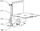
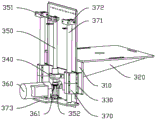
Referring to fig. 6-9, the discharging mechanism 300 comprises a lifting seat plate 310, a screw nut 340 and a speed reducing motor 360; the front side of the lifting seat plate 310 is provided with a rubber plate support plate 320 in an arrangement way, and the rear side of the lifting seat plate 310 is provided with a mounting plate 330; the lead screw nut 340 is fixed in the center of the mounting plate 330, the lead screw nut 340 is fixed, the lifting lead screw 350 is arranged on the lead screw nut 340, the top of the lifting lead screw 350 is connected with the rack 100 through a connecting seat bearing 351, and the bottom of the lifting lead screw 350 is provided with a driven bevel gear 352; the driving bevel gear 361 meshed with the driven bevel gear 352 is installed on the speed reducing motor 360, the speed reducing motor 360 drives the driven bevel gear 352 through the driving bevel gear 361, the lifting screw 350 rotates, and the lifting base plate 310 is lifted on the lifting screw 350 through the screw nut 340 so as to adjust the lifting of the rubber plate support plate 320.
In order to ensure the stability of lifting, the linear bearings 370 on the two sides of the screw nut 340 are installed on the installation plate 330, the guide rods 371 are installed on the linear bearings 370, the tops of the guide rods 371 are connected with the machine frame 100 through the axle seat 372, the bottom of the guide rods 371 is fixed with a bottom plate 373, and the bottom plate 373 is connected with the speed reduction motor 360.
Referring to fig. 10, the suction plate mechanism 400 includes a mounting platen 410, a lifting cylinder 420, a connecting rod 430, a suction rod arm 440, a suction rod 450; the upper part of the installation bedplate 410 is connected with the linear guide rail assembly 500; the lifting cylinder 420 is fixed on the installation bedplate 410, and a piston rod of the lifting cylinder 420 penetrates through the installation bedplate 410 and extends to the lower part of the installation bedplate; the connecting rod 430 is arranged below the installation bedplate 410, is connected with a piston rod of the lifting cylinder 420, and pushes the connecting rod 430 downwards through the lifting cylinder 420; the suction rod arms 440 are arranged on the connecting rods 430 and are perpendicular to the connecting rods 430; the suction rod 450 is arranged to be mounted on the suction rod arm 440, and during the downward movement of the connection rod 430, the suction rod 450 of the suction rod arm 440 is pressed toward the circuit board.
The linear guide rail assembly 500 includes a linear motor 510, a slide rail 520; the linear motor 510 is provided with a sliding platen 511; the slide rail 520 is arranged in parallel with the linear motor 510, a slide block 521 is arranged on the slide rail 520, a slide plate 530 is arranged between the slide block 521 and the slide bedplate 511, and the slide plate 530 is connected with the installation bedplate 410 through an upright 540.
In order to conveniently move the circuit board, the mobile trolley 380 is further included, the L-shaped supporting rods 381 are arranged on the mobile trolley 380 in an arrayed mode, when the mobile trolley 380 is pushed in, the rubber plate supporting plate 320 is inserted between the L-shaped supporting rods 381, and the circuit board is placed on the L-shaped supporting rods 381.
The embodiments of the present invention have been described in detail with reference to the accompanying drawings, but the present invention is not limited to the above embodiments, and various changes can be made within the knowledge of those skilled in the art without departing from the gist of the present invention.
Claims (8)
1. The utility model provides a multifunctional platform for detecting machine which characterized in that includes:
the device comprises a rack (100), wherein the working area of the rack (100) is divided into a conveying area (110) and at least two material placing areas (120);
a conveying mechanism (200), the conveying mechanism (200) being disposed within the conveying zone (110);
the discharging mechanism (300), the discharging mechanism (300) is arranged in the discharging area (120);
the suction plate mechanism (400), the suction plate mechanism (400) is arranged on the linear guide rail assembly (500), the linear guide rail assembly (500) is fixed on the rack (100), and the suction plate mechanism (400) adsorbs, grabs and places the materials on the conveying mechanism (200) on the discharging mechanism (300).
2. The multifunctional platform for testing machines according to claim 1, characterized in that said conveying means (200) comprise:
the conveying roller set (210) is formed by arranging a plurality of conveying rubber rollers (211) in parallel, and the conveying rubber rollers (211) are connected in series and driven by a first servo motor (212);
the conveying baffle (220) is positioned in the rear area of the conveying roller group (210) and arranged between the conveying rubber rollers (211);
a correcting cleat assembly (230), the correcting cleat assembly (230) located at a front region of the set of conveyor rollers (210).
3. The multifunctional platform for testing machines of claim 2, wherein said alignment cleat assembly (230) comprises:
the correcting clamp plate (231), the correcting clamp plate (231) is divided into a left correcting clamp plate (2311) and a right correcting clamp plate (2312), and the left correcting clamp plate (2311) and the right correcting clamp plate (2312) are respectively positioned at the left side and the right side of the conveying baffle plate (220);
the left fixing seat plate (232) is used for fixedly mounting the left correcting splint (2311), and two left bearing sliding seats (2321) are mounted at the bottom of the left fixing seat plate (232);
the right fixing seat plate (233), the right fixing seat plate (233) is used for fixedly installing the right correcting splint (2312), and two right bearing sliding seats (2331) are arranged at the bottom of the right fixing seat plate (233);
the guide rods (234) are respectively inserted into the left bearing sliding seat (2321) and the right bearing sliding seat (2331);
the transmission belt pulley (235), two transmission belt pulleys (235) are adopted, a transmission belt ring (236) is installed between the transmission belt pulleys (235), and the front section and the rear section of the transmission belt ring (236) are respectively connected with the left bearing sliding seat (2321) and the right bearing sliding seat (2331).
4. The multifunctional platform for the detecting machine as claimed in claim 1, wherein the discharging mechanism (300) comprises:
the lifting seat plate (310), the front side of the lifting seat plate (310) is provided with rubber plate support plates (320), and the rear side of the lifting seat plate (310) is provided with a mounting plate (330);
the lead screw nut (340), the lead screw nut (340) is fixed in the center of the mounting plate (330), a lifting lead screw (350) is installed on the lead screw nut (340), the top of the lifting lead screw (350) is connected with the rack (100) through a connecting seat bearing (351), and a driven bevel gear (352) is installed at the bottom of the lifting lead screw (350);
and the speed reducing motor (360) is provided with a driving bevel gear (361) meshed with the driven bevel gear (352).
5. The multifunctional platform for the inspection machine according to claim 4, wherein the mounting plate (330) is provided with linear bearings (370) at two sides of the lead screw nut (340), the linear bearings (370) are provided with guide rods (371), the tops of the guide rods (371) are connected with the frame (100) through axle center seats (372), the bottoms of the guide rods (371) are fixed with bottom plates (373), and the bottom plates (373) are connected with the speed reduction motor (360).
6. The multifunctional platform for testing machines according to claim 1, characterized in that said suction plate mechanism (400) comprises:
the mounting bedplate (410) is connected with the linear guide rail assembly (500) above the mounting bedplate (410);
the lifting cylinder (420) is fixed on the installation bedplate (410), and a piston rod of the lifting cylinder (420) penetrates through the installation bedplate (410) to extend to the lower part of the installation bedplate (410);
the connecting rod (430), the said connecting rod (430) is fixed to the said installation platen (410) below, and connect with piston rod of the said lifting cylinder (420);
the suction rod arms (440) are arranged on the connecting rod (430) and are perpendicular to the connecting rod (430);
a suction rod (450), wherein the suction rod (450) is arranged and installed on the suction rod arm (440).
7. The multifunctional platform for testing machines of claim 6, wherein said linear guide assembly (500) comprises:
the linear motor (510), the said linear motor (510) is equipped with the sliding platen (511);
the sliding rail (520) is arranged in parallel with the linear motor (510), a sliding block (521) is arranged on the sliding rail (520), a sliding plate (530) is arranged between the sliding block (521) and the sliding bedplate (511), and the sliding plate (530) is connected with the mounting bedplate (410) through a vertical rod (540).
8. The multifunctional platform for the detecting machine as claimed in claim 4, further comprising a moving trolley (380), wherein L-shaped supporting rods (381) are arranged on the moving trolley (380), and the rubber plate supporting plate (320) is inserted between the L-shaped supporting rods (381) when the moving trolley (380) is pushed in.
Priority Applications (1)
| Application Number | Priority Date | Filing Date | Title |
|---|---|---|---|
| CN202020974664.9U CN212831474U (en) | 2020-06-01 | 2020-06-01 | Multifunctional platform for detecting machine |
Applications Claiming Priority (1)
| Application Number | Priority Date | Filing Date | Title |
|---|---|---|---|
| CN202020974664.9U CN212831474U (en) | 2020-06-01 | 2020-06-01 | Multifunctional platform for detecting machine |
Publications (1)
| Publication Number | Publication Date |
|---|---|
| CN212831474U true CN212831474U (en) | 2021-03-30 |
Family
ID=75169907
Family Applications (1)
| Application Number | Title | Priority Date | Filing Date |
|---|---|---|---|
| CN202020974664.9U Active CN212831474U (en) | 2020-06-01 | 2020-06-01 | Multifunctional platform for detecting machine |
Country Status (1)
| Country | Link |
|---|---|
| CN (1) | CN212831474U (en) |
Cited By (1)
| Publication number | Priority date | Publication date | Assignee | Title |
|---|---|---|---|---|
| CN116078683A (en) * | 2022-11-21 | 2023-05-09 | 浙江柳市线路板有限公司 | Circuit board detection equipment |
-
2020
- 2020-06-01 CN CN202020974664.9U patent/CN212831474U/en active Active
Cited By (2)
| Publication number | Priority date | Publication date | Assignee | Title |
|---|---|---|---|---|
| CN116078683A (en) * | 2022-11-21 | 2023-05-09 | 浙江柳市线路板有限公司 | Circuit board detection equipment |
| CN116078683B (en) * | 2022-11-21 | 2023-11-07 | 浙江柳市线路板有限公司 | Circuit board detection equipment |
Similar Documents
| Publication | Publication Date | Title |
|---|---|---|
| CN110404800B (en) | Printed circuit board detection equipment and printed circuit board detection method | |
| CN107413979B (en) | Feeding mechanism of metal plate flanging machine | |
| CN110695233A (en) | Middle-layer stamping production line of electric cooker | |
| CN212831474U (en) | Multifunctional platform for detecting machine | |
| CN113998429A (en) | Automatic feeding equipment of PCB (printed circuit board) drilling machine | |
| CN113526114A (en) | Full-automatic feeding and visual detection device | |
| CN212831709U (en) | Plate placing machine | |
| CN110697393A (en) | Double fungus basket machine of putting on shelf | |
| KR100339499B1 (en) | Loadding device and method of PCB manufacturing process | |
| CN116100092B (en) | Automatic feeding and discharging equipment for gear milling machine | |
| CN212821236U (en) | Take copper layer thickness to detect function and put trigger | |
| CN112027681A (en) | Automatic change panel pile up neatly device | |
| CN111337999A (en) | Automatic attack tooth check out test set | |
| CN215700072U (en) | Plate conveying device of plate tooth-jointing machine | |
| CN216117375U (en) | Chip support optical detection equipment | |
| CN215401566U (en) | Plate hot-pressing production line | |
| CN114873272A (en) | Continuous overturning feeding device, feeding equipment and sorting system | |
| CN215236017U (en) | Automatic detection device for surface defects of steel bar | |
| CN214291194U (en) | Accompany plating plate surface copper foil and retrieve assembly line | |
| CN212831475U (en) | Board collecting machine for browned circuit board | |
| CN215236018U (en) | Novel rod iron detects and selects separately device | |
| CN219708203U (en) | Material transfer device | |
| CN217064462U (en) | Printed circuit board paster defect detection device | |
| CN216037189U (en) | Automatic conveying and detecting device for steel bars | |
| CN214828691U (en) | Plate conveyer |
Legal Events
| Date | Code | Title | Description |
|---|---|---|---|
| GR01 | Patent grant | ||
| GR01 | Patent grant |