CN212526280U - Heavy automatic feeding single-end saw - Google Patents
Heavy automatic feeding single-end saw Download PDFInfo
- Publication number
- CN212526280U CN212526280U CN202021288476.7U CN202021288476U CN212526280U CN 212526280 U CN212526280 U CN 212526280U CN 202021288476 U CN202021288476 U CN 202021288476U CN 212526280 U CN212526280 U CN 212526280U
- Authority
- CN
- China
- Prior art keywords
- fixed
- plate
- saw
- guide rail
- supporting plate
- Prior art date
- Legal status (The legal status is an assumption and is not a legal conclusion. Google has not performed a legal analysis and makes no representation as to the accuracy of the status listed.)
- Active
Links
- 239000000463 material Substances 0.000 claims abstract description 42
- 238000003825 pressing Methods 0.000 claims description 21
- 229910052782 aluminium Inorganic materials 0.000 abstract description 22
- XAGFODPZIPBFFR-UHFFFAOYSA-N aluminium Chemical compound [Al] XAGFODPZIPBFFR-UHFFFAOYSA-N 0.000 abstract description 22
- 229910000838 Al alloy Inorganic materials 0.000 abstract description 13
- 230000000694 effects Effects 0.000 description 2
- 238000000926 separation method Methods 0.000 description 2
- 238000012546 transfer Methods 0.000 description 2
- 230000009286 beneficial effect Effects 0.000 description 1
- 238000013461 design Methods 0.000 description 1
- 238000007723 die pressing method Methods 0.000 description 1
- 229910052751 metal Inorganic materials 0.000 description 1
- 239000002184 metal Substances 0.000 description 1
- 238000000034 method Methods 0.000 description 1
- 238000012986 modification Methods 0.000 description 1
- 230000004048 modification Effects 0.000 description 1
- 230000011218 segmentation Effects 0.000 description 1
- 238000006467 substitution reaction Methods 0.000 description 1
- 238000013519 translation Methods 0.000 description 1
Images


Abstract
The utility model relates to the technical field of aluminum profile cutting, in particular to a heavy automatic feeding single-end saw, which comprises a conveying frame, one end part of the conveying frame is provided with a cutting saw connected with a feeding platform, a material distributing platform is fixed on the outer side of the cutting saw, the conveying frame is provided with a feeding platform, a side plate is vertically fixed on one side of the material distributing platform, the upper end and the lower end of the side plate are fixed with a first guide rail, the left side and the right side of the material distributing platform are fixed with a second guide rail, the first guide rail and the second guide rail are both perpendicular to the cutting saw, the outer side of the first guide rail is connected with a material distributing backup plate through a slider, the upper side of the second guide rail is connected with a supporting plate through a slider; the utility model discloses can solve prior art's autoloading cutting device effectively and cut off the back with the aluminium alloy through the saw bit, the saw bit easily takes place friction and little collision with the incision section when moving back the sword, leads to the problem of the incision unevenness of aluminium alloy.
Description
Technical Field
The utility model relates to an aluminium alloy cutting technical field, concretely relates to heavy automatic material conveying single-end saw.
Background
The section bar is widely applied to industrial buildings and metal structures as a material, and in order to conveniently realize the concentrated cutting segmentation of a plurality of long aluminum section bars, the automatic aluminum section cutting machine specially used for aluminum section bar cutting is designed in the prior art.
The aluminum product automatic feeding and cutting device in the prior art mainly comprises an automatic feeding system and a cutting system, wherein the automatic feeding system is used for automatically feeding materials. The cutting system mainly comprises a saw blade, a spindle motor for driving the saw blade to rotate, a pneumatic cylinder or a direct-acting module and a linear guide rail. The spindle motor is arranged on the linear guide rail through the precision slide block and is pushed by the pneumatic hydraulic cylinder or the direct-acting module to move back and forth from inside to outside to realize cutting.
But aluminum product autoloading cutting device among the prior art is cutting off the back through the saw bit with the aluminium alloy, and the cooperation directly moves the reseing of module, and the saw bit is when moving back the sword, because the aluminium alloy that is cut off is still fixed on the branch material bench by the centre gripping, and the saw bit is pressed close to its cut section, easily the cut section takes place friction and little collision when the saw bit moves back the sword, leads to the cut unevenness of aluminium alloy.
SUMMERY OF THE UTILITY MODEL
Solves the technical problem
To the above-mentioned shortcoming that prior art exists, the utility model provides a heavy automatic feeding single-end saw can solve prior art's autoloading cutting device effectively and cut off the back with the aluminium alloy through the saw bit, and the saw bit easily takes place friction and little collision with the incision section when moving back the sword, leads to the problem of the incision unevenness of aluminium alloy.
Technical scheme
In order to achieve the above purpose, the utility model discloses a following technical scheme realizes:
a heavy type automatic feeding single-end saw comprises a conveying frame, wherein a cutting saw connected with a feeding platform is arranged at one end of the conveying frame, a material distributing table is fixed on the outer side of the cutting saw, a feeding platform is arranged on the conveying frame, the feeding platform reciprocates on the conveying frame through a direct-acting module, a front clamp body is fixed on the feeding platform, and a rear clamp body is arranged at a position, close to the cutting saw, of the conveying frame; a side plate is vertically fixed on one side of the material distribution table, first guide rails are fixed at the upper end and the lower end of the side plate, second guide rails are fixed on the left side and the right side of the material distribution table, the first guide rails and the second guide rails are perpendicular to the cutting saw, a material distribution backup plate is connected to the outer side of the first guide rails through sliding blocks, a supporting plate is connected to the upper side of the second guide rails through sliding blocks, the material distribution backup plate and the supporting plate are vertically fixed together, and a material distribution cylinder is fixed at the bottom of the supporting plate; the front clamp body and the rear clamp body respectively comprise a pair of support frames which are arranged in parallel, a pressing cylinder is connected onto each support frame, a pressing plate is fixed onto a piston rod of each pressing cylinder, and one support frame of the rear clamp body is fixed onto the supporting plate.
Furthermore, the direct-acting module comprises a servo motor, a roller lead screw and a third guide rail, the third guide rail is fixed on two sides of the conveying frame, the roller lead screw is parallel to the third guide rail and is rotatably connected to two ends of the conveying frame, the servo motor is linked with the roller lead screw, two sides of the bottom of the feeding platform are connected with the third guide rail through a sliding block, and the middle of the feeding platform is fixedly connected with a moving pair of the roller lead screw.
Furthermore, the support frame comprises a supporting plate and a stand column, the supporting plate and the conveying frame are arranged in parallel and are fixed through the stand column, the lower air cylinder is fixed on the supporting plate, a piston rod of the lower air cylinder penetrates through the supporting plate and is fixed with the lower pressing plate, the supporting plate is provided with a guide hole in the lower air cylinder, a guide pillar is arranged in the guide hole in a sliding mode, and the lower end of the guide pillar is fixedly connected to the supporting plate.
Furthermore, one end of the support frame, which is close to the cutting saw, is provided with a side clamping plate, the side clamping plate is parallel to the material distribution backup plate, and a side clamping cylinder is fixed on the rear side of the side clamping plate.
Furthermore, the supporting plate is provided with a clamping piece perpendicular to the material distribution backup plate.
Furthermore, the clamping piece comprises an L-shaped clamping plate, a clamping cylinder and a fourth guide rail, the fourth guide rail is fixed on a supporting plate of the rear clamping body and is perpendicular to the material distribution backup plate, the upper portion of the L-shaped clamping plate is connected onto the fourth guide rail in a sliding mode through a sliding block, and the lower portion of the L-shaped clamping plate is connected with the clamping cylinder.
Furthermore, the other end of the conveying frame is provided with a bracket, and the bracket comprises a frame, and a plurality of rollers are rotatably connected to the frame.
Advantageous effects
Adopt the utility model provides a technical scheme compares with known public technique, has following beneficial effect:
1. the utility model discloses an increase the branch material backup plate and the layer board of connecting in order to remove at the branch material bench, divide a separation unit that a die-pressing cylinder constitutes of material cylinder and back clamp, can accomplish the back to the cutting of aluminium alloy at the slitting saw, when preparing to move back the sword, aluminium alloy after will cutting off through the separation unit who adds releases one section distance to the outside, make its incision keep away from the slitting saw, thereby prevent effectively that the slitting saw from taking place friction and little collision with the incision section when moving back the sword, with the incision of protection aluminium alloy is level and smooth.
Drawings
In order to more clearly illustrate the embodiments of the present invention or the technical solutions in the prior art, the drawings used in the description of the embodiments or the prior art will be briefly described below. It is obvious that the drawings in the following description are only some embodiments of the invention, and that for a person skilled in the art, other drawings can be derived from them without inventive effort.
FIG. 1 is a front schematic view of the overall structure of the automatic feeding single-end saw of the present invention;
FIG. 2 is a rear view of the overall structure of the automatic feeding single-end saw of the present invention;
FIG. 3 is a schematic view of the connection on the material distributing table of the present invention;
FIG. 4 is a rear view of the feeding platform and the distributing platform of the present invention;
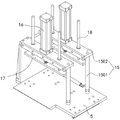
FIG. 5 is a perspective view of the front clamp body of the present invention;
the reference numerals in the drawings denote: 1-a transfer rack; 2-a feeding platform; 3-cutting saw; 4-a material distribution table; 5-a feeding platform; 6-a direct-acting module; 7-front clamp body; 8-rear clamp body; 9-side plate; 10-a first guide rail; 11-a second guide rail; 12-a material separating backup plate; 13-a pallet; 14-a material separating cylinder; 15-a support frame; 16-a down-pressure cylinder; 17-a lower platen; 18-a guide post; 19-side clamping plate; 20-side clamping cylinder; 21-L shaped splints; 22-a clamping cylinder; 23-a fourth guide rail; 24-a bracket; 601-a servo motor; 602-a roller screw; 603-a third guide rail; 1501-bracing plates; 1502-column; 2401-a frame; 2402-roller.
Detailed Description
In order to make the objects, technical solutions and advantages of the embodiments of the present invention clearer, the drawings in the embodiments of the present invention are combined below to clearly and completely describe the technical solutions in the embodiments of the present invention. It is to be understood that the embodiments described are only some of the embodiments of the present invention, and not all of them. Based on the embodiments in the present invention, all other embodiments obtained by a person skilled in the art without creative efforts belong to the protection scope of the present invention.
The present invention will be further described with reference to the following examples.
Examples
The heavy automatic feeding single-end saw of this embodiment, refer to fig. 1-2, including conveying frame 1, a tip of conveying frame 1 is equipped with slitting saw 3 of connecting feeding platform 2, slitting saw 3's the outside is fixed with branch material platform 4, be equipped with feeding platform 5 on the conveying frame 1, feeding platform 5 is through directly moving module 6 reciprocating motion on conveying frame 1, wherein, feeding platform 2 of slitting saw 3 is used for dragging slitting saw 3 and drives slitting saw 3 pivoted spindle motor and advance and retreat, realize slitting saw 3's cutting and withdraw of sword, it does not do not describe herein for prior art again.
The direct-acting module 6 comprises a servo motor 601, a roller screw 602 and a third guide rail 603, the third guide rail 603 is fixed on two sides of the conveying frame 1, the roller screw 602 is parallel to the third guide rail 603 and is rotatably connected to two ends of the conveying frame 1, the servo motor 601 is linked with the roller screw 602, two sides of the bottom of the feeding platform 5 are connected with the third guide rail 603 through a slider, and the middle of the bottom of the feeding platform is fixedly connected with a moving pair of the roller screw 602. The aluminum profile is continuously fed to one side of the cutting saw 3 through the feeding platform 5.
Referring to fig. 5, a front clamp 7 is fixed on the feeding platform 5, a rear clamp 8 is arranged at a position, close to the dicing saw 3, of the conveying frame 1, the front clamp 7 and the rear clamp 8 are respectively used for clamping and fixing an aluminum profile placed on the feeding platform 5, and the feeding distance of the aluminum profile is relatively accurate. The front clamp body 7 and the rear clamp body 8 both comprise a pair of support frames 15 which are arranged in parallel, a lower pressure cylinder 16 is connected onto the support frames 15, and a lower pressure plate 17 is fixed on a piston rod of the lower pressure cylinder 16. When the aluminum profile clamping device is used, the lower pressing plate 17 is driven to move downwards through the lower pressing air cylinder 16 to clamp and fix an aluminum profile.
Referring to fig. 3-4, a support frame 15 of the rear clamp body 8 on the outer side is fixed on the support plate 13.
A side plate 9 is vertically fixed on one side of the material distribution table 4, first guide rails 10 are fixed at the upper end and the lower end of the side plate 9, second guide rails 11 are fixed on the left side and the right side of the material distribution table 4, the first guide rails 10 and the second guide rails 11 are both perpendicular to the cutting saw 3, the outer side of the first guide rails 10 is connected with a material distribution backup plate 12 through sliding blocks, the upper side of the second guide rails 11 is connected with a supporting plate 13 through sliding blocks, the material distribution backup plate 12 and the supporting plate 13 are vertically fixed together, and a material distribution cylinder 14 is fixed at the bottom of the;
referring to fig. 5, the supporting frame 15 includes a supporting plate 1501 and a vertical column 1502, the supporting plate 1501 is parallel to the conveying frame 1, and is fixed through the vertical column 1502, the down-pressing cylinder 16 is fixed on the supporting plate 1501, a piston rod of the down-pressing cylinder 16 penetrates through the supporting plate 1501 and is fixed with a down-pressing plate 17, the supporting plate 1501 is provided with a guide hole in the down-pressing cylinder 16, a guide pillar 18 is slidably arranged in the guide hole, and the lower end of the guide pillar 18 is fixedly connected to the supporting plate 1501. The guide post 18 is added, so that the descending stability of the lower pressing plate 17 is better.
The present embodiment preferably has a side clamp plate 19 on the supporting frame 15 near one end of the cutting saw 3, the side clamp plate 19 is parallel to the separating backup plate 12, and a side clamp cylinder 20 is fixed on the rear side of the side clamp plate 19. The aluminum profile is clamped between the side clamping plate 19 and the material distribution backup plate 12 through the side clamping plate 19 and the side clamping cylinder 20, so that clamping and fixing in the horizontal direction are realized, and smooth cutting of the cutting saw 3 is facilitated.
Referring to fig. 3, the supporting plate 13 is provided with a clamping piece perpendicular to the material separating backup plate 12. The clamping piece comprises an L-shaped clamping plate 21, a clamping cylinder 22 and a fourth guide rail 23, the fourth guide rail 23 is fixed on a supporting plate 1501 of the rear clamping body 8 and is perpendicular to the material distribution backup plate 12, the upper portion of the L-shaped clamping plate 21 is connected to the fourth guide rail 23 in a sliding mode through a sliding block, and the lower portion of the L-shaped clamping plate is connected with the clamping cylinder 22. The design of the clamping piece can be matched with the side clamping plate 19 to further clamp and fix the aluminum profile in the horizontal direction during cutting.
Meanwhile, the aluminum profile cutting device can be matched with a pressing cylinder 16 arranged on the supporting plate 13 to further clamp and fix the cut aluminum profile in the horizontal direction, so that the cut aluminum profile is ensured to be smoothly separated.
Referring to fig. 24, a bracket 24 is provided at the other end of the transfer rack 1, and the bracket 24 includes a rack 2401, and a plurality of rollers 2402 are rotatably coupled to the rack 2401. The brackets 24 are used to support the longer aluminum profiles.
When the aluminum profile feeding device is used, the aluminum profile is clamped and fixed on the feeding platform 5 through the front clamp 7, and the feeding platform 5 finishes feeding of the aluminum profile through translation of the linear motion module 6; then the downward pressing cylinder 16 of the front clamp 7 is lifted, the side clamping plates 19 and the clamping pieces position and clamp the aluminum profile in the horizontal direction, and then the downward pressing cylinders 16 of the front clamp 7 and the rear clamp 8 move downwards to fix the aluminum profile in the vertical direction; the fixed back slitting saw 3 cuts off the operation under the effect of feeding platform 2, and after the cutting is accomplished, when preparing to move back the sword, divide material cylinder 14 action, will centre gripping between dividing material backup plate 12 and layer board 13, the aluminium alloy after being cut off pushes out a section distance to the outside to make its incision keep away from slitting saw 3 to prevent effectively that slitting saw 3 from taking place friction and little collision with the incision section when moving back the sword, in order to protect the incision of aluminium alloy to level.
The above embodiments are only used to illustrate the technical solution of the present invention, and not to limit it; although the present invention has been described in detail with reference to the foregoing embodiments, it should be understood by those skilled in the art that: the technical solutions described in the foregoing embodiments may still be modified, or some technical features may be equivalently replaced; such modifications and substitutions do not depart from the spirit and scope of the present invention in its corresponding aspects.
Claims (7)
1. A heavy automatic feeding single-end saw comprises a conveying frame, wherein a cutting saw connected with a feeding platform is arranged at one end of the conveying frame, and a material distributing table is fixed on the outer side of the cutting saw;
a side plate is vertically fixed on one side of the material distribution table, first guide rails are fixed at the upper end and the lower end of the side plate, second guide rails are fixed on the left side and the right side of the material distribution table, the first guide rails and the second guide rails are perpendicular to the cutting saw, a material distribution backup plate is connected to the outer side of the first guide rails through sliding blocks, a supporting plate is connected to the upper side of the second guide rails through sliding blocks, the material distribution backup plate and the supporting plate are vertically fixed together, and a material distribution cylinder is fixed at the bottom of the supporting plate;
the front clamp body and the rear clamp body respectively comprise a pair of support frames which are arranged in parallel, a pressing cylinder is connected onto each support frame, a pressing plate is fixed onto a piston rod of each pressing cylinder, and one support frame of the rear clamp body is fixed onto the supporting plate.
2. The heavy-duty automatic feeding single-end saw as claimed in claim 1, wherein the direct-acting module comprises a servo motor, a roller lead screw and a third guide rail, the third guide rail is fixed on two sides of the conveying frame, the roller lead screw is arranged in parallel with the third guide rail and is rotatably connected to two ends of the conveying frame, the servo motor is linked with the roller lead screw, two sides of the bottom of the feeding platform are connected with the third guide rail through a sliding block, and the middle of the feeding platform is fixedly connected with a moving pair of the roller lead screw.
3. The heavy-duty automatic feeding single-end saw according to claim 1, wherein the supporting frame comprises a supporting plate and a column, the supporting plate is arranged in parallel with the conveying frame and fixed by the column, the lower pressing cylinder is fixed on the supporting plate, a piston rod of the lower pressing cylinder penetrates through the supporting plate to be fixed with the lower pressing plate, the supporting plate is provided with a guide hole in the lower pressing cylinder, a guide post is slidably arranged in the guide hole, and the lower end of the guide post is fixedly connected to the supporting plate.
4. The heavy-duty automatic feeding single-end saw as claimed in claim 1, wherein a side clamping plate is provided on one end of the supporting frame near the cutting saw, the side clamping plate is parallel to the material separating backup plate, and a side clamping cylinder is fixed on the rear side of the side clamping plate.
5. The heavy duty automatic feed single end saw as claimed in claim 1, wherein said blade is provided with a clamp perpendicular to said feed fence.
6. The heavy-duty automatic feeding single-end saw according to claim 5, wherein said clamping member comprises an L-shaped clamping plate, a clamping cylinder and a fourth guide rail, said fourth guide rail is fixed on a supporting plate of the rear clamping body and is perpendicular to the material-dividing backup plate, the upper portion of said L-shaped clamping plate is slidably connected to said fourth guide rail through a sliding block, and the lower portion of said L-shaped clamping plate is connected to said clamping cylinder.
7. The heavy duty automatic feed single end saw as claimed in claim 1, wherein said carriage is provided at the other end with a bracket, said bracket including a frame, said frame having a plurality of rollers rotatably connected thereto.
Priority Applications (1)
| Application Number | Priority Date | Filing Date | Title |
|---|---|---|---|
| CN202021288476.7U CN212526280U (en) | 2020-07-06 | 2020-07-06 | Heavy automatic feeding single-end saw |
Applications Claiming Priority (1)
| Application Number | Priority Date | Filing Date | Title |
|---|---|---|---|
| CN202021288476.7U CN212526280U (en) | 2020-07-06 | 2020-07-06 | Heavy automatic feeding single-end saw |
Publications (1)
| Publication Number | Publication Date |
|---|---|
| CN212526280U true CN212526280U (en) | 2021-02-12 |
Family
ID=74521875
Family Applications (1)
| Application Number | Title | Priority Date | Filing Date |
|---|---|---|---|
| CN202021288476.7U Active CN212526280U (en) | 2020-07-06 | 2020-07-06 | Heavy automatic feeding single-end saw |
Country Status (1)
| Country | Link |
|---|---|
| CN (1) | CN212526280U (en) |
-
2020
- 2020-07-06 CN CN202021288476.7U patent/CN212526280U/en active Active
Similar Documents
| Publication | Publication Date | Title |
|---|---|---|
| CN102390063B (en) | Back loading high-speed computer panel saw | |
| CN202367813U (en) | After-loading high-speed computer cut-to-size saw | |
| CN101549501B (en) | Plate right-angle cutting machine | |
| CN111452116A (en) | Plate fixed-length cutting device of composite plate production line | |
| CN110695448B (en) | Plastic-aluminum section bar saw cuts equipment | |
| CN212526280U (en) | Heavy automatic feeding single-end saw | |
| CN212123503U (en) | Precise cutting machine | |
| CN210146675U (en) | 1000T pure electric three-head tractor | |
| CN218050863U (en) | Tube plate laser cutting all-in-one machine | |
| CN211438385U (en) | Conveying type steel belt shearing machine | |
| CN205148467U (en) | Equipment is saw cut to section bar abnormal shape | |
| CN210589739U (en) | Wood floor cutting machine | |
| CN210632675U (en) | 1250T double-hydraulic full-automatic three-head tractor | |
| CN210551886U (en) | Workstation and processing equipment of wood moulding processing equipment | |
| CN113510290A (en) | Steel cutting equipment with accurate cutting function and operation method thereof | |
| CN210755527U (en) | Sawing processing line for aluminum-plastic section bar | |
| CN209936013U (en) | Cutting platform for aluminum profile interrupted saw | |
| CN217666866U (en) | Band sawing machine | |
| CN214920975U (en) | Cutting device for aluminum product processing | |
| CN214489793U (en) | Positioning device for cutting of scraper | |
| CN217531141U (en) | High-efficient thick bamboo tube cutting machine | |
| CN218285776U (en) | Profiled bar cutting machine | |
| CN217991773U (en) | Section bar splicing machine | |
| CN216634732U (en) | Log cutting device | |
| CN220196516U (en) | Plate cutting machine with good stability |
Legal Events
| Date | Code | Title | Description |
|---|---|---|---|
| GR01 | Patent grant | ||
| GR01 | Patent grant | ||
| PE01 | Entry into force of the registration of the contract for pledge of patent right |
Denomination of utility model: Heavy duty automatic feeding single head saw Effective date of registration: 20231011 Granted publication date: 20210212 Pledgee: Ronggui sub branch of Guangdong Shunde Rural Commercial Bank Co.,Ltd. Pledgor: SHUNDE KINGTOOL ALUMINUM DOORS AND WINDOWS MACHINERY Co.,Ltd. Registration number: Y2023980060683 |
|
| PE01 | Entry into force of the registration of the contract for pledge of patent right |