CN212426873U - Flooding-proof drainage landscape support system - Google Patents
Flooding-proof drainage landscape support system Download PDFInfo
- Publication number
- CN212426873U CN212426873U CN202022044776.7U CN202022044776U CN212426873U CN 212426873 U CN212426873 U CN 212426873U CN 202022044776 U CN202022044776 U CN 202022044776U CN 212426873 U CN212426873 U CN 212426873U
- Authority
- CN
- China
- Prior art keywords
- base body
- groove
- proof
- pipe
- flooding
- Prior art date
- Legal status (The legal status is an assumption and is not a legal conclusion. Google has not performed a legal analysis and makes no representation as to the accuracy of the status listed.)
- Expired - Fee Related
Links
Images


Classifications
-
- Y—GENERAL TAGGING OF NEW TECHNOLOGICAL DEVELOPMENTS; GENERAL TAGGING OF CROSS-SECTIONAL TECHNOLOGIES SPANNING OVER SEVERAL SECTIONS OF THE IPC; TECHNICAL SUBJECTS COVERED BY FORMER USPC CROSS-REFERENCE ART COLLECTIONS [XRACs] AND DIGESTS
- Y02—TECHNOLOGIES OR APPLICATIONS FOR MITIGATION OR ADAPTATION AGAINST CLIMATE CHANGE
- Y02A—TECHNOLOGIES FOR ADAPTATION TO CLIMATE CHANGE
- Y02A30/00—Adapting or protecting infrastructure or their operation
- Y02A30/60—Planning or developing urban green infrastructure
Abstract
The utility model provides a prevent flooding drainage view support system, belongs to traffic and city municipal facilities technical field, includes and prevents flooding hard shoulder unit, a plurality of prevent flooding hard shoulder connector, goes up to constitute the base member, constitutes the base member etc. down, prevent flooding hard shoulder unit by last constitution base member, constitute the base member combination down and form, set up the upper substrate recess between upper substrate middle part protruding end and the upper substrate limit portion protruding end, the lower extreme of upper substrate middle part protruding end and the upper end of upper substrate recess set up the upper substrate semicircle notch that runs through respectively, in constituting the base member down, the top is equipped with two lower base member protruding ends, set up lower base member middle part recess between two lower base member protruding ends, the outside of lower base member protruding end sets up lower substrate limit portion recess etc.. The utility model discloses can dredge fast, the high-efficient discharge too much ponding on the road surface effectively, effectively play the flood control effect of preventing flooding, it is very important to reach the control runoff through building hard shoulder and municipal drainage road system of combining together and store up and prevent flooding flood control effect.
Description
Technical Field
The utility model belongs to the technical field of traffic and city municipal facilities, especially, relate to a flood control drainage view support system.
Background
The hard road isolation pier is an important traffic facility, mainly plays the effect of isolation and protection, is used for injecing the area that traveles or parks of car, and at present, hard road isolation pier sets up mainly in the position that easily takes place vehicle and the fixed facilities in the way and bump on highway and urban road, for example: the road corner, the entrances and exits of the posts, toll stations and elevated roads in the road, parking lots, communities, gardens, gas stations and the like play a role in isolation, traffic accidents are prevented, the smoothness of traffic can be kept, the construction of highway infrastructure can be rapidly developed along with the development of economy, in recent years, along with the development of highway construction career, the application and the variety of isolation facilities are greatly developed, and the isolation facilities increasingly show the important role in traffic safety and environmental protection, besides, the existing isolation piers only have the isolation function, so that the isolation piers have single function and cannot meet the requirements of people on environmental greening, green plants can not only beautify the environment, purify the air, reduce the noise and reduce the heat island effect, but also release a large amount of oxygen, and are closely related to the life of people; along with the rapid development of cities, high-rise buildings and roads are continuously increased, green plants are gradually reduced, the greening area is increased, the cities are beautified, and the urban environment is very important to improve. The road surface, street are laid and are all adopted cement, asphalt and floor bricks at present, the water permeability is extremely poor, when raining, the road often flows along the road, flows along the street instead of flowing along the green land, and the isolation pier is the important factor in urban traffic planning, so that the effects of controlling runoff storage and flood control by building an isolation pier and municipal drainage road combined system are very important.
SUMMERY OF THE UTILITY MODEL
In order to solve the technical problem that exists, the utility model provides a flood control drainage view support system, the utility model discloses flood control drainage view support system not only can play isolation and guard action, can satisfy people to the environmental greening demand moreover, can dredge fast, high-efficient discharge too much ponding on the road surface effectively, effectively play flood control effect, combine together the system through construction hard shoulder and municipal drainage road and reach the control runoff and store up and flood control effect very important.
In order to realize the purpose, the utility model discloses a technical scheme be:
a flood-proof drainage landscape support system mainly comprises a flood-proof isolation pier unit, a plurality of flood-proof isolation pier connectors, an upper composition base body, a lower composition base body, a road surface, a plant containing box, an upper base body semicircular notch, an upper base body middle convex end, an upper base body edge convex end, an upper base body groove, landscape flowers, a lower end water passing groove, a water passing setting port, a lower base body semicircular notch, a lower base body convex end, a lower base body middle groove, a lower base body edge groove, a gathering ditch, a calandria, a connecting pipe, a main drainage pipeline, soil, an emergency calandria, an accumulation-proof calandria, a vertical pipe and an isolation pier connecting penetrating rod and isolation pier connecting hole structure, wherein the flood-proof isolation pier unit is arranged on the road surface in the structure of the flood-proof drainage landscape support system, the flood-proof isolation pier unit is formed by combining the upper composition base body and the lower composition base body, the plant containing box is arranged above the upper composition, the plant holding box is internally provided with flower soil, landscape flowers are planted in the flower soil, the middle part of the lower part of the plant holding box is provided with an upper base body middle convex end, the two ends of the lower part of the plant holding box are respectively provided with an upper base body side convex end, an upper base body groove is arranged between the upper base body middle convex end and the upper base body side convex end, the lower end of the upper base body middle convex end and the upper end of the upper base body groove are respectively provided with a penetrating upper base body semicircular notch, in the structure of the lower composition base body, the upper part of the plant holding box is provided with two lower base body convex ends, a lower base body middle groove is arranged between the two lower base body convex ends, the outer side of the lower base body convex end is provided with a lower base body semicircular notch, the upper end of the lower base body convex end and the lower end of the lower base body middle groove are respectively provided with a penetrating lower base body semicircular notch, the two sides, when the upper and lower composition basal bodies are combined, the convex end of the middle part of the upper basal body of the upper composition basal body is inserted into the groove of the middle part of the lower basal body of the lower composition basal body, the convex end of the edge part of the upper basal body of the upper composition basal body is inserted into the groove of the edge part of the lower basal body of the lower composition basal body, and the convex end of the lower basal body of the lower composition basal body is inserted into the groove of the upper basal body of the upper composition basal body, when the upper and lower composition basal bodies are combined, the semicircular notches of the upper and lower basal bodies form a structure of a connecting hole of a barrier pier inserted into a connecting rod of the barrier pier, when a plurality of units of the anti-flooding barrier pier are combined into a plurality of anti-flooding barrier pier connecting bodies, the connecting rod of the barrier pier can be inserted into the connecting hole structure, and an emergency calandria is arranged at the same time, one end of the emergency calandria pipe is, one end of the water pipe is communicated with the bottom of the soil, the other end of the water pipe is communicated with the vertical pipe, the lower end of the vertical pipe is communicated with the water passing groove, the gathering ditches are respectively arranged below the water passing grooves at the lower ends, the pipe bank is arranged and the bottom of the gathering ditches is communicated, a main exhaust pipeline is arranged below the road surface, and the connecting pipe is communicated with the pipe bank and the main exhaust pipeline.
One end of the emergency discharge pipe and the accumulation-proof discharge pipe, which are arranged in the plant containing box, is provided with a soil blocking net.
The sizes of the middle convex end of the upper base body and the middle groove of the lower base body are matched with each other to ensure that the middle convex end of the upper base body can be smoothly inserted into the middle groove of the lower base body.
The sizes of the edge convex end of the upper base body and the edge groove of the lower base body are matched with each other to ensure that the edge convex end of the upper base body can be smoothly inserted into the edge groove of the lower base body.
The sizes of the convex end of the lower base body and the groove of the upper base body are matched with each other to ensure that the convex end of the lower base body can be smoothly inserted into the groove of the upper base body.
When ponding is too much on the road surface, its accessible leads to water and sets up the mouth and get into the lower extreme and cross the reentrant ditch that assembles in the water recess, and then through the calandria, the connecting pipe gets into main drain pipe and discharges, dredge fast to too much ponding on the road surface effectively, high-efficient discharge, effectively play the flood control effect of preventing flooding, when the plant holds the ponding in the box too much, the urgent calandria of unnecessary water accessible, prevent that long-pending calandria gets into the standpipe, and then get into the lower extreme and cross the reentrant ditch that assembles in the water recess.
The distance between the adjacent water through setting ports in the same flood-proof hard shoulder unit is set between 6 m and 11 m.
The utility model has the advantages that when the water accumulation on the road surface is too much, the water can enter the lower end water passing groove through the water passing setting port and then enter the gathering ditch, and then enter the main drainage pipeline through the drainage pipe and the connecting pipe to be discharged, when the water accumulation in the plant containing box is too much, the redundant water can enter the vertical pipe through the emergency drainage pipe and the anti-accumulation drainage pipe and then enter the lower end water passing groove and then enter the gathering ditch, the anti-flooding drainage landscape supporting system not only can play the roles of isolation and protection, but also can meet the greening requirements of people on the environment, the green plants can not only increase the greening area, beautify the urban environment, purify the air, reduce the heat island effect, release a large amount of oxygen, reduce the adverse effects of the noise and tail gas generated by the vehicle on the surrounding environment, and in addition, the ground water accumulation or urban waterlogging can be formed when the two sides of the isolation, the utility model discloses can dredge fast, the high-efficient discharge too much ponding on the road surface effectively, effectively play the flood control effect of preventing flooding, it is very important to reach the control runoff through building hard shoulder and municipal drainage road system of combining together and store up and prevent flooding flood control effect.
Drawings
The utility model discloses a prevent flooding drainage view support system is further explained below with the attached drawing:
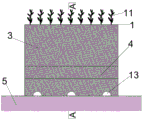
FIG. 1 is a schematic front view of the flood-proof hard shoulder unit in the flood-proof drainage landscape support system of the utility model.
Fig. 2 is a schematic sectional view taken along line a-a of fig. 1.
FIG. 3 is the schematic view of the end face of the flood-proof hard shoulder unit in the flood-proof drainage landscape supporting system of the utility model.
Fig. 4 is a schematic view of the upper assembly base body in the flood-proof drainage landscape support system of the utility model.
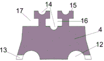
Fig. 5 is a schematic view of the lower component base body in the flood-proof drainage landscape support system of the utility model.
Fig. 6 is a schematic cross-sectional view of the upper and lower component substrates of the flood-proof drainage landscape support system of the present invention.
Fig. 7 is a schematic end view of the upper and lower component substrates of the flood-proof drainage landscape support system of the present invention.
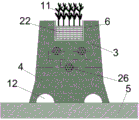
Fig. 8 is a schematic front view of a plurality of flooding-proof hard shoulder connectors in the flooding-proof drainage landscape support system of the present invention.
Fig. 9 is a schematic sectional view taken along line B-B of fig. 8.
Fig. 10 is a schematic end view of a plurality of flood-proof hard shoulder connectors in the flood-proof drainage landscape support system of the present invention.
In the figure: 1 is a flood-proof isolation pier unit; 2, a plurality of flood-proof isolation pier connectors; 3 is the upper composition matrix; 4 is a lower composition matrix; 5 is a road table; 6 is a plant containing box; 7 is a semicircular notch of the upper base body; 8 is a convex end in the middle of the upper substrate; 9 is a convex end of the edge of the upper matrix; 10 is an upper matrix groove; 11 is landscape flower; 12 is a lower end water passing groove; 13 is a water through port; 14 is a lower basal body semicircular notch; 15 is the convex end of the lower base body; 16 is a groove in the middle of the lower substrate; 17 is a groove at the edge of the lower matrix; 18 is a gathering ditch; 19 is a calandria; 20 is a connecting pipe; 21 is a main discharge pipeline; 22 is flower soil; 23 is an emergency calandria; 24 is an anti-accumulation pipe; 25 is a vertical tube; 26 is a connecting penetrating rod of the isolation pier; and 27 is a hard shoulder connecting hole structure.
Detailed Description
For further explanation of the present invention, the following detailed description of the present invention is provided with reference to the drawings and examples, which should not be construed as limiting the scope of the present invention.
A flood-proof drainage landscape support system mainly comprises a flood-proof isolation pier unit 1, a plurality of flood-proof isolation pier connectors 2, an upper composition base body 3, a lower composition base body 4, a road surface 5, a plant containing box 6, an upper base body semicircular notch 7, an upper base body middle convex end 8, an upper base body edge convex end 9, an upper base body groove 10, landscape flowers 11, a lower end water passing groove 12, a water passing setting port 13, a lower base body semicircular notch 14, a lower base body convex end 15, a lower base body middle groove 16, a lower base body edge groove 17, a gathering water ditch 18, a drain pipe 19, a connecting pipe 20, a main drain pipe 21, flower soil 22, an emergency drain pipe 23, an accumulation-proof drain pipe 24, a vertical pipe 25, an isolation pier connecting through rod 26 and an isolation pier connecting hole structure 27, wherein the flood-proof drainage landscape support system is provided with the flood-proof isolation pier unit 1 on the road surface 5, and the flood-proof drainage isolation pier unit 1 is composed of the upper composition base body 3, The lower component basal body 4 is combined, in the structure of the upper component basal body 3, a plant containing box 6 is arranged above the lower component basal body, flower soil 22 is arranged in the plant containing box 6, landscape flowers 11 are planted in the flower soil 22, an upper basal body middle convex end 8 is arranged in the middle of the lower part, an upper basal body edge convex end 9 is respectively arranged at two ends of the lower part, an upper basal body groove 10 is arranged between the upper basal body middle convex end 8 and the upper basal body edge convex end 9, a penetrated upper basal body semicircular notch 7 is respectively arranged at the lower end of the upper basal body middle convex end 8 and the upper end of the upper basal body groove 10, in the structure of the lower component basal body 4, two lower basal body convex ends 15 are arranged above the lower basal body convex end, a lower basal body middle groove 16 is arranged between the two lower basal body convex ends 15, a lower basal body edge groove 17 is arranged at the outer side of the lower basal body convex end 15, and a penetrated lower basal body semicircular notch 14, the lower two sides of the lower composition basal body 4 are respectively provided with a lower water passing groove 12 which is formed by upward sinking and penetrates, the bottom of the side wall of the lower composition basal body 4 is provided with a plurality of water passing setting ports 13, the water passing setting ports 13 are communicated with the lower water passing groove 12, when the upper composition basal body 3 and the lower composition basal body 4 are combined, the convex end 8 in the middle of the upper basal body of the upper composition basal body 3 is inserted into the groove 16 in the middle of the lower basal body of the lower composition basal body 4, the convex end 9 in the edge of the upper basal body of the upper composition basal body 3 is inserted into the groove 17 in the edge of the lower basal body of the lower composition basal body 4, the convex end 15 in the lower basal body of the lower composition basal body 4 is inserted into the groove 10 in the upper basal body of the upper composition basal body 3, when the upper composition basal body 3 and the lower composition basal body 4 are combined, the semicircular notch 7 in the upper basal body, when a plurality of flood-proof isolation pier units 1 are combined into a plurality of flood-proof isolation pier connectors 2, a connecting penetrating rod 26 of the isolation pier can be inserted into an isolation pier connecting hole structure 27, an emergency discharge pipe 23 is arranged at the same time, one end of the emergency discharge pipe is communicated with the upper part of the flower soil 22, the other end of the emergency discharge pipe is communicated with the vertical pipe 25, the other end of the emergency discharge pipe is communicated with the lower part of the flower soil 22, the other end of the emergency discharge pipe is communicated with the lower part of the vertical pipe 25, the lower end of the vertical pipe 25 is communicated with the lower end of the water passing groove 12, the gathering water channels 18 are respectively arranged below the lower end of the water passing groove 12, the discharge pipe 19 is arranged and the bottom of the gathering water channel 18 is communicated, a main discharge pipe 21 is arranged below the.
One end of the emergency calandria 23 and the anti-accumulation calandria 24 arranged in the plant containing box 6 is provided with a soil blocking net.
The sizes of the middle convex end 8 of the upper base body and the middle groove 16 of the lower base body are matched with each other to ensure that the middle convex end 8 of the upper base body can be smoothly inserted into the middle groove 16 of the lower base body.
The sizes of the edge convex end 9 of the upper base body and the edge groove 17 of the lower base body are matched with each other to ensure that the edge convex end 9 of the upper base body can be smoothly inserted into the edge groove 17 of the lower base body.
The dimensions of the lower base body convex end 15 and the upper base body groove 10 are matched with each other to ensure that the lower base body convex end 15 can be smoothly inserted into the upper base body groove 10.
When ponding was too much on the way table 5, its accessible leads to water and sets up mouthful 13 and get into in the lower extreme water passing groove 12 and get into again and assemble ditch 18, and then through calandria 19, connecting pipe 20 gets into main drain 21 and discharges, dredge fast excessive ponding on the road surface effectively, high-efficient discharge, effectively play the effect of flood control, when the plant holds the ponding in the box 6 too much, unnecessary water accessible emergency calandria 23, prevent that ponding pipe 24 gets into standpipe 25, and then get into in the lower extreme water passing groove 12 and get into again and assemble ditch 18.
The distance between the adjacent water through setting ports 13 in the same flood-proof hard shoulder unit 1 is set between 6 m and 11 m.
The foregoing is only a preferred embodiment of the present invention, and it should be noted that, for those skilled in the art, a plurality of modifications and decorations can be made without departing from the principle of the present invention, and these modifications and decorations should also be regarded as the protection scope of the present invention.
Claims (6)
1. The utility model provides a prevent flooding drainage view braced system which characterized in that: the flooding-proof isolation pier comprises flooding-proof isolation pier units (1), a plurality of flooding-proof isolation pier connectors (2), an upper composition base body (3), a lower composition base body (4), a road surface (5), a plant containing box (6), an upper base body semicircular notch (7), an upper base body middle convex end (8), an upper base body side convex end (9), an upper base body groove (10), a lower end water passing groove (12), a water passing setting port (13), a lower base body semicircular notch (14), a lower base body convex end (15), a lower base body middle groove (16), a lower base body side groove (17), a gathering ditch (18), a pipe (19), a connecting pipe (20), a main pipe (21), an emergency pipe (23), an accumulation-proof pipe (24), a vertical pipe (25), an isolation pier connecting penetrating rod (26) and an isolation pier connecting hole structure (27), wherein the flooding-proof isolation pier units (1) are arranged on the road surface (5), the flood-proof hard shoulder unit (1) is formed by combining an upper composition base body (3) and a lower composition base body (4), wherein a plant containing box (6) is arranged above the upper composition base body (3), an upper base body middle convex end (8) is arranged in the middle of the lower portion of the upper base body, upper base body edge convex ends (9) are respectively arranged at two ends of the lower portion of the upper composition base body (3), an upper base body groove (10) is arranged between the upper base body middle convex end (8) and the upper base body edge convex end (9), a penetrating upper base body semicircular notch (7) is respectively arranged at the lower end of the upper base body middle convex end (8) and the upper end of the upper base body groove (10), two lower base body convex ends (15) are arranged above the lower composition base body (4), a lower base body middle groove (16) is arranged between the two lower base body convex ends (15), and a lower base body edge groove (17) is, the upper end of the convex end (15) of the lower base body and the lower end of the groove (16) in the middle of the lower base body are respectively provided with a lower semi-circular notch (14) which penetrates through, both sides of the lower part of the lower composition base body (4) are respectively provided with a lower water passing groove (12) which penetrates through and is formed by sinking upwards, the bottom of the side wall of the lower composition base body (4) is provided with a plurality of water passing setting ports (13), the water passing setting ports (13) are communicated with the lower water passing groove (12), when the upper composition base body (3) and the lower composition base body (4) are combined, the convex end (8) in the middle of the upper base body of the upper composition base body (3) is arranged in the groove (16) in the middle of the lower base body of the lower composition base body (4), the convex end (9) in the edge of the upper base body of the upper composition base body (3) is arranged in the groove (17) in the lower base body of the lower composition base body (4), the convex end (15, when the upper composition base body (3) and the lower composition base body (4) are combined, the upper base body semicircular notch (7) and the lower base body semicircular notch (14) form a barrier pier connecting hole structure (27) inserted into a barrier pier connecting penetrating rod (26), when a plurality of anti-flooding barrier pier units (1) are combined into a plurality of anti-flooding barrier pier connectors (2), the barrier pier connecting penetrating rod (26) is arranged in the barrier pier connecting hole structure (27), an emergency discharge pipe (23) is arranged at the same time, one end of the emergency discharge pipe is communicated with the upper part of the flower soil (22), the other end of the emergency discharge pipe is communicated with a vertical pipe (25), one end of the emergency discharge pipe is communicated with the bottom of the flower soil (22), the other end of the emergency discharge pipe is communicated with the vertical pipe (25), the lower end of the vertical pipe (25) is communicated with the lower end water passing groove (12), a gathering ditch (18) is respectively arranged below the lower end water passing groove (12), and a gathering pipe (19) is, a main row pipeline (21) is arranged below the road meter (5), and a connecting pipe (20) is arranged to communicate the row pipe (19) with the main row pipeline (21).
2. The flood-proof drainage landscape support system according to claim 1, wherein: one end of the emergency calandria (23) and the accumulation-proof calandria (24) arranged in the plant containing box (6) is provided with a soil blocking net.
3. The flood-proof drainage landscape support system according to claim 1, wherein: the sizes of the convex end (8) in the middle of the upper matrix and the groove (16) in the middle of the lower matrix are matched with each other.
4. The flood-proof drainage landscape support system according to claim 1, wherein: the sizes of the edge convex end (9) of the upper matrix and the edge groove (17) of the lower matrix are matched with each other.
5. The flood-proof drainage landscape support system according to claim 1, wherein: the sizes of the convex end (15) of the lower base body and the groove (10) of the upper base body are matched with each other.
6. The flood-proof drainage landscape support system according to claim 1, wherein: the distance between the adjacent water through setting ports (13) in the same flood-proof hard shoulder unit (1) is 6-11 m.
Priority Applications (1)
| Application Number | Priority Date | Filing Date | Title |
|---|---|---|---|
| CN202022044776.7U CN212426873U (en) | 2020-09-17 | 2020-09-17 | Flooding-proof drainage landscape support system |
Applications Claiming Priority (1)
| Application Number | Priority Date | Filing Date | Title |
|---|---|---|---|
| CN202022044776.7U CN212426873U (en) | 2020-09-17 | 2020-09-17 | Flooding-proof drainage landscape support system |
Publications (1)
| Publication Number | Publication Date |
|---|---|
| CN212426873U true CN212426873U (en) | 2021-01-29 |
Family
ID=74279659
Family Applications (1)
| Application Number | Title | Priority Date | Filing Date |
|---|---|---|---|
| CN202022044776.7U Expired - Fee Related CN212426873U (en) | 2020-09-17 | 2020-09-17 | Flooding-proof drainage landscape support system |
Country Status (1)
| Country | Link |
|---|---|
| CN (1) | CN212426873U (en) |
-
2020
- 2020-09-17 CN CN202022044776.7U patent/CN212426873U/en not_active Expired - Fee Related
Similar Documents
| Publication | Publication Date | Title |
|---|---|---|
| US11470787B2 (en) | Salt-isolated rain garden structure | |
| CN207813108U (en) | A kind of Rain Garden | |
| CN106638219A (en) | Ramped urban road of sponge city | |
| CN109403181A (en) | A kind of porous pavement | |
| CN111979953A (en) | Flooding-proof drainage landscape support system | |
| CN202718027U (en) | Water storage and recharged permeable brick combination device | |
| CN109252470A (en) | A kind of expressway greening isolation strip and its construction method | |
| CN212426873U (en) | Flooding-proof drainage landscape support system | |
| CN211080261U (en) | Highway side slope protective structure | |
| CN201137308Y (en) | Human and vehicle shunting type villa group | |
| CN211210711U (en) | Green belt for assembled landscape design | |
| CN213507894U (en) | Permeable pavement for sidewalk | |
| CN111608044A (en) | Compromise street both sides afforestation structure of drainage and road guide | |
| Daly et al. | A Responsible Urban Rejuvenation of Jakarta | |
| CN101122147A (en) | Town rain zero discharge system engineering | |
| CN110952500A (en) | Retaining wall structure for city environmental protection construction | |
| CN215011948U (en) | Landscape design's plant buffering area structure | |
| CN219710778U (en) | Roof rainwater garden | |
| CN214193987U (en) | Pavement brick with conical water permeable holes | |
| CN217299204U (en) | Smooth open channel drainage system | |
| CN204940048U (en) | A kind of Afforestation Landscape road | |
| CN217783076U (en) | Ground embedded ecological grave structure | |
| CN212335683U (en) | Landscape structure of mating formation | |
| CN215925469U (en) | Biodiversity overpass plaque structure | |
| CN212506005U (en) | Municipal afforestation median |
Legal Events
| Date | Code | Title | Description |
|---|---|---|---|
| GR01 | Patent grant | ||
| GR01 | Patent grant | ||
| CF01 | Termination of patent right due to non-payment of annual fee | ||
| CF01 | Termination of patent right due to non-payment of annual fee |
Granted publication date: 20210129 Termination date: 20210917 |