CN212237473U - Coal breaker for sintering batching - Google Patents
Coal breaker for sintering batching Download PDFInfo
- Publication number
- CN212237473U CN212237473U CN202020732010.5U CN202020732010U CN212237473U CN 212237473 U CN212237473 U CN 212237473U CN 202020732010 U CN202020732010 U CN 202020732010U CN 212237473 U CN212237473 U CN 212237473U
- Authority
- CN
- China
- Prior art keywords
- fixedly connected
- box
- crushing
- inner cavity
- transmission shaft
- Prior art date
- Legal status (The legal status is an assumption and is not a legal conclusion. Google has not performed a legal analysis and makes no representation as to the accuracy of the status listed.)
- Active
Links
Images


Abstract
The utility model belongs to the field of coal, in particular to a coal crushing device for sintering batching, which aims at the problems that the crushing effect of the existing crushing device is poor and the wastes generated after the processing are easy to cause harm to the environment and the working personnel, and provides a proposal that the device comprises a support frame, wherein the left part and the right part of the bottom wall of an inner cavity of the support frame are both fixedly connected with a first spring, the rear wall of the inner cavity of the support frame is fixedly provided with a first motor, the output end of the first motor is fixedly connected with a connecting shaft, the front end of the connecting shaft is fixedly connected with an eccentric wheel, the upper part of the inner cavity of a crushing box is provided with a crushing device, the middle part of the inner cavity of the crushing box is fixedly connected with a first filter screen, and the raw materials can be screened by arranging the first spring and a second spring, the first filter screen can be prevented from being, through setting up the fan to can less harmful gas to environment and staff's injury.
Description
Technical Field
The utility model relates to a coal field, in particular to coal breaker is used in sintering batching.
Background
Coal is a solid combustible mineral formed by ancient plants buried underground and undergoing complex biochemical and physicochemical changes, is known as black gold by people, is industrial food, is one of main energy sources used in the human world in the eighteenth century, enters the twenty-first century, has great value as before, but is one of indispensable energy sources for production and life of human beings in the long time at present and in the future, and coal is used in sintering ingredients.
The crushing effect of the existing crushing device on the raw materials is poor, the crushed raw materials are directly conveyed out without being screened, so that a part of coal is crushed and unqualified, a large amount of waste gas is generated after the coal is processed, the coal is easily harmed to the external environment and workers along with the discharge of the crushed raw materials, and therefore the coal crushing device for sintering and batching is provided.
Disclosure of Invention
The utility model aims to provide a coal breaker is used in sintering batching can effectively solve the not good and abandonment that appears after the processing is accomplished of current breaker crushing effect and produce the problem of harm to environment and staff easily.
In order to achieve the above purpose, the utility model adopts the following technical scheme:
a coal crushing device for sintering batching comprises a support frame, wherein sliding grooves are formed in the left wall and the right wall of an inner cavity of the support frame, first springs are fixedly connected to the left portion and the right portion of the bottom wall of the inner cavity of the support frame, first supporting plates are fixedly connected to the upper ends of the first springs together, second springs are fixedly connected to the left portion and the right portion of the upper end of the first supporting plate, second supporting plates are fixedly connected to the upper ends of the second springs together, sliding blocks are fixedly connected to the left end and the right end of each of the first supporting plate and the second supporting plate, a first motor is fixedly installed on the rear wall of the inner cavity of the support frame, a connecting shaft is fixedly connected to the output end of the first motor, an eccentric wheel is fixedly connected to the front end of the connecting shaft, a crushing box is fixedly connected to the upper end of each of the second supporting plate, the crushing device is arranged on the upper portion of the inner cavity of the crushing box, the fixing plate is fixedly connected to the rear end of the crushing box, the first filter screen is fixedly connected to the middle of the inner cavity of the crushing box, and the protection box is fixedly connected to the front end of the crushing box.
Preferably, the four sliding blocks are respectively connected with the two sliding grooves in a sliding manner at one end far away from the second supporting plate and the first supporting plate, and the eccentric wheel is positioned between the second supporting plate and the first supporting plate.
Preferably, the reducing mechanism includes the second motor, second motor fixed mounting is in the upper end of fixed plate, the first transmission shaft of output fixedly connected with of second motor, the rear wall that the front end of first transmission shaft runs through broken case extends to its inner chamber, the inner chamber left part of broken case is connected with the second transmission shaft through the bearing transmission, the rear wall that the rear end of second transmission shaft runs through broken case extends to the outside, the equal fixedly connected with gear in surface rear portion of second transmission shaft and first transmission shaft, the equal fixedly connected with of surface of first transmission shaft and second transmission shaft smashes the kun.
Preferably, the lower part of the inner cavity of the protection box is fixedly connected with a material outlet box, the rear part of the upper end of the protection box is fixedly provided with a second filter screen, the inner cavity of the second filter screen is fixedly provided with a fan, the front part of the upper end of the protection box is fixedly connected with a dust collection box, and the upper part of the inner cavity of the dust collection box is fixedly connected with an equipment box.
Preferably, go out the magazine and be the slope structure, ejection of compact box is located the protective housing lower part and laminates mutually rather than, fixedly connected with pipe between second filter screen and the protective housing, and a plurality of connecting pipe of fixedly connected with between equipment box and the protective housing, a plurality of connecting pipe all are located the top of going out the magazine.
Preferably, the outer surfaces of the two gears are engaged with each other, and the crushing blades on the outer surfaces of the two crushing rollers are distributed in a staggered manner.
Compared with the prior art, the utility model discloses following beneficial effect has:
(1) through setting up first spring and second spring, because the characteristic of eccentric wheel, first motor passes through connecting axle and eccentric wheel fixed connection, drives second backup pad and second backup pad then and shakes from top to bottom, can drive the raw materials in the broken incasement in top then and reach the effect that rolls, can filter the raw materials then, and can avoid first filter screen to block up, and two crushing kun of being convenient for smash the raw materials.
(2) Through setting up the fan to and the inner chamber fixedly connected with equipment box of dust collection box, a plurality of connecting pipe of fixedly connected with between dust collection box and the ejection of compact box, the harmful gas who produces when then can come out the raw materials through wind-force absorbs, thereby can less harmful gas to environment and staff's injury, play the guard action to the nature to a certain extent.
Drawings
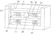
FIG. 1 is a schematic view of the overall structure of a coal crushing device for sintering and blending of the present invention;
FIG. 2 is a schematic view of the internal structure of the supporting frame of the coal crushing device for sintering and blending of the present invention;
FIG. 3 is a schematic structural view of a crushing device of the coal crushing device for sintering and blending of the present invention;
fig. 4 is a bottom view of the coal crushing device for sintering and proportioning of the present invention.
In the figure: 1. a support frame; 2. a first support plate; 21. a chute; 22. a slider; 23. a first spring; 24. a first motor; 25. a connecting shaft; 26. an eccentric wheel; 27. a second spring; 28. a second support plate; 3. a crushing box; 4. a crushing device; 41. a second motor; 42. a first drive shaft; 43. a second drive shaft; 44. a gear; 45. a crushing roller; 5. a feed hopper; 6. a fixing plate; 7. a first filter screen; 8. a protective box; 81. discharging the material box; 82. a dust collection box; 83. an equipment box; 84. a second filter screen; 85. a connecting pipe; 86. a fan.
Detailed Description
In order to make the technical means, creation features, achievement purposes and functions of the present invention easy to understand, the present invention is further described below with reference to the following embodiments.
In the description of the present invention, it should be noted that the terms "upper", "lower", "inner", "outer", "front end", "rear end", "both ends", "one end", "the other end" and the like indicate orientations or positional relationships based on the orientations or positional relationships shown in the drawings, and are only for convenience of description and simplification of description, but do not indicate or imply that the device or element to which the reference is made must have a specific orientation, be constructed in a specific orientation, and be operated, and thus, should not be construed as limiting the present invention. Furthermore, the terms "first" and "second" are used for descriptive purposes only and are not to be construed as indicating or implying relative importance.
In the description of the present invention, it is to be noted that, unless otherwise explicitly specified or limited, the terms "mounted," "disposed," "connected," and the like are to be construed broadly, and for example, "connected" may be either fixedly connected or detachably connected, or integrally connected; can be mechanically or electrically connected; they may be connected directly or indirectly through intervening media, or they may be interconnected between two elements. The specific meaning of the above terms in the present invention can be understood in specific cases to those skilled in the art.
As shown in FIGS. 1-4, a coal crushing device for sintering burden comprises a support frame 1, a chute 21 is arranged on both left and right walls of an inner cavity of the support frame 1, first springs 23 are fixedly connected to both left and right parts of the bottom wall of the inner cavity of the support frame 1, a first support plate 2 is fixedly connected to the upper ends of the two first springs 23, a second spring 27 is fixedly connected to both left and right parts of the upper end of the first support plate 2, a second support plate 28 is fixedly connected to the upper ends of the two second springs 27, sliders 22 are fixedly connected to both left and right ends of the first support plate 2 and the second support plate 28, a first motor 24 is fixedly mounted on the rear wall of the inner cavity of the support frame 1, a connecting shaft 25 is fixedly connected to the output end of the first motor 24, an eccentric wheel 26 is fixedly connected to the front end of the connecting shaft 25, a crushing box 3 is fixedly connected to the upper end of the second support plate, the upper portion of the inner cavity of the crushing box 3 is provided with a crushing device 4, the rear end of the crushing box 3 is fixedly connected with a fixing plate 6, the middle portion of the inner cavity of the crushing box 3 is fixedly connected with a first filter screen 7, and the front end of the crushing box 3 is fixedly connected with a protection box 8.
One ends of the four sliding blocks 22 far away from the second supporting plate 28 and the first supporting plate 2 are respectively in sliding connection with the two sliding grooves 21, and the eccentric wheel 26 is positioned between the second supporting plate 28 and the first supporting plate 2, so that the raw materials can roll.
The crushing device 4 comprises a second motor 41, the second motor 41 is fixedly mounted at the upper end of the fixing plate 6, the first transmission shaft 42 is fixedly connected to the output end of the second motor 41, the front end of the first transmission shaft 42 penetrates through the rear wall of the crushing box 3 and extends to the inner cavity of the crushing box, the left part of the inner cavity of the crushing box 3 is connected with a second transmission shaft 43 through bearing transmission, the rear end of the second transmission shaft 43 penetrates through the rear wall of the crushing box 3 and extends to the outside, gears 44 are fixedly connected to the rear parts of the outer surfaces of the second transmission shaft 43 and the first transmission shaft 42, and crushing rollers 45 are fixedly connected to the outer surfaces of the first transmission shaft 42 and the second transmission shaft 43, so that the crushing effect.
The inner chamber lower part fixedly connected with of guard box 8 goes out magazine 81, and the upper end rear portion fixedly mounted of guard box 8 has second filter screen 84, and the inner chamber fixed mounting of second filter screen 84 has fan 86, the anterior fixedly connected with dust collection box 82 of upper end of guard box 8, and the inner chamber upper portion fixedly connected with equipment box 83 of dust collection box 82 is favorable to purifying waste gas.
Go out magazine 81 and be the slope structure, ejection of compact box 81 is located 8 lower parts of protective housing and laminates mutually rather than, fixedly connected with pipe between second filter screen 84 and the protective housing 8, a plurality of connecting pipe 85 of fixedly connected with between equipment box 83 and the protective housing 8, a plurality of connecting pipe 85 all is located the top of going out magazine 81, is convenient for carry out the raw materials.
The outer surfaces of the two gears 44 are engaged with each other, and the crushing blades on the outer surfaces of the two crushing rollers 45 are distributed in a staggered manner.
It should be noted that, the utility model relates to a coal crushing device for sintering burden, the worker starts the machine first, then put the raw material into the inner cavity of the crushing box 3 from the feeding hopper 5, the second motor 41 drives the gear 44 on the outer surface of the first transmission shaft 42 to rotate, then the gear 44 drives the second transmission shaft 43 connected with another gear 44 to rotate, so that the two crushing rollers 45 rotate in opposite directions, so that the two crushing rollers 45 crush the raw material, the first motor 24 is started, the eccentric wheel 26 is driven to rotate by the connecting shaft 25, then the second supporting plate 28 and the first supporting plate 2 are pushed to move up and down, then the crushing box 3 is vibrated, so that the raw material inside the crushing box 3 rolls, and falls into the discharging box 81 through the filter holes on the first filter screen 7, the fan 86 is started, the dust collecting box 82 is generated by wind power through the guide pipe, then absorb the harmful gas that material processing produced through connecting pipe 85, equipment box 83 can carry out the separation to gas, makes it persist in dust collection box 82, then through going out magazine 81 landing to the outside, and the staff puts the collecting box in advance in the below of ejection of compact box 81, and later the staff opens the looks door of dust collection box 82 front end, and it can to clear up impurity.
The basic principles and the main features of the invention and the advantages of the invention have been shown and described above. It will be understood by those skilled in the art that the present invention is not limited to the above embodiments, and that the foregoing embodiments and descriptions are provided only to illustrate the principles of the present invention without departing from the spirit and scope of the present invention. The scope of the invention is defined by the appended claims and equivalents thereof.
Claims (6)
1. The utility model provides a coal breaker for sintering batching, includes support frame (1), its characterized in that: the inner cavity left wall and the right wall of the support frame (1) are both provided with a sliding groove (21), the left part and the right part of the inner cavity bottom wall of the support frame (1) are both fixedly connected with a first spring (23), the upper ends of the two first springs (23) are both fixedly connected with a first support plate (2), the upper end left part and the right part of the first support plate (2) are both fixedly connected with a second spring (27), the upper ends of the two second springs (27) are both fixedly connected with a second support plate (28), the left end and the right end of the first support plate (2) and the second support plate (28) are both fixedly connected with a sliding block (22), the inner cavity rear wall of the support frame (1) is fixedly provided with a first motor (24), the output end of the first motor (24) is fixedly connected with a connecting shaft (25), the front end of the connecting shaft (25) is fixedly connected with an eccentric, the crushing case of upper end fixedly connected with (3) of second backup pad (28), the upper end of crushing case (3) alternates and is connected with feeder hopper (5), the inner chamber upper portion of crushing case (3) is provided with reducing mechanism (4), the rear end fixedly connected with fixed plate (6) of crushing case (3), the first filter screen of inner chamber middle part fixedly connected with (7) of crushing case (3), the front end fixedly connected with protecting box (8) of crushing case (3).
2. The coal crushing device for sintering burden as claimed in claim 1, wherein: one end, far away from the second supporting plate (28) and the first supporting plate (2), of each of the four sliding blocks (22) is in sliding connection with the two sliding grooves (21), and the eccentric wheel (26) is located between the second supporting plate (28) and the first supporting plate (2).
3. The coal crushing device for sintering burden as claimed in claim 1, wherein: reducing mechanism (4) include second motor (41), second motor (41) fixed mounting is in the upper end of fixed plate (6), the first transmission shaft (42) of output fixedly connected with of second motor (41), the rear wall that the front end of first transmission shaft (42) runs through broken case (3) extends to its inner chamber, the inner chamber left part of broken case (3) is connected with second transmission shaft (43) through the bearing transmission, the rear wall that the rear end of second transmission shaft (43) runs through broken case (3) extends to the outside, the equal fixedly connected with gear (44) in surface rear portion of second transmission shaft (43) and first transmission shaft (42), the equal fixedly connected with in surface of first transmission shaft (42) and second transmission shaft (43) smashes pinch roller (45).
4. The coal crushing device for sintering burden as claimed in claim 1, wherein: the device is characterized in that a material outlet box (81) is fixedly connected to the lower portion of an inner cavity of the protection box (8), a second filter screen (84) is fixedly mounted on the rear portion of the upper end of the protection box (8), a fan (86) is fixedly mounted in the inner cavity of the second filter screen (84), a dust collection box (82) is fixedly connected to the front portion of the upper end of the protection box (8), and an equipment box (83) is fixedly connected to the upper portion of the inner cavity of the dust collection box (82).
5. The coal crushing device for sintering burden as claimed in claim 4, wherein: go out magazine (81) and be the slope structure, go out magazine (81) and be located protecting box (8) lower part and laminate rather than mutually, fixedly connected with pipe between second filter screen (84) and protecting box (8), a plurality of connecting pipe (85) of fixedly connected with between equipment box (83) and protecting box (8), a plurality of connecting pipe (85) all are located the top of going out magazine (81).
6. The coal crushing device for sintering burden as claimed in claim 3, wherein: the outer surfaces of the two gears (44) are meshed, and the crushing leaves on the outer surfaces of the two crushing rollers (45) are distributed in a staggered mode.
Priority Applications (1)
| Application Number | Priority Date | Filing Date | Title |
|---|---|---|---|
| CN202020732010.5U CN212237473U (en) | 2020-05-07 | 2020-05-07 | Coal breaker for sintering batching |
Applications Claiming Priority (1)
| Application Number | Priority Date | Filing Date | Title |
|---|---|---|---|
| CN202020732010.5U CN212237473U (en) | 2020-05-07 | 2020-05-07 | Coal breaker for sintering batching |
Publications (1)
| Publication Number | Publication Date |
|---|---|
| CN212237473U true CN212237473U (en) | 2020-12-29 |
Family
ID=73998575
Family Applications (1)
| Application Number | Title | Priority Date | Filing Date |
|---|---|---|---|
| CN202020732010.5U Active CN212237473U (en) | 2020-05-07 | 2020-05-07 | Coal breaker for sintering batching |
Country Status (1)
| Country | Link |
|---|---|
| CN (1) | CN212237473U (en) |
Cited By (1)
| Publication number | Priority date | Publication date | Assignee | Title |
|---|---|---|---|---|
| CN113600285A (en) * | 2021-10-09 | 2021-11-05 | 江苏福瑞士电池科技有限公司 | Breaker that lithium iron phosphate battery retrieved |
-
2020
- 2020-05-07 CN CN202020732010.5U patent/CN212237473U/en active Active
Cited By (2)
| Publication number | Priority date | Publication date | Assignee | Title |
|---|---|---|---|---|
| CN113600285A (en) * | 2021-10-09 | 2021-11-05 | 江苏福瑞士电池科技有限公司 | Breaker that lithium iron phosphate battery retrieved |
| CN113600285B (en) * | 2021-10-09 | 2021-12-07 | 江苏福瑞士电池科技有限公司 | Breaker that lithium iron phosphate battery retrieved |
Similar Documents
| Publication | Publication Date | Title |
|---|---|---|
| CN211706891U (en) | Reducing mechanism for building rubbish | |
| CN212237473U (en) | Coal breaker for sintering batching | |
| CN114798112A (en) | New energy automobile battery recovery unit | |
| CN216322229U (en) | Take dust to collect lime stone breaker of mechanism | |
| CN214159992U (en) | Waste treatment device for building engineering | |
| CN212418127U (en) | Feeding dustproof ore crusher | |
| CN212328556U (en) | Broken crocus integrated device of coal cinder | |
| CN211385300U (en) | Reducing mechanism for lithium ion battery cathode material | |
| CN210159732U (en) | High-efficient rubble device is used to mining machinery | |
| CN115445735B (en) | Garbage crushing shredder with dust isolation function | |
| CN216606604U (en) | Waste treatment device for wood processing | |
| CN217614894U (en) | Be used for coal reducing mechanism for deep-processing | |
| CN212284165U (en) | Coal mine crushing device for coal mining | |
| CN214916905U (en) | High-efficient reducing mechanism of new forms of energy living beings | |
| CN213050780U (en) | Noise reduction type crusher with dustproof function | |
| CN211755322U (en) | Grinding device is used in cosmetics production | |
| CN210097789U (en) | Corrugated paper waste material reducing mechanism | |
| CN215783647U (en) | High-quality multistage milling machine of plastic steel section bar | |
| CN217189980U (en) | High-efficient industrial chemicals reducing mechanism | |
| CN212069052U (en) | Automatic control system of pulverizer | |
| CN214439611U (en) | Based on middling pressure variable frequency control coal grinds device | |
| CN218189918U (en) | Waste material breaker for construction | |
| CN218013029U (en) | Coal mine crusher | |
| CN217323969U (en) | Industrial continuous waste tire cracking device | |
| CN215395784U (en) | Waste collecting device is used in production of bridge opening dynamics board |
Legal Events
| Date | Code | Title | Description |
|---|---|---|---|
| GR01 | Patent grant | ||
| GR01 | Patent grant |