CN212008978U - Automatic attack tooth check out test set - Google Patents
Automatic attack tooth check out test set Download PDFInfo
- Publication number
- CN212008978U CN212008978U CN202020541704.0U CN202020541704U CN212008978U CN 212008978 U CN212008978 U CN 212008978U CN 202020541704 U CN202020541704 U CN 202020541704U CN 212008978 U CN212008978 U CN 212008978U
- Authority
- CN
- China
- Prior art keywords
- block
- detection
- variable
- pitch
- cylinder
- Prior art date
- Legal status (The legal status is an assumption and is not a legal conclusion. Google has not performed a legal analysis and makes no representation as to the accuracy of the status listed.)
- Expired - Fee Related
Links
- 238000012360 testing method Methods 0.000 title claims abstract description 13
- 238000001514 detection method Methods 0.000 claims abstract description 110
- 238000010079 rubber tapping Methods 0.000 claims abstract description 76
- 230000007246 mechanism Effects 0.000 claims abstract description 66
- 238000011027 product recovery Methods 0.000 claims abstract description 12
- 210000001503 joint Anatomy 0.000 claims abstract description 8
- 238000003825 pressing Methods 0.000 claims description 43
- 238000012546 transfer Methods 0.000 claims description 21
- 239000000872 buffer Substances 0.000 claims description 17
- 239000000463 material Substances 0.000 claims description 17
- 239000000523 sample Substances 0.000 claims description 10
- 230000000712 assembly Effects 0.000 claims description 8
- 238000000429 assembly Methods 0.000 claims description 8
- 239000000969 carrier Substances 0.000 claims description 7
- 230000017105 transposition Effects 0.000 claims description 7
- 239000013307 optical fiber Substances 0.000 claims description 4
- 238000004519 manufacturing process Methods 0.000 abstract description 6
- 230000002457 bidirectional effect Effects 0.000 description 5
- 238000002360 preparation method Methods 0.000 description 5
- 238000012545 processing Methods 0.000 description 5
- 238000010586 diagram Methods 0.000 description 3
- 238000007689 inspection Methods 0.000 description 3
- 238000000034 method Methods 0.000 description 3
- 241000252254 Catostomidae Species 0.000 description 1
- 230000009286 beneficial effect Effects 0.000 description 1
- 230000007547 defect Effects 0.000 description 1
- 238000013461 design Methods 0.000 description 1
- 238000007599 discharging Methods 0.000 description 1
- 238000005516 engineering process Methods 0.000 description 1
- 238000012423 maintenance Methods 0.000 description 1
- 238000004064 recycling Methods 0.000 description 1
- 230000033764 rhythmic process Effects 0.000 description 1
Images


Abstract
The utility model discloses an automatic attack tooth check out test set, this kind of automatic attack tooth check out test set include frame, dislocation formula casing feed mechanism, coordinated type move carry the mechanism, the blind hole is attacked tooth detection mechanism, through-hole and is attacked tooth detection mechanism, finished product recovery unit, garbage collection box and guard shield, install coordinated type in the frame and move the mechanism, coordinated type moves and carries the mechanism left side butt joint and be provided with dislocation formula casing feed mechanism, and coordinated type moves and carries the mechanism rear side and be provided with five-station blind holes and attack tooth detection mechanism and quadruplex position through-hole and attack tooth detection mechanism, and coordinated type moves and carries the mechanism right side butt joint and be provided with finished product recovery unit, and coordinated type moves and carries the mechanism lower extreme and be provided with the garbage collection box, still installs. In this way, the utility model discloses compact structure operates steadily, can carry out the tapping of blind hole and through-hole to product relevant position department automatically and handle, and two station simplex position switch freely, detect whether have the screw tap in the tapping, practice thrift the labour, improve production efficiency.
Description
Technical Field
The utility model relates to a machine-building technical field especially relates to an automatic attack tooth check out test set.
Background
When the traditional tapping equipment is used for processing threaded holes of workpieces, the tapping equipment controls the screw tap to vertically move from top to bottom so as to tap the workpieces positioned and clamped on the horizontal working platform, because the traditional tapping equipment can only control the screw tap to vertically move, when the workpieces are long and rows of threaded holes need to be processed on the long edge, the tapping equipment controls the screw tap to horizontally push the workpieces until the position of the screw tap is just opposite to the next position to be tapped of the workpieces after each frequency of processing is finished by the traditional tapping equipment, then the tapping equipment controls the screw tap to process the next frequency after the workpieces are repositioned and clamped, therefore, in the processing process, the workpieces need to be clamped and positioned for many times, the processing efficiency can be greatly reduced, meanwhile, the accumulated positioning error can be caused by the clamping and positioning of the workpieces for many times, the processing precision is influenced, and because the processed workpieces often need at least two operators to complete the shifting and positioning and clamping of the workpieces, therefore, the labor cost is high, the overall production cost is not high, in addition, a tapping tool needs to be detected before tapping every time, the production rhythm is influenced, the tapping requirements on the same product are different, namely, through holes or blind holes are formed in positions a, b, c and d, the through holes are formed in positions e, f and g, tapping equipment needs to be switched, and on the basis of the defects, the existing technology needs to be improved, and the automatic tapping detection equipment is designed.
SUMMERY OF THE UTILITY MODEL
The utility model discloses the main technical problem who solves provides an automatic tapping check out test set, compact structure, operates steadily, can carry out the tapping of blind hole and through-hole to product relevant position department automatically and handle, and the duplex position unit position switches freely, detects whether have or not screw tap in the tapping, practices thrift the labour, improves production efficiency.
In order to solve the technical problem, the utility model discloses a technical scheme be: the utility model provides an automatic attack tooth check out test set, this kind of automatic attack tooth check out test set include frame, dislocation formula casing feed mechanism, coordinated type move carry the mechanism, the blind hole is attacked tooth detection mechanism, through-hole and is attacked tooth detection mechanism, finished product recovery unit, garbage collection box and guard shield, install coordinated type in the frame and move the mechanism, coordinated type moves and carries the butt joint in mechanism left side and is provided with dislocation formula casing feed mechanism, and coordinated type moves and carries the mechanism rear side and is provided with five-station blind hole and attacks tooth detection mechanism and quadruplex position through-hole, and coordinated type moves and carries the butt joint in mechanism right side and be provided with finished product recovery unit, and coordinated type moves and carries the mechanism lower extreme and be provided with the garbage collection box, still.
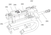
Preferably, the dislocation type shell feeding mechanism comprises a shell vibration disc, a guide block, a feeding support, a dislocation cylinder, a bearing module, an in-place sensor, a transposition mechanical arm and a double-station carrier seat assembly, wherein the guide block is butted with a linear feeder of the shell vibration disc, the guide block is arranged on the feeding support, the dislocation cylinder is arranged on the feeding support, the bearing module is arranged on the dislocation cylinder, the bearing module is butted with the guide block, the in-place sensor is arranged on the bearing module, a product mounting groove is formed in the bearing module, and the transposition mechanical arm and the double-station carrier seat assembly are arranged on the rear side of the bearing module; the double-station carrier seat assembly comprises a carrier bracket, a linear slide rail, a carrier seat block, a pen-shaped air cylinder, a buffer, a sliding table air cylinder, a standby material block and a product in-place optical fiber, the bearing support is fixed on the rack, a linear slide rail is mounted on a workbench of the bearing support, a bearing block is mounted on the linear slide rail, a pen-shaped air cylinder with the direction consistent with that of the linear slide rail is mounted on the bearing support, a telescopic rod of the pen-shaped air cylinder is fixed with the bearing block, buffers opposite to the bearing block are mounted at two ends of the linear slide rail, a sliding table air cylinder perpendicular to the linear slide rail is further mounted on the workbench of the bearing support, a material preparation block is mounted on a sliding table of the sliding table air cylinder, product placing grooves are formed in the bearing block and the material preparation block, product in-place optical fibers are further arranged on the bearing block and the material preparation block, and the pen-shaped air cylinder and the sliding table air cylinder are matched to adjust the distance between the bearing block and the.
Preferably, the linkage type transfer mechanism comprises a screw rod carrying module, a follow-up carrying module, a vertical bearing seat and a bidirectional fisheye bearing, the moving plates of the screw rod carrying module and the follow-up carrying module are provided with vertical bearing blocks, the two vertical bearing blocks are movably connected through a bidirectional fisheye bearing, the screw rod conveying module comprises a conveying bracket, a linear moving and carrying rail, a moving and carrying plate, a screw rod, a servo motor, a connecting block and an up-and-down conveying assembly, the conveying support is provided with two linear moving and carrying slide rails, a moving and carrying plate is arranged on a slide block of each linear moving and carrying slide rail, a lead screw and a servo motor are arranged on the conveying support, the servo motor drives the lead screw to rotate, a lead screw nut of the lead screw is provided with a connecting block, the conveying support is provided with an avoiding hole, the connecting block penetrates through the avoiding hole to be fixed with the moving and carrying plate, and five groups of up-and-down conveying assemblies are arranged on the moving and carrying plate in an; the upper and lower carrying assembly comprises a push-pull cylinder, a push plate, an upper and lower cylinder, a moving frame and a sucker, the push plate is arranged on a telescopic rod of the push-pull cylinder, the upper and lower cylinder is arranged on the push plate, the moving frame is arranged on a telescopic rod of the upper and lower cylinder, and the sucker is arranged on a horizontal plate of the moving frame.
Preferably, the follow-up carrying module comprises a follow-up support, a follow-up linear slide rail, a follow-up moving carrier plate, a variable-pitch carrying assembly and follow-up-and-down carrying assemblies, wherein the follow-up support is provided with the follow-up linear slide rail; the variable-pitch carrying assembly comprises a variable-pitch stretching cylinder, a variable-pitch connecting frame, a variable-pitch lifting cylinder, a lifting plate, a variable-pitch pen-shaped cylinder, a guide slide rail, a variable-pitch push plate, a variable-pitch sucker, a positioning block and a limiting block, the variable-pitch stretching cylinder is fixed on the follow-up moving carrier plate, a variable-pitch connecting frame is arranged on a telescopic rod of the variable-pitch stretching cylinder, a variable-pitch lifting cylinder is arranged on a vertical plate of the variable-pitch connecting frame, a lifting plate is arranged on a telescopic rod of the variable-pitch lifting cylinder, the lifting plate is horizontally arranged, two variable-pitch pen-shaped air cylinders are arranged on the lifting plate in a back-to-back manner, two guide slide rails are arranged on the bottom surface of the lifting plate, a variable-pitch push plate is arranged on a slide block of each guide slide rail, telescopic rods of the two variable-pitch pen-shaped air cylinders are respectively fixed with the variable-pitch push plate, a variable-pitch sucker is arranged at the extending end of the variable-pitch push plate, a positioning block is arranged at the rear end of the lifting plate, and a limiting block opposite to the positioning block is arranged on the variable; the structure of the follow-up-down conveying assembly is the same as that of the up-down conveying assembly.
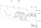
Preferably, the blind hole tapping detection mechanism comprises a flow channel support, product carriers, a pressing assembly, a tapping device and a detection probe assembly, wherein the flow channel support is arranged on a rack workbench, the product carriers for placing products are arranged on the flow channel support in an array manner, the pressing assembly is mounted on the flow channel support at the rear side of the product carriers, the tapping device is arranged at the rear side of the pressing assembly, the detection probe assembly is mounted on an upright post of the tapping device, the pressing assembly comprises a pressing cylinder, a pressing push plate driven by the pressing cylinder to move up and down, and four pressing plates fixed on the pressing push plate, and the extending end of each pressing plate extends downwards to be provided with a pressing lug; the tapping device comprises a stand column, a tapping machine and a motor, wherein the tapping machine and the motor are installed at the upper end of the stand column, and the motor drives the tapping machine to work.
Preferably, the detection probe assembly comprises a fixed plate clamp, a detection push-pull cylinder, a guide block, a detection push-pull block, a cover plate, a detection fixed block and a buffer spring, the fixed plate clamp is fixed on the stand column, the detection push-pull cylinder is mounted on the fixed plate clamp, the detection push-pull cylinder is mounted on a telescopic rod of the detection push-pull cylinder, the detection push plate is provided with two guide blocks, the guide blocks are provided with guide chutes, the detection push block is mounted in the guide chutes, the cover plate is packaged at the guide chutes, the detection push plate is further provided with the detection fixed block opposite to the detection push block, and the detection push block is connected with the detection fixed block through the buffer; the detection push block is composed of a connecting portion, a guide portion and a detection head portion, the connecting portion, the guide portion and the detection head portion are connected in sequence, the guide portion is located in a guide sliding groove of the guide block, the size of the connecting portion and the size of the detection head portion are larger than that of the guide sliding groove, the connecting portion is connected with the detection fixing block through a buffer spring, and the detection head portion extends outwards in the horizontal direction.
Preferably, the finished product recovery device comprises a conveying support, a belt conveying line, a blanking chute, a finished product material box and a material box support, wherein the conveying support is arranged on the rack, the belt conveying line is installed on the conveying support, a discharging opening of the belt conveying line is provided with the blanking chute, the finished product material box is arranged below the blanking chute, and the finished product material box is fixed on the rack through the material box support.
Compared with the prior art, the beneficial effects of the utility model are that:
the staggered shell feeding mechanism can feed materials in a staggered manner, so that products are prevented from being piled up;
the double-station carrier seat assembly is used for adjusting the relative distance between the carrier seat block and the material preparation block so as to prepare subsequent double-station feeding;
the screw rod carrying module can automatically move and carry products, and the screw rod carrying module drives the follow-up carrying module to move through the bidirectional fisheye bearing, so that the design is ingenious, and the power source is saved;
the distance between the two products is adjusted by the arrangement of the variable-pitch carrying assembly, and the equipment is switched from a double-station mode to a single-station mode for working and is flexibly applied;
the blind hole tapping detection mechanism can automatically tap corresponding positions of products and detect whether a screw tap exists or not, labor is saved, and production efficiency is improved.
Drawings
Fig. 1 is a schematic diagram of a product structure.
Fig. 2 is a schematic structural diagram of an automatic tapping detection device.
Fig. 3 is a schematic diagram of an internal structure of an automatic tapping detection device.
Fig. 4 is a schematic structural view of a dislocated shell feeding mechanism of an automatic tapping detection device.
Fig. 5 is a schematic view of a part of the structure of the dislocated shell feeding mechanism of an automatic tapping detection device.
Fig. 6 is a schematic structural view of a double-station carrier seat assembly of an automatic tapping detection device.
Fig. 7 is a schematic structural view of a linkage type transfer mechanism of an automatic tapping detection device.
Fig. 8 is a schematic structural view of a screw handling module of an automatic tapping inspection apparatus.
FIG. 9 is a schematic view of a first configuration of a pitch change carrier assembly of an automatic tap inspection machine.
FIG. 10 is a second schematic view of a pitch change carrier assembly of an automatic tap inspection machine.
Fig. 11 is a schematic structural view of a blind hole tapping detection mechanism of an automatic tapping detection device.
Fig. 12 is a schematic structural view of a pressing component of an automatic tapping detection device.
Fig. 13 is a schematic structural view of a detection probe assembly of an automatic tapping detection device.
Fig. 14 is a schematic structural view of a detection push block of an automatic tapping detection device.
Fig. 15 is a schematic structural view of a finished product recycling device of an automatic tapping detection device.
Detailed Description
The following detailed description of the preferred embodiments of the present invention will be provided to enable those skilled in the art to more easily understand the advantages and features of the present invention, and to make clear and definite definitions of the protection scope of the present invention.
Referring to fig. 1 to 15, an embodiment of the present invention includes:
the utility model provides an automatic attack tooth check out test set, this kind of automatic attack tooth check out test set include frame 1, dislocation formula casing feed mechanism 2, coordinated type move carry mechanism 3, blind hole attack tooth detection mechanism 4, through-hole attack tooth detection mechanism 5, finished product recovery unit 6, garbage collection box 7 and guard shield 8, install coordinated type on the frame 1 and move mechanism 3, coordinated type moves 3 left sides butt joints of mechanism and is provided with dislocation formula casing feed mechanism 2, and coordinated type moves 3 rear sides of mechanism and is provided with five-station blind hole attack tooth detection mechanism 4 and quadruplex position through-hole attack tooth detection mechanism 5, and coordinated type moves 3 right sides butt joints of mechanism and is provided with finished product recovery unit 6, and coordinated type moves 3 lower extremes of mechanism and is provided with garbage collection box 7, still installs guard shield 8 on the frame 1.
The dislocation type shell feeding mechanism 2 comprises a shell vibration disc 21, a guide block 22, a feeding support 23, a dislocation cylinder 24, a bearing module 25, an in-place sensor 26, a transposition mechanical arm 27 and a double-station bearing seat assembly 28, wherein a linear feeder of the shell vibration disc 21 is butted with the guide block 22, the guide block 22 is arranged on the feeding support 23, the dislocation cylinder 24 is arranged on the feeding support 23, the bearing module 25 is arranged on the dislocation cylinder 24, the bearing module 25 is butted with the guide block 22, the in-place sensor 26 is arranged on the bearing module 25, a product mounting groove 250 is arranged on the bearing module 25, and the transposition mechanical arm 27 and the double-station bearing seat assembly 28 are arranged on the rear side of the bearing module 25; the double-station carrier assembly 28 comprises a bearing support 281, a linear slide rail 282, a carrier block 283, a pen-shaped air cylinder 284, a buffer 285, a sliding table air cylinder 286, a stock block 287 and a product in-place optical fiber 288, wherein the bearing support 281 is fixed on the rack 1, the linear slide rail 282 is installed on a worktable of the bearing support 281, the carrier block 283 is installed on the linear slide rail 282, the pen-shaped air cylinder 284 in the same direction as the linear slide rail 282 is installed on the bearing support 281, an expansion rod of the pen-shaped air cylinder 284 is fixed with the carrier block 283, the buffer 285 opposite to the carrier block 283 is installed at two ends of the linear slide rail 282, the sliding table air cylinder 286 vertical to the linear slide rail 282 is also installed on the worktable of the bearing support 281, the stock block 287 is installed on a sliding table of the sliding table air cylinder 286, the carrier block 283 and the stock block 287 are both provided with product placing grooves 280, the carrier block 283 and the stock block 287 are, the pen-shaped air cylinder 284 and the sliding table air cylinder 286 are matched with each other to adjust the distance between the carrier block 283 and the material preparation block 287 so as to prepare for double-station feeding.
The linkage type transferring mechanism 3 comprises a screw rod transferring module 31, a follow-up transferring module 32, a vertical bearing seat 33 and a bidirectional fisheye bearing 34, wherein the vertical bearing seat 33 is installed on the transferring plate of the screw rod transferring module 31 and the follow-up transferring module 32, the two vertical bearing seats 33 are movably connected through the bidirectional fisheye bearing 34, the screw rod transferring module 31 comprises a transferring bracket 311, a transferring linear slide rail 312, a transferring plate 313, a screw rod 314, a servo motor 315, a connecting block 316 and an up-and-down transferring component 317, the transferring bracket 311 is provided with the two transferring linear slide rails 312, the transferring plate 313 is installed on a slide block of the transferring linear slide rail 312, the transferring bracket 311 is provided with the screw rod 314 and the servo motor 315, the servo motor 315 drives the screw rod 314 to rotate, the screw rod nut of the screw rod 314 is provided with the connecting block 316, the transferring bracket 311 is provided with a avoiding hole, and the, five groups of up-and-down carrying assemblies 317 are arranged on the carrying plate 313 in an array manner; the up-down carrying assembly 317 comprises a push-pull air cylinder 3171, a push plate 3172, an up-down air cylinder 3173, a moving frame 3174 and a suction cup 3175, wherein the push plate 3172 is arranged on an expansion rod of the push-pull air cylinder 3171, the up-down air cylinder 3173 is arranged on the push plate 3172, the moving frame 3174 is arranged on an expansion rod of the up-down air cylinder 3173, and the suction cup 3175 is arranged on a horizontal plate of the moving frame 3174.
The follow-up carrying module 32 comprises a follow-up support 321, a follow-up linear slide rail 322, a follow-up moving carrier plate 323, a variable-pitch carrying assembly 324 and a follow-up-down carrying assembly 325, wherein the follow-up support 321 is provided with the follow-up linear slide rail 322, a slider of the follow-up linear slide rail 322 is provided with the follow-up moving carrier plate 323, and the follow-up moving carrier plate 323 is provided with a group of variable-pitch carrying assemblies 324 and two groups of follow-up-down carrying assemblies 325; the variable-pitch carrying assembly 324 comprises a variable-pitch stretching cylinder 3241, a variable-pitch connecting frame 3242, a variable-pitch lifting cylinder 3243, a lifting plate 3244, a variable-pitch pen-shaped cylinder 3245, a guide sliding rail 326, a variable-pitch push plate 3247, a variable-pitch sucker 3248, a positioning block 3249 and a limiting block 32410, wherein the variable-pitch stretching cylinder 3241 is fixed on the follow-up moving carrier plate 323, the variable-pitch connecting frame 3242 is installed on an expansion rod of the variable-pitch stretching cylinder 3241, the variable-pitch lifting cylinder 3243 is installed on a vertical plate of the variable-pitch connecting frame 3242, the lifting plate 3244 is installed on an expansion rod of the variable-pitch lifting cylinder 3243, the lifting plate 3244 is horizontally arranged, the two variable-pitch pen-shaped cylinders 3245 are installed on the lifting plate 3244 in a back direction, the two guide sliding rails 326 are arranged on the bottom surface of the lifting plate, the variable-pitch push plate 3247 is installed on a sliding block of the guide sliding rail 326, the expansion rods of the two variable-pitch pen-shaped cylinders 45 are, a positioning block 3249 is arranged at the rear end of the lifting plate 3244, and a limiting block 32410 opposite to the positioning block 3249 is arranged on the variable-pitch push plate 3247; the structure of the follow-up-down transfer assembly 325 is the same as that of the up-down transfer assembly 317.
The blind hole tapping detection mechanism 4 comprises a flow channel support 41, a product carrier 42, a pressing component 43, a tapping device 44 and a detection probe component 45, wherein the flow channel support 41 is arranged on a workbench of the rack 1, the product carrier 42 for placing a product is arranged on the flow channel support 41 in an array manner, the pressing component 43 is arranged on the flow channel support 41 at the rear side of the product carrier 42, the tapping device 44 is arranged at the rear side of the pressing component 43, the detection probe component 45 is arranged on an upright post of the tapping device 44, the pressing component 43 comprises a pressing cylinder 431, a pressing push plate 432 driven by the pressing cylinder 431 to move up and down, and four pressing plates 433 fixed on the pressing push plate 432, and the extending ends of the pressing plates 433 extend downwards to be provided with pressing lugs 4330; the tapping device 44 comprises a column 441, a tapping machine 442 and a motor 443, wherein the tapping machine 442 and the motor 443 are installed at the upper end of the column 441, and the motor 443 drives the tapping machine 442 to operate.
The detection probe assembly 45 comprises a fixed plate clamp 451, a detection push-pull cylinder 452, a detection push plate 453, a guide block 454, a detection push block 455, a cover plate 456, a detection fixed block 457 and a buffer spring 458, wherein the fixed plate clamp 451 is fixed on the upright post 441, the detection push-pull cylinder 452 is installed on the fixed plate clamp 451, the detection push plate 453 is installed on a telescopic rod of the detection push-pull cylinder 452, the detection push plate 453 is provided with two guide blocks 454, a guide sliding groove is formed in the guide block 454, the detection push block 455 is installed in the guide sliding groove, the cover plate 456 is packaged at the guide sliding groove, the detection fixed block 457 opposite to the detection push block 455 is also installed on the detection push plate 453, and the detection push block 455 and the detection fixed block 457 are connected through the buffer spring; the detecting push block 455 comprises a connecting portion 4551, a guide portion 4552 and a detecting head 4553 which are connected in sequence, the guide portion 4552 is located in a guide sliding groove of the guide block 454, the size of the connecting portion 4551 and the size of the detecting head 4553 are larger than that of the guide sliding groove, the connecting portion 4551 is connected with the detecting fixed block 457 through a buffer spring 458, and the detecting head 4553 extends outwards horizontally.
Finished product recovery unit 6 includes conveying support 61, belt conveyor line 62, blanking spout 63, finished product magazine 64 and magazine support 65, conveying support 61 sets up on frame 1, installs belt conveyor line 62 on conveying support 61, and the discharge gate of belt conveyor line 62 is provided with blanking spout 63, and blanking spout 63 below is provided with finished product magazine 64, and finished product magazine 64 is fixed in on frame 1 through magazine support 65.
The utility model relates to an automatic tapping detection equipment during operation, casing shake charging tray 21 product is carried to the product mounting groove 250 of bearing module 25 through guide block 22, when arriving the position sensor 26 and detecting the product, dislocation cylinder 24 drives bearing module 25 and removes, guide block 22 misplaces with bearing module 25, can misplace the feed, avoid the product to overstock and pile up, transposition manipulator 27 picks the product in product mounting groove 250 and places on carrier block 283 and prepare material piece 287, the telescopic link of pen-shaped cylinder 284 extends and drives carrier block 283 to move, slip table cylinder 286 drives prepare material piece 287 and moves to above linear slide rail 282, pen-shaped cylinder 284 and slip table cylinder 286 cooperate, be used for adjusting carrier block 283 and prepare material piece 287 relative distance, in order to follow-up duplex position feed, lead screw transport module 31 work, upper and lower transport module 317 absorbs two products, servo motor 315 drives lead screw 314 to rotate and drive and move along linear slide rail 312 direction and move carrier plate 313, when two products sucked by the up-and-down conveying assembly 317 move to the front of the product carrier 42 of the blind hole tapping detection mechanism 4, the servo motor 315 stops, the up-and-down conveying assembly 317 places the two sucked products into the product carrier 42, at this time, the pressing assembly 43 works, the pressing cylinder 431 drives the four pressing plates 433 on the pressing push plate 432, the pressing plates 433 move downwards, pressing bumps 4330 of the pressing plates 433 press grooves of the products, the tapping device 44 moves downwards to tap a blind hole at the position a of the product, the push-pull cylinder 452 is detected to drive the detection push plate 453 to move forwards, if the tapping device 44 is tapping, the detection push block 455 contacts with the screw tap, the buffer spring 458 is in a compressed state, if the detection push block 455 does not contact with the screw tap, the buffer spring 458 is in an extended state, the screw tap is not detected at this time, the machine is stopped and needs maintenance, and after tapping is completed, the screw conveying module 31 continues to work to move the products, repeating the above steps, tapping the positions b, c and d of the products, after tapping the blind holes, the screw rod carrying module 31 drives the follow-up carrying module 32 to move through the two-way fisheye bearing 34, the variable distance carrying assembly 324 on the follow-up carrying module 32 sucks the products in the two product carriers 42, the telescopic rods of the two variable distance pen-shaped air cylinders 3245 extend to drive the variable distance push plate 3247 to move, so as to adjust the distance between the products on the two variable distance suckers 3248 to be consistent with the distance between the two through hole tapping detection mechanisms 5, the variable distance carrying assembly 324 moves the two products to the through hole tapping detection mechanism 5, the through hole tapping detection mechanism 5 taps the position e of the product, the follow-up upper and lower carrying assemblies 325 sequentially move the products to the next station, tapping is respectively performed on the positions f and g of the products, after tapping, the follow-up and lower carrying assemblies 325 carry the products to the belt 62 of the finished product recovery device 6, the products on the belt conveyor line 62 slide down to a finished product magazine 64 through a blanking chute 63.
The utility model relates to an automatic attack tooth check out test set, compact structure, the steady operation can carry out the tapping of blind hole and through-hole to product relevant position department automatically and handle, and two station simplex position switch freely, detect whether have or not screw tap in the time of the tapping, practice thrift the labour, improve production efficiency.
The above only is the embodiment of the present invention, not limiting the patent scope of the present invention, all the equivalent structures or equivalent processes that are used in the specification and the attached drawings or directly or indirectly applied to other related technical fields are included in the patent protection scope of the present invention.
Claims (7)
1. The utility model provides an automatic attack tooth check out test set which characterized in that: this kind of automatic tapping check out test set includes that frame, dislocation formula casing feed mechanism, coordinated type move carry the mechanism, blind hole attack tooth detection mechanism, through-hole attack tooth detection mechanism, finished product recovery unit, garbage collection box and guard shield, install coordinated type in the frame and move the mechanism, coordinated type moves and carries the mechanism left side butt joint and be provided with dislocation formula casing feed mechanism, and coordinated type moves and carries the mechanism rear side and be provided with five station blind holes and attack tooth detection mechanism and quadruplex position through-hole and attack tooth detection mechanism, and coordinated type moves and carries the mechanism right side butt joint and be provided with finished product recovery unit, and coordinated type moves and carries the mechanism lower extreme and be provided with the garbage collection box, still installs the guard shield in the.
2. An automatic tapping detection device as claimed in claim 1, wherein: the dislocation type shell feeding mechanism comprises a shell vibration disc, a guide block, a feeding support, a dislocation cylinder, a bearing module, an in-place sensor, a transposition manipulator and a double-station carrier seat assembly, wherein the guide block is butted with a linear feeder of the shell vibration disc, the guide block is arranged on the feeding support, the dislocation cylinder is arranged on the feeding support, the bearing module is arranged on the dislocation cylinder, the bearing module is butted with the guide block, the in-place sensor is arranged on the bearing module, a product mounting groove is formed in the bearing module, and the transposition manipulator and the double-station carrier seat assembly are arranged on the rear side of the bearing module; the double-station loading seat assembly comprises a bearing support, a linear slide rail, a loading seat block, a pen-shaped air cylinder, a buffer, a sliding table air cylinder, a spare material block and a product in-place optical fiber, wherein the bearing support is fixed on a rack, the linear slide rail is installed on a workbench of the bearing support, the loading seat block is installed on the linear slide rail, the pen-shaped air cylinder which is consistent with the linear slide rail in direction is installed on the bearing support, a telescopic rod of the pen-shaped air cylinder is fixed with the loading seat block, the buffer opposite to the loading seat block is installed at two ends of the linear slide rail, the sliding table air cylinder which is mutually perpendicular to the linear slide rail is also installed on the workbench of the bearing support, the spare material block is installed on a sliding table of the sliding table air cylinder, product placing grooves are formed in the loading seat block and the.
3. An automatic tapping detection device as claimed in claim 1, wherein: the linkage type transfer mechanism comprises a screw rod transfer module, a follow-up transfer module, vertical bearing seats and two-way fisheye bearings, wherein the vertical bearing seats are mounted on transfer plates of the screw rod transfer module and the follow-up transfer module, the two vertical bearing seats are movably connected through the two-way fisheye bearings, the screw rod transfer module comprises a transfer support, a transfer linear slide rail, a transfer plate, a screw rod, a servo motor, a connecting block and an up-and-down transfer assembly, the two transfer linear slide rails are mounted on the transfer support, the transfer plate is mounted on a slide block of the transfer linear slide rail, the screw rod and the servo motor are mounted on the transfer support, the servo motor drives the screw rod to rotate, the connecting block is mounted on a screw rod nut of the screw rod, a dodging hole is formed in the transfer support, the connecting block penetrates through the dodging; the upper and lower carrying assembly comprises a push-pull cylinder, a push plate, an upper and lower cylinder, a moving frame and a sucker, the push plate is arranged on a telescopic rod of the push-pull cylinder, the upper and lower cylinder is arranged on the push plate, the moving frame is arranged on a telescopic rod of the upper and lower cylinder, and the sucker is arranged on a horizontal plate of the moving frame.
4. An automatic tapping detection device as claimed in claim 3, wherein: the follow-up carrying module comprises a follow-up support, a follow-up linear slide rail, a follow-up moving carrier plate, a variable-pitch carrying assembly and follow-up-and-down carrying assemblies, wherein the follow-up support is provided with the follow-up linear slide rail; the variable-pitch carrying assembly comprises a variable-pitch stretching cylinder, a variable-pitch connecting frame, a variable-pitch lifting cylinder, a lifting plate, a variable-pitch pen-shaped cylinder, a guide slide rail, a variable-pitch push plate, a variable-pitch sucker, a positioning block and a limiting block, the variable-pitch stretching cylinder is fixed on the follow-up moving carrier plate, a variable-pitch connecting frame is arranged on a telescopic rod of the variable-pitch stretching cylinder, a variable-pitch lifting cylinder is arranged on a vertical plate of the variable-pitch connecting frame, a lifting plate is arranged on a telescopic rod of the variable-pitch lifting cylinder, the lifting plate is horizontally arranged, two variable-pitch pen-shaped air cylinders are arranged on the lifting plate in a back-to-back manner, two guide slide rails are arranged on the bottom surface of the lifting plate, a variable-pitch push plate is arranged on a slide block of each guide slide rail, telescopic rods of the two variable-pitch pen-shaped air cylinders are respectively fixed with the variable-pitch push plate, a variable-pitch sucker is arranged at the extending end of the variable-pitch push plate, a positioning block is arranged at the rear end of the lifting plate, and a limiting block opposite to the positioning block is arranged on the variable; the structure of the follow-up-down conveying assembly is the same as that of the up-down conveying assembly.
5. An automatic tapping detection device as claimed in claim 1, wherein: the blind hole tapping detection mechanism comprises a flow channel support, product carriers, a pressing assembly, a tapping device and a detection probe assembly, wherein the flow channel support is arranged on a rack workbench, the product carriers for placing products are arranged on the flow channel support in an array mode, the pressing assembly is arranged on the flow channel support on the rear side of the product carriers, the tapping device is arranged on the rear side of the pressing assembly, the detection probe assembly is arranged on an upright post of the tapping device, the pressing assembly comprises a pressing cylinder, a pressing push plate and four pressing plates, the pressing push plate drives the pressing push plate to move up and down, the four pressing plates are fixed on the pressing push plate, and a pressing lug extends downwards from the extending end of each pressing plate; the tapping device comprises a stand column, a tapping machine and a motor, wherein the tapping machine and the motor are installed at the upper end of the stand column, and the motor drives the tapping machine to work.
6. An automatic tapping detection device as claimed in claim 5, wherein: the detection probe assembly comprises a fixed plate clamp, a detection push-pull cylinder, a detection push plate, a guide block, a detection push block, a cover plate, a detection fixed block and a buffer spring, wherein the fixed plate clamp is fixed on the stand column, the detection push-pull cylinder is installed on the fixed plate clamp, the detection push plate is installed on a telescopic rod of the detection push-pull cylinder, two guide blocks are installed on the detection push plate, a guide chute is formed in each guide block, the detection push block is installed in each guide chute, the cover plate is packaged at each guide chute, the detection push plate is also provided with the detection fixed block opposite to the detection push block, and the detection push block is connected with the detection fixed block through the buffer spring; the detection push block is composed of a connecting portion, a guide portion and a detection head portion, the connecting portion, the guide portion and the detection head portion are connected in sequence, the guide portion is located in a guide sliding groove of the guide block, the size of the connecting portion and the size of the detection head portion are larger than that of the guide sliding groove, the connecting portion is connected with the detection fixing block through a buffer spring, and the detection head portion extends outwards in the horizontal direction.
7. An automatic tapping detection device as claimed in claim 1, wherein: finished product recovery unit includes support, belt conveyor line, blanking spout, finished product magazine and magazine support, the support sets up in the frame, installs belt conveyor line on the support, and belt conveyor line's discharge gate is provided with the blanking spout, and blanking spout below is provided with the finished product magazine, and the finished product magazine is fixed in the frame through the magazine support.
Priority Applications (1)
| Application Number | Priority Date | Filing Date | Title |
|---|---|---|---|
| CN202020541704.0U CN212008978U (en) | 2020-04-14 | 2020-04-14 | Automatic attack tooth check out test set |
Applications Claiming Priority (1)
| Application Number | Priority Date | Filing Date | Title |
|---|---|---|---|
| CN202020541704.0U CN212008978U (en) | 2020-04-14 | 2020-04-14 | Automatic attack tooth check out test set |
Publications (1)
| Publication Number | Publication Date |
|---|---|
| CN212008978U true CN212008978U (en) | 2020-11-24 |
Family
ID=73414475
Family Applications (1)
| Application Number | Title | Priority Date | Filing Date |
|---|---|---|---|
| CN202020541704.0U Expired - Fee Related CN212008978U (en) | 2020-04-14 | 2020-04-14 | Automatic attack tooth check out test set |
Country Status (1)
| Country | Link |
|---|---|
| CN (1) | CN212008978U (en) |
-
2020
- 2020-04-14 CN CN202020541704.0U patent/CN212008978U/en not_active Expired - Fee Related
Similar Documents
| Publication | Publication Date | Title |
|---|---|---|
| CN101943708B (en) | Automatic tester | |
| CN113794083A (en) | Automatic pin inserting equipment for carrier | |
| CN201780344U (en) | Automatic test machine | |
| CN111337999A (en) | Automatic attack tooth check out test set | |
| CN216085670U (en) | Automatic pin inserting equipment for carrier | |
| CN113399313A (en) | Voltage internal resistance test machine | |
| CN108247343B (en) | Automatic assembly machine for dial potentiometer | |
| CN111452371B (en) | Detection cleaner station based on medical infusion line part assembly detection machine | |
| CN210679785U (en) | Welding machine | |
| CN212008978U (en) | Automatic attack tooth check out test set | |
| CN107470899B (en) | Right end assembly machine of automatic assembly line of fuel pump and operation method of right end assembly machine | |
| CN215542830U (en) | Flexible screen double-sided 3D detection equipment | |
| CN213437905U (en) | Welding system | |
| CN112010009B (en) | Battery packaging machine and battery | |
| CN111452378B (en) | Medical infusion line part assembly detector and operation method thereof | |
| CN213223314U (en) | Printer paper feed gyro wheel outward appearance check out test set | |
| CN212402530U (en) | Automatic sorting and carrying device for shafts | |
| CN109712918B (en) | Chip detection and collection equipment and use method thereof | |
| CN111251554A (en) | Glasses lens shearing equipment | |
| CN110696067A (en) | Shearing method based on glasses lens shearing equipment | |
| CN112122815A (en) | Welding system and module side plate welding method | |
| CN107707908B (en) | Detection device | |
| CN218223607U (en) | Chip detection and installation equipment for material pipe | |
| CN217497874U (en) | PCB board unloading mechanism with divide material function | |
| CN218394773U (en) | High-efficient detection snatchs transfer device |
Legal Events
| Date | Code | Title | Description |
|---|---|---|---|
| GR01 | Patent grant | ||
| GR01 | Patent grant | ||
| CF01 | Termination of patent right due to non-payment of annual fee |
Granted publication date: 20201124 |