CN211969196U - Charger plug, charging station and charging receiver of electric vehicle - Google Patents
Charger plug, charging station and charging receiver of electric vehicle Download PDFInfo
- Publication number
- CN211969196U CN211969196U CN201920483824.7U CN201920483824U CN211969196U CN 211969196 U CN211969196 U CN 211969196U CN 201920483824 U CN201920483824 U CN 201920483824U CN 211969196 U CN211969196 U CN 211969196U
- Authority
- CN
- China
- Prior art keywords
- protective cover
- charger plug
- electrical connector
- charging
- electric vehicle
- Prior art date
- Legal status (The legal status is an assumption and is not a legal conclusion. Google has not performed a legal analysis and makes no representation as to the accuracy of the status listed.)
- Active
Links
Images


Classifications
-
- B—PERFORMING OPERATIONS; TRANSPORTING
- B60—VEHICLES IN GENERAL
- B60L—PROPULSION OF ELECTRICALLY-PROPELLED VEHICLES; SUPPLYING ELECTRIC POWER FOR AUXILIARY EQUIPMENT OF ELECTRICALLY-PROPELLED VEHICLES; ELECTRODYNAMIC BRAKE SYSTEMS FOR VEHICLES IN GENERAL; MAGNETIC SUSPENSION OR LEVITATION FOR VEHICLES; MONITORING OPERATING VARIABLES OF ELECTRICALLY-PROPELLED VEHICLES; ELECTRIC SAFETY DEVICES FOR ELECTRICALLY-PROPELLED VEHICLES
- B60L53/00—Methods of charging batteries, specially adapted for electric vehicles; Charging stations or on-board charging equipment therefor; Exchange of energy storage elements in electric vehicles
- B60L53/30—Constructional details of charging stations
- B60L53/35—Means for automatic or assisted adjustment of the relative position of charging devices and vehicles
- B60L53/36—Means for automatic or assisted adjustment of the relative position of charging devices and vehicles by positioning the vehicle
-
- B—PERFORMING OPERATIONS; TRANSPORTING
- B60—VEHICLES IN GENERAL
- B60L—PROPULSION OF ELECTRICALLY-PROPELLED VEHICLES; SUPPLYING ELECTRIC POWER FOR AUXILIARY EQUIPMENT OF ELECTRICALLY-PROPELLED VEHICLES; ELECTRODYNAMIC BRAKE SYSTEMS FOR VEHICLES IN GENERAL; MAGNETIC SUSPENSION OR LEVITATION FOR VEHICLES; MONITORING OPERATING VARIABLES OF ELECTRICALLY-PROPELLED VEHICLES; ELECTRIC SAFETY DEVICES FOR ELECTRICALLY-PROPELLED VEHICLES
- B60L53/00—Methods of charging batteries, specially adapted for electric vehicles; Charging stations or on-board charging equipment therefor; Exchange of energy storage elements in electric vehicles
- B60L53/10—Methods of charging batteries, specially adapted for electric vehicles; Charging stations or on-board charging equipment therefor; Exchange of energy storage elements in electric vehicles characterised by the energy transfer between the charging station and the vehicle
- B60L53/14—Conductive energy transfer
-
- B—PERFORMING OPERATIONS; TRANSPORTING
- B60—VEHICLES IN GENERAL
- B60L—PROPULSION OF ELECTRICALLY-PROPELLED VEHICLES; SUPPLYING ELECTRIC POWER FOR AUXILIARY EQUIPMENT OF ELECTRICALLY-PROPELLED VEHICLES; ELECTRODYNAMIC BRAKE SYSTEMS FOR VEHICLES IN GENERAL; MAGNETIC SUSPENSION OR LEVITATION FOR VEHICLES; MONITORING OPERATING VARIABLES OF ELECTRICALLY-PROPELLED VEHICLES; ELECTRIC SAFETY DEVICES FOR ELECTRICALLY-PROPELLED VEHICLES
- B60L53/00—Methods of charging batteries, specially adapted for electric vehicles; Charging stations or on-board charging equipment therefor; Exchange of energy storage elements in electric vehicles
- B60L53/30—Constructional details of charging stations
- B60L53/35—Means for automatic or assisted adjustment of the relative position of charging devices and vehicles
-
- Y—GENERAL TAGGING OF NEW TECHNOLOGICAL DEVELOPMENTS; GENERAL TAGGING OF CROSS-SECTIONAL TECHNOLOGIES SPANNING OVER SEVERAL SECTIONS OF THE IPC; TECHNICAL SUBJECTS COVERED BY FORMER USPC CROSS-REFERENCE ART COLLECTIONS [XRACs] AND DIGESTS
- Y02—TECHNOLOGIES OR APPLICATIONS FOR MITIGATION OR ADAPTATION AGAINST CLIMATE CHANGE
- Y02T—CLIMATE CHANGE MITIGATION TECHNOLOGIES RELATED TO TRANSPORTATION
- Y02T10/00—Road transport of goods or passengers
- Y02T10/60—Other road transportation technologies with climate change mitigation effect
- Y02T10/70—Energy storage systems for electromobility, e.g. batteries
-
- Y—GENERAL TAGGING OF NEW TECHNOLOGICAL DEVELOPMENTS; GENERAL TAGGING OF CROSS-SECTIONAL TECHNOLOGIES SPANNING OVER SEVERAL SECTIONS OF THE IPC; TECHNICAL SUBJECTS COVERED BY FORMER USPC CROSS-REFERENCE ART COLLECTIONS [XRACs] AND DIGESTS
- Y02—TECHNOLOGIES OR APPLICATIONS FOR MITIGATION OR ADAPTATION AGAINST CLIMATE CHANGE
- Y02T—CLIMATE CHANGE MITIGATION TECHNOLOGIES RELATED TO TRANSPORTATION
- Y02T10/00—Road transport of goods or passengers
- Y02T10/60—Other road transportation technologies with climate change mitigation effect
- Y02T10/7072—Electromobility specific charging systems or methods for batteries, ultracapacitors, supercapacitors or double-layer capacitors
-
- Y—GENERAL TAGGING OF NEW TECHNOLOGICAL DEVELOPMENTS; GENERAL TAGGING OF CROSS-SECTIONAL TECHNOLOGIES SPANNING OVER SEVERAL SECTIONS OF THE IPC; TECHNICAL SUBJECTS COVERED BY FORMER USPC CROSS-REFERENCE ART COLLECTIONS [XRACs] AND DIGESTS
- Y02—TECHNOLOGIES OR APPLICATIONS FOR MITIGATION OR ADAPTATION AGAINST CLIMATE CHANGE
- Y02T—CLIMATE CHANGE MITIGATION TECHNOLOGIES RELATED TO TRANSPORTATION
- Y02T90/00—Enabling technologies or technologies with a potential or indirect contribution to GHG emissions mitigation
- Y02T90/10—Technologies relating to charging of electric vehicles
- Y02T90/12—Electric charging stations
-
- Y—GENERAL TAGGING OF NEW TECHNOLOGICAL DEVELOPMENTS; GENERAL TAGGING OF CROSS-SECTIONAL TECHNOLOGIES SPANNING OVER SEVERAL SECTIONS OF THE IPC; TECHNICAL SUBJECTS COVERED BY FORMER USPC CROSS-REFERENCE ART COLLECTIONS [XRACs] AND DIGESTS
- Y02—TECHNOLOGIES OR APPLICATIONS FOR MITIGATION OR ADAPTATION AGAINST CLIMATE CHANGE
- Y02T—CLIMATE CHANGE MITIGATION TECHNOLOGIES RELATED TO TRANSPORTATION
- Y02T90/00—Enabling technologies or technologies with a potential or indirect contribution to GHG emissions mitigation
- Y02T90/10—Technologies relating to charging of electric vehicles
- Y02T90/14—Plug-in electric vehicles
Abstract
The present disclosure relates to a charger plug (2) for an electric vehicle, comprising at least a first electrical connector having at least one first electrical contact, the first electrical connector being mounted on a bottom surface, a support (17) having a bottom surface and a top surface (17b), the top surface (17b) being arranged to slide on a bottom (3') of the electric vehicle, the first electrical connector being arranged to couple with a corresponding second electrical connector of a charging receptacle (8) of the bottom of the electric vehicle, electrically connecting the at least one first electrical contact with at least one second electrical contact of the second electrical connector. The support (17) comprises a guiding means (10) comprising a receiving area arranged to at least partially surround the charging receptacle (8) and align the first and second electrical connectors when moving the charger plug (2) in the direction of the charging receptacle or vice versa. The disclosure also relates to a charging station, a charging receiver for an electric vehicle.
Description
Technical Field
The utility model relates to an electric vehicle field. The utility model relates to a charger plug, include for providing electric energy to electric vehicle charging station, the receiver that charges for electric vehicle of charger plug, it is suitable for installing in electric vehicle's bottom to arrange into and couple with the charger plug, and connect the receiver that charges with the method of charger plug.
Background
It is known from document US2017/0096073 a1 to couple a charger plug of an underground charging station and an electric vehicle charging receiver located at the bottom of an electric vehicle by means of a guiding system. In some embodiments, a laser guidance system or a camera may be used. In other embodiments, infrared illumination, mechanical locators such as tapered pins, ultraviolet illumination, radar scanning, or optical guidance may be used. The charger plug and the charging receiver and the guiding system are susceptible to extreme temperatures, rain, snow, ice, external corrosion and dust, in particular when located on the bottom of the electric vehicle and on the ground, respectively. Therefore, they may age due to outdoor conditions.
SUMMERY OF THE UTILITY MODEL
The object of the present invention is to overcome these drawbacks by proposing a charger plug and a charging receiver and proposing a method for connecting a charging receiver and a charger plug, which charger plug and charging receiver are constructed so as to be easily connected and protected from outdoor conditions, which method is easy to implement, while protecting the charging receiver and the charger plug from outdoor conditions.
To this end, the invention relates to a charger plug for providing electric energy to an electric vehicle, the charger plug comprising at least a first electric connector, a support member, the first electric connector comprising at least one first electric contact, the support member comprising a bottom surface on which the first electric connector is mounted and a top surface, the top surface being arranged to slide on a bottom of the electric vehicle, the first electric connector being arranged to couple with a corresponding second electric connector of a charging receptacle located at the bottom of the electric vehicle such that the at least one first electric contact is electrically connected with the at least one second electric contact of the second electric connector,
the charger plug is characterized in that the support comprises a guiding device comprising a receiving area arranged to at least partially surround the charging receptacle and arranged to align the first electrical connector and the second electrical connector when moving the charger plug in a direction of the charging receptacle or vice versa.
The invention also relates to a charging station comprising at least one arm connected to a charger plug by means of a connecting device and comprising at least one actuator to move the at least one arm, characterized in that the charging station comprises a charger plug according to the invention.
The invention also relates to a charging receptacle for an electric vehicle, which is adapted to be mounted at the bottom of the electric vehicle and arranged to be coupled with a charger plug according to the invention, the charging receptacle comprising at least one second electrical connector arranged to be coupled with a first electrical connector of the charger plug, the second electrical connector comprising at least one second electrical contact arranged to be electrically connected with at least one first electrical contact of the first electrical connector of the charger plug, the charging receptacle comprising a rotatable protective cover, which protective cover is rotatably movable from a first position, in which the protective cover covers the second electrical connector to protect the second electrical contact, and a second position, in which the protective cover exposes the second electrical connector to enable an electrical connection between the second electrical contact and the first electrical contact,
the charging receiver is characterized in that the protective cover comprises means for opening the protective cover, which means are arranged to tilt the protective cover from the first position to the second position when cooperating with corresponding means for opening the protective cover of the charger plug.
The invention also relates to a method for connecting a charging receiver of an electric vehicle and a charger plug of a charging station, the charging station is located on the ground and adapted to be located below the bottom of the electric vehicle, the charging station includes a charger plug, the charger plug comprising a first electrical connector, at least one arm and at least one actuator, the at least one arm being connected to the charger plug by a connecting means, the at least one actuator is for moving the at least one arm, the charging receiver is mounted at the bottom of the electric vehicle and comprises a second electrical connector, the charger plug comprises guiding means, comprising a receiving area arranged such that, upon moving the charger plug in the direction of the charging receptacle or vice versa, at least partially surrounding the charging receiver and aligning the first electrical connector and the second electrical connector, the method comprising the steps of:
when the charger plug is tilted against the bottom of the electric vehicle in the sliding position:
A) translating the electric vehicle in a parallel direction with respect to the charger plug to move the charging receiver in the direction of the charger plug such that the charger plug slides on the bottom of the electric vehicle, or
B) Translating, by an actuator, the arm along the bottom of the electric vehicle to move the charger plug in the direction of the charging receiver, such that the charger plug slides on the bottom of the electric vehicle,
when moving the electric vehicle or arm according to step a or B:
C) aligning the first electrical connector and the second electrical connector by means of the guiding means of the charger plug, and then
D) Tilting the rotatably movable protective cover from a first position in which the protective cover covers the second electrical connector to protect the second electrical contacts, to a second position in which the second electrical connector is exposed by a corresponding means protective cover for opening the protective cover of the charger plug and of the charge receptor, and then
E) The first electrical connector 4 and the second electrical connector 7 are mechanically and electrically connected.
Drawings
The invention will be better understood using the following description, given by way of non-limiting example and explained with reference to the accompanying drawings, which relate to a plurality of preferred embodiments and in which:
FIG. 1A shows a charging station comprising a charger plug and an electric vehicle comprising a charging receiver mounted on the bottom of the electric vehicle, the charger plug being located in a first protective housing in a protective position,
figure 1B is a top view of the charging station and electric vehicle of figure 1A,
fig. 2 shows the charging station located under the electric vehicle, the charger plug being located in the first protective housing in the protective position,
figure 3A shows the charging station located under the electric vehicle, with the charger plug located outside the first protective housing,
figure 3B is a bottom view of the charging station and electric vehicle of figure 3A,
FIG. 4A shows a first embodiment of the charging station located under an electric vehicle, wherein the charger plug is tilted against the bottom of the electric vehicle in a sliding position,
figure 4B is a bottom view of the charging station and electric vehicle of figure 4A,
figure 4C is an enlarged view of the charging station and charger plug of figure 4A,
FIG. 5A shows a second embodiment of the charging station located under an electric vehicle, wherein the charger plug is tilted against the bottom of the electric vehicle in the sliding position,
figure 5B is an enlarged view of the charging station and charger plug of figure 5A,
figure 6A shows the first embodiment of the charging station located under the electric vehicle, when the arm of the charging station is translated along the bottom of the electric vehicle, and shows the protective cover of the charger plug tilted in the second position P2,
figure 6B is a bottom view of the charging station and electric vehicle of figure 6A,
figure 6C is an enlarged view of the charging station and charger plug of figure 6A,
fig. 7A shows the first embodiment of the charging station located under the electric vehicle when the electric vehicle is moved backwards to move the charging receiver in the direction of the charger plug, and shows the protective cover of the charger plug tilted in the second position P2,
figure 7B is an enlarged view of the charging station and charger plug of figure 7A,
fig. 8 shows the first embodiment of the charging station located under the electric vehicle when moving the electric vehicle forward to move the charging receiver in the direction of the charger plug, or when translating the arm of the charging station along the bottom of the electric vehicle, and shows the protective cover of the charger plug tilted in the second position P2,
fig. 9A shows the second embodiment of the charging station located under the electric vehicle when the electric vehicle is moved backwards to move the charging receiver in the direction of the charger plug, and shows the protective cover of the charger plug tilted in the second position P2,
figure 9B is an enlarged view of the charging station and charger plug of figure 9A,
figures 10 and 11 show a first embodiment of the charger plug and the charging receiver,
figure 12 shows a first embodiment of the charging receiver,
figure 13 shows a first embodiment of the charger plug,
figure 14 shows an enlarged view of the arm of the first embodiment of the charging station,
figures 15 and 16 show a second embodiment of the charger plug and the charging receiver,
fig. 17 shows a second embodiment of the charging receiver, an
Figure 18 shows a second embodiment of the charger plug,
fig. 19 shows a front view of the charging receiver according to the third embodiment,
figure 20 shows a side view of a charging receiver and a charger plug according to a third embodiment,
fig. 21 shows an electric vehicle including a plurality of charge receivers according to a third embodiment,
figures 22A and 22B show a first possible charging receiver and charger plug according to a third embodiment,
figures 23A and 23B show a second possible charging receiver and charger plug according to a third embodiment,
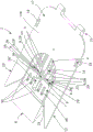
figures 24 to 31 show a charging receiver and a charger plug according to a fourth embodiment,
fig. 32 shows a bottom view of an electric vehicle comprising a charging receiver according to a fourth embodiment,
figure 33 shows a perspective view of a charger plug according to a fourth embodiment,
figure 34 shows an electric vehicle comprising a plurality of charging receivers located at the side, rear or front of the electric vehicle,
fig. 35 to 38 show a charging pile according to the invention.
Detailed Description
Fig. 1A, 1B, 2, 3A, 3B, 4A, 4B, 4C, 5A, 5B, 6A, 6B, 6C, 7A, 7B, 8, 9A, 9B, 10, 11, 13, 15, 16 and 18 show a charger plug 2 for providing electrical energy to an electric vehicle 3, the charger plug 2 comprising at least a first electrical connector 4, a support 17, the first electrical connector 4 comprises at least one first electrical contact 5, the support member 17 comprises a bottom surface 17a and a top surface 17b, the first electrical connector 4 is mounted on the bottom surface 17a, this top surface 17b is arranged to slide on the bottom 3 'of the electric vehicle 3, the first electrical connector 4 is arranged to couple with the corresponding second electrical connector 7 of the charging receptacle 8 located at the bottom 3' of the electric vehicle 3, such that the at least one first electrical contact 5 is electrically connected with the at least one second electrical contact 6 of the second electrical connector 7.
According to the invention, as shown in fig. 3B, 4C, 5B, 6B, 7B, 9B, 10, 11, 13, 15, 16 and 18, the charger plug 2 is characterized in that the support 17 comprises a guiding means 10, 12 comprising a receiving area 14, which receiving area 14 is arranged to at least partially surround the charging receptacle 8 and align the first electrical connector 4 and the second electrical connector 7 when moving the charger plug 2 in the direction of the charging receptacle 8 or vice versa.
The guiding means 10, 12 are arranged to mechanically align the first electrical connector 4 with the second electrical connector 7 of the charging receptacle 8 so that they can be properly connected to charge the battery of the electric vehicle 3 with electrical energy. This automatic alignment between the charger plug 2 and the charging receiver 8 is shown in fig. 4B. These mechanical guiding means 10, 12 are advantageously not damaged by extreme temperatures, rain, snow, ice, external corrosion and/or dust.
More specifically, the top surface 17B can be slid on the bottom 3' of the electric vehicle 3 in the direction of the charging receiver 8 (fig. 4A, 4B, 4C, 5A, 5B) until the guiding means 10, 12 lean against the charging receiver 8 and the receiving area 14 and the portion of the charging receiver 8 with complementary shape are connected together (fig. 6A, 6B, 6C, 10, 11, 15, 16). Alternatively, the bottom 3' of the electric vehicle 3 may be slid on the top surface 17B (fig. 4A, 4B, 4C, 5A, 5B) until the guide means 10, 12 lean against the charging receiver 8 and the receiving area 14 and the portion of the charging receiver 8 with complementary shape are connected together (fig. 7A, 7B, 9A, 9B, 10, 11, 15, 16).
Preferably, the portion of the charging receiver 8 with complementary shape is located on the side of the charging receiver 8 comprising the second contact wall 9 of the second electrical connector 7 (fig. 10, 15 and 17). The receiving area 14 is located at the side of the first contact wall 16 comprising the first electrical connector 4 (fig. 10, 13 and 18). Thus, when the portion of the charging receiver 8 having the complementary shape and the receiving region 14 are connected, the first electrical connector 4 is located in front of the second electrical connector 7. When the charging receiver 8 includes the protective cover 25, the portion having the complementary shape is constituted by a part of the protective cover 25. Then, when the portion of the protective cover 25 is connected with the receiving area 14, the first electrical connector 4 is positioned in front of the protective cover 25, and the second electrical connector 7 is positioned behind the protective cover 25 as long as the protective cover 25 covers the second electrical connector 7. When the protective cover 25 exposes the second electrical connector 7, the first electrical connector 4 is positioned in front of the second electrical connector 7 (fig. 10 and 16).
Preferably, the guiding means comprise a first member 10 projecting from the support 17 on a first lateral side 11 of the first electrical connector 4 and a second member 12 projecting from the support 17 on a second lateral side 13 of the first electrical connector 4, which delimit a first portion 14a and a second portion 14b, respectively, of the receiving area 14, the first member 10 and the second member 12 being positioned at a predetermined distance D from each other and separated from each other by a base portion 14c of the receiving area 14.
Preferably, the receiving area 14 has a U-shape delimited by a first portion 14a, a second portion 14b and a base portion 14c (fig. 10, 11, 13, 15 and 18).
Preferably, the charger plug 2 comprises means 15 for opening the protective cover 25 of the charging receiver 8; 31. 32 arranged in correspondence with the respective means 26 of the charging receiver 8 for opening the protective cover 25; 33. 35 are engaged.
These means 15, 31, 32 for opening the protective cover 25 of the charging receiver 8 are arranged to automatically open the protective cover 25 after the connection between a portion of the protective cover 25 and the receiving area 14, so that the protective cover 25 exposes the second electrical connector 7 to enable the electrical connection between the second electrical contact 6 and the first electrical contact 5. Thus, thanks to the means 26, 33, 35 for opening the protective cover 25, the protective cover 25 is able to protect the second electrical connector 7 from outdoor conditions (as long as it is not connected to the first electrical connector 4) without hindering the subsequent connection with the first electrical connector 4.
In the first preferred embodiment shown in fig. 10, 11 and 13, the means for opening the protective cover 25 are constituted by a protrusion 15 protruding from the receiving area 14 of the support 17, the protrusion 15 being arranged to cooperate with corresponding means for opening the protective cover 25 of the charging receiver 8, the means being constituted by a guide groove 26 of the protective cover 25, the guide groove 26 comprising an inclined wall 27.
The protrusion 15 is provided to lean against the inclined wall 27 when the charger plug 2 and the charging receptacle 8 are moved relative to each other, to rotate the protective cover 25 in the clockwise direction from the first position P1 to the second position P2, thereby exposing the second electrical connector 7.
According to a non-limiting feature of the first embodiment, the projection is constituted by a wheel 15 (fig. 10, 11 and 13).
In a second preferred embodiment, shown in figures 15, 16 and 18, the means for opening the protective cover 25 comprise a first inclined rail 31 and a second inclined rail 32, the first inclined rail 31 projecting from the bottom face 17a of the support 17 and enclosing the first lateral side 11 of the first electrical connector 4, the second inclined rail 32 projecting from the bottom face 17a of the support 17 and enclosing the second lateral side 13 of the first electrical connector 4, the first inclined rail 31 and the second inclined rail 32 being arranged to cooperate respectively with corresponding means for opening the protective cover 25 of the charging receptacle 8, consisting of a first projection 33 projecting from a first lateral wall 34 of the protective cover 25 of the charging receptacle 8 and a second projection 35 projecting from a second lateral wall 36 of the protective cover 25.
These first and second inclined rails 31 and 32 are respectively provided to be inclined against the first and second protrusions 33 and 35 when the charger plug 2 and the charging receptacle 8 are moved relative to each other, so that the protective cover 25 is rotated in the clockwise direction from the first position P1 to the second position P2, thereby exposing the second electrical connector 7.
According to a feature of this second preferred embodiment, the first inclined guide 31 projects perpendicularly to the bottom surface 17a along the first portion 14a of the receiving area 14, and the second inclined guide 32 projects perpendicularly to the bottom surface 17a along the second portion 14b of the receiving area 14.
Preferably, as shown in fig. 10, 11, 13, 15, 16 and 18, the support 17 has a planar shape comprising a bottom surface 17a on which the first electrical connector 4 is mounted and a top surface 17b arranged to slide on the bottom 3' of the electric vehicle 3.
The planar shape is provided to facilitate sliding of the support member 17 with respect to the bottom 3' of the electric vehicle 3.
According to a preferred but not limiting structure of the invention, the support 17 comprises at least one guide wheel 18, 19, as shown in fig. 3B, 4C, 5B, 6C, 7B, 9B, 10, 11 and 13.
The guide wheels 18, 19 are provided to improve the sliding of the charger plug 2 on the bottom 3' of the electric vehicle 3.
According to a feature of the present invention, the first guide wheel 18 and the second guide wheel 19 protrude from the support member 17 through the bottom surface 17a and the top surface 17B, as shown in fig. 3B, 4C, 5B, 6C, 7B, 9B, 10, 11, and 13.
According to another preferred but non-limiting configuration of the invention, as shown in fig. 15, the top surface 17b of the support 17 comprises a plurality of grooves 37, each groove 37 extending along the longitudinal direction of the support 17 and opening into the receiving area 14 through an open end 38, each groove 37 being arranged to receive a respective pin (not shown) protruding from the bottom 3' of the electric vehicle 3.
The plurality of grooves 37 is provided to improve the guidance of the support 17 with respect to the bottom 3' of the electric vehicle 3.
The open end 38 has a funnel shape according to the characteristics of the recess 37.
The funnel shape is arranged to facilitate insertion of the pin into the recess 37.
Preferably, the charger plug 2 comprises a circuit breaker (not shown) electrically connected to at least the first electrical connector 4.
The circuit breaker (e.g. an electrical fuse) is arranged to reduce the short-circuit current in case of an error and to reduce the cross-sectional area of the supply cable of the charging station. Otherwise, even in the case of a medium power charger, a thicker cable is required.
Preferably, the charger plug 2 comprises an inlet fluid connector 43 and an outlet fluid connector 44.
Preferably, the charger plug 2 comprises at least one positioning pin 45.
Preferably, the first electrical connector 4 is a standard connector according to the standard IEC 62196-1/-2/-3.
Fig. 1A to 9B show a charging station 1 comprising at least one arm 20, 20 'connected to a charger plug 2 by a connecting means 21 and comprising at least one actuator 22 to move the at least one arm 20, 20'.
According to the utility model discloses, it includes according to the utility model discloses a charger plug 2 is characterized in that of charging station 1.
Preferably, at least one actuator 22 is arranged to rotate and/or translate at least one arm 20, 20'.
According to a preferred but not limiting structure of the invention, the charging station 1 comprises a first arm 20 and a second arm 20 ', the first arm 20 being connected to the charger plug 2 by means of a connection means 21, the second arm 20' being connected to at least one actuator 22. The first arm 20 and the second arm 20' may be orthogonal (fig. 5A, 5B, 9A and 9B). The actuator 22 may translate the second arm 20'. For example, it may translate in a vertical direction to move the charger plug 2 in the direction of the bottom 3 'of the electric vehicle 3, and/or it may translate along the bottom 3' of the electric vehicle 3.
According to another preferred but non-limiting configuration of the invention, the charging station 1 comprises an arm 20, the arm 20 being connected to the charger plug 2 by means of a connection device 21 and to at least one actuator 22. Actuator 22 may translate and/or rotate arm 20. For example, it may translate in a horizontal direction to move the charger plug 2 outside the first protective housing 23, and/or it may rotate in a clockwise direction to move the charger plug 2 in the direction of the bottom 3 'of the electric vehicle 3, and/or it may translate along the bottom 3' of the electric vehicle 3.
According to a preferred but non-limiting configuration of the present invention, as shown in fig. 1A, 1B, 2, 3A, 4C, 5A, 5B, 6A, 6C, 7A, 7B, 8, 9A and 9B, the charging station 1 includes a first protective housing 23 arranged to protect the charger plug 2 and a second protective housing 24 arranged to protect the actuator 22, the first protective housing 23 and the second protective housing 24 being aligned and spaced apart from each other by a distance D1.
The first protection housing 23 is provided to protect the charger plug 2 from outdoor conditions when the charging station 1 is not in use (fig. 1A, 1B and 2). A second protective housing 24 is provided to protect the actuator 22 from outdoor conditions (fig. 1A-9B).
According to another preferred but non-limiting configuration of the invention, the charging station comprises a single protective casing (not shown) arranged to protect the charger plug 2, the arms 20, 20' and the actuator 22.
Preferably, the charging station 1 comprises at least one power supply system (not shown) to provide electrical energy.
Preferably, the charging station 1 comprises at least one power supply cable (not shown) electrically connected to the charger plug 2, more specifically to the first electrical connector 4 and to the power supply system.
Preferably, the charging station 1 comprises a cooling system (not shown) to keep the battery within an acceptable temperature range during charging.
Preferably, the charging station 1 comprises fluid lines (not shown) connected to the charger plug 2, more particularly to the inlet and outlet fluid connectors and the cooling system.
Figures 1A, 2, 3A, 3B, 4A, 4B, 4C, 5A, 5B, 6A, 6B, 6C, 7A, 7B, 8, 9A, 9B, 10, 11, 12, 15, 16 and 17 show a charging receiver 8 for an electric vehicle 3, which is adapted to be mounted at a bottom 3' of the electric vehicle 3 and arranged to be coupled with a charger plug 2 according to the present invention, the charging receiver 8 comprising at least one second electrical connector 7 arranged to be coupled with the first electrical connector 4 of the charger plug 2, the second electrical connector 7 comprising at least one second electrical contact 6, the second electrical contact 6 being arranged to be electrically coupled with the at least one first electrical contact 5 of the first electrical connector 4 of the charger plug 2, the charging receiver 8 comprising a rotatable protection cover 25, the protection cover 25 being rotatably movable from a first position P1 and a second position P2, the protective cover 25 covers the second electrical connector 7 to protect the second electrical contact 6 in the first position P1, and the protective cover 25 exposes the second electrical connector 7 in the second position P2 to enable electrical connection between the second electrical contact 6 and the first electrical contact 5.
According to the present invention, the charging receiver 8 is characterized in that the protective cover 25 comprises means 26 for opening the protective cover 25; 33. 35, the device 26; 33. 35 are arranged in correspondence with the means 15 for opening the protective cover 25 of the charger plug 2; 31. 32 are engaged such that the protective cover 25 is tilted from the first position P1 to the second position P2.
The protective cover 25 is able to protect the second electrical connector 7 from outdoor conditions when the charging receiver 8 is not in use. These means 26 of the charging receiver 8 for opening the protective cover 25; 33. 35 are arranged to automatically open the protective cover 25 such that the protective cover 25 exposes the second electrical connector 7 to enable a connection between the first electrical connector 4 and the second electrical connector 7.
In a first preferred embodiment shown in fig. 10, 11 and 12, the means for opening the protective cover 25 are constituted by a guide groove 26 of the protective cover 25, which guide groove 26 comprises an inclined wall 27, which inclined wall 27 is arranged to couple with corresponding means for opening the protective cover 25 of the charger plug 2, which means are constituted by a protrusion 15 protruding from the receiving area 14 of the charger plug 2, which guide groove 26 is arranged such that the protective cover 25 is inclined from the first position P1 to the second position P2 when the protrusion 15 engages with the guide groove 26.
The guide groove 26 is provided to receive the protrusion 15 when the charger plug 2 and the charging receptacle 8 are moved relative to each other, and the protrusion 15 may then slide along the inclined wall 27 to rotate the protective cover 25 in the clockwise direction from the first position P1 to the second position P2, and then expose the second electrical connector 7.
According to a feature of this first preferred embodiment, the second contact wall 9 of the second electrical connector 7 comprises an interlocking region 26 'aligned with the guide groove 26 of the protective cover 25, which interlocking region 26' is arranged to couple with the protrusion 15 protruding from the receiving region 14 of the charger plug 2.
The interlocking area 26' is arranged to receive the protrusion 15 after connection between the first electrical connector 4 and the second electrical connector 7.
In a second preferred embodiment, shown in fig. 15, 16 and 17, the means for opening the protective cover 25 comprise a first projection 33 projecting from a first transverse wall 34 of the protective cover 25 and a second projection 35 projecting from a second transverse wall 36 of the protective cover 25, the first projection 33 and the second projection 35 being arranged to cooperate with corresponding means for opening the protective cover 25 of the charger plug 2, which means are constituted by a first inclined rail 31 and a second inclined rail 32, so that the protective cover 25 is inclined from the first position P1 to the second position P2 when the first inclined rail 31 is inclined against and slides on the first projection 33 and the second inclined rail 32 is inclined against and slides on the second projection 35.
These first and second protrusions 33 and 35 are provided to enable the first and second inclined rails 31 and 32 to slide along them when the charger plug 2 and the charging receptacle 8 are moved relative to each other, to rotate the protective cover 25 in the clockwise direction from the first position P1 to the second position P2, and then to expose the second electrical connector 7.
According to features of these first and second preferred embodiments, the protective cover 25 is connected with the second electrical connector 7 by return means to enable the automatic return of the protective cover 25 from the second position P2 to the first position P1 when the protrusion 15 is disengaged from the guide slot 26 or when the first and second inclined rails 31, 32 are released from the first and second protrusions 33, 35, respectively.
In the rest position, the return means are arranged to keep the protective cover 25 in the first position P1 and to automatically return the protective cover 25 to the first position P1 when the protective cover 25 is deflected from the first position P1.
More specifically, when the guide slot 26 receives the projection 15, the projection 15 exerts a force against the return means to stretch it and rotate the protective cover 25 in the clockwise direction to expose the second electrical connector 7. When the projection 15 no longer exerts this force against the return means, the latter returns to its rest position and the protective cover 25 is rotated in the anticlockwise direction to cover the second electrical connector 7.
According to a preferred but non-limiting configuration of the invention, as shown in fig. 10, the second female electrical connector 7 comprises a plurality of recesses 28, each recess 28 comprising one second electrical contact 6, each recess 28 comprising a first opening 29 and a second opening 30, the first opening 29 being located on the second contact wall 9 to engage the first electrical contact 5 of the first male electrical connector 4.
The second opening 30 is provided to discharge dust that may be located in the recess 28 when the first male electrical connector 4 and the second female electrical connector 7 are connected together. In fact, when the first male electrical connector 4 is inserted into the recess 28 through the first opening 29, the first male electrical connector 4 pushes dust in the direction of the second opening 30. Thus, the second electrical contact 6 can be cleaned during connection, which enables a proper contact between the first electrical contact 5 and the second electrical contact 6.
Preferably, the protective cover 25 is pivotably mounted with respect to the axis of the second contact wall 9 of the charging receiver 8.
Preferably, the first and second projections 33 and 35 have a cylindrical shape (fig. 16 and 17).
Preferably, the charging receiver 8 comprises an inlet fluid connector 41 and an outlet fluid connector 40.
Preferably, the charging receiver 8 is adapted to be electrically connected to a battery of the electric vehicle 3.
Preferably, the charging receiver 8 comprises at least one positioning hole 42.
Preferably, the second electrical connector 7 is a standard connector according to the standard IEC 62196-1/-2/-3.
The utility model discloses still relate to one kind and include according to the utility model discloses a charger plug 2 and according to the utility model discloses a charging receiver 8's subassembly.
When the charger plug 2 and the charging receiver 8 are connected together, the first electrical connector 4 of the charger plug 2 is in electrical contact with the second electrical connector 7 of the charging receiver 8.
The invention also relates to a method for connecting a charging receiver 8 of an electric vehicle 3 and a charger plug 2 of a charging station 1, the charging station 1 being located on the ground 39 and adapted to be located below a bottom 3 ' of the electric vehicle 3, the charging station 1 comprising a charger plug 2, at least one arm 20, 20 ' and at least one actuator 22, the charger plug 2 comprising a first electrical connector 4, the arm 20, 20 ' being connected to the charger plug 2 by a connecting means 21, the actuator 22 being adapted to move the at least one arm 20, 20 ', the charging receiver 8 being mounted at the bottom 3 ' of the electric vehicle 3 and comprising a second electrical connector 7, the charger plug 2 comprising a guiding means 10, 12 comprising a receiving area 14, the receiving area 14 being arranged to at least partially surround the charging receiver 8 when the charger plug 2 is moved in the direction of the charging receiver 8 or vice versa, and aligning the first electrical connector 4 and the second electrical connector 7, the method comprising the steps of:
when the charger plug 2 is tilted against the bottom 3' of the electric vehicle 3 in the slide position SP:
A) translating the electric vehicle 3 in a parallel direction with respect to the charger plug 2 to move the charging receptacle 8 in the direction of the charger plug 2, so that the charger plug 2 slides on the bottom 3' of the electric vehicle 3 (fig. 7A, 7B, 8, 9A, 9B), or
B) The arms 20, 20 ' are translated along the bottom 3 ' of the electric vehicle 3 by the actuator 22 to move the charger plug 2 in the direction of the charging receptacle 8, so that the charger plug 2 slides on the bottom 3 ' of the electric vehicle 3 (figures 4A, 4B, 4C, 5A, 5B, 6A, 6B and 6C),
when moving the electric vehicle 3 or the arm 20, 20' according to step a) or B):
C) the first electrical connector 4 and the second electrical connector 7 are aligned by the guiding means 10, 12 of the charger plug 2, and then
D) Tilting the rotatably movable protective cover 25 from a first position P1, in which the protective cover 25 covers the second electrical connector 7 to protect the second electrical contacts 6, to a second position P2, in which the protective cover 25 exposes the second electrical connector 7 via the charging receptacle 8 and the corresponding means 15, 33, 35, 26, 31, 32 of the charger plug 2 for opening the protective cover 25, and then the protective cover 25 is moved from the first position P1 to the second position P2, in which the second electrical connector 7 is exposed
E) The first electrical connector 4 and the second electrical connector 7 are mechanically and electrically connected.
According to step a), the movement of the electric vehicle 3 enables the charging receiver 8 to move in the direction of the charger plug 2 while being guided by the bottom 3' of the electric vehicle 3. Preferably, the electric vehicle 1 can move backward (fig. 7A and 9A) or forward (fig. 8) depending on the relative positions of the charger plug 2 and the charging receiver 8.
According to step B), the movement of the arms 20, 20 'enables the charger plug 2 to move in the direction of the charging receiver 8 while being guided by the bottom 3' of the electric vehicle 3.
According to step C), this alignment enables a suitable connection subsequently to charge the battery of the electric vehicle 3 during charging.
According to step D), this inclination of the protective cover 25 makes it possible to uncover the second electrical connectors 7 only during charging, to protect them from outdoor conditions for the rest of the time.
According to step E), the connection between the first electrical connector 4 and the second electrical connector 7 enables the battery of the electric vehicle to be charged with electrical energy during charging.
According to a preferred but non-limiting embodiment of the invention, when the charger plug 2 and the arms 20, 20' are located in the protection position PP inside a single protection casing (not shown), before steps a) or B) to E):
G) the arms 20, 20 'are translated by the actuator 22 in the vertical direction to move the charger plug 2 in the sliding position SP in the direction of the bottom 3' of the electric vehicle 3, or
H) The arms 20, 20 'are rotated by the actuator 22 to move the charger plug 2 in the direction of the bottom 3' of the electric vehicle 3 at the slide position SP.
According to another preferred but non-limiting embodiment of the invention, when the charger plug 2 is located in the first protective housing 23 in the protective position PP and the arms 20, 20' and the actuator 22 are located in the second protective housing 24, before steps a) or B) to E):
I) the arms 20, 20' are translated by the actuator 22 in a horizontal direction to move the charger plug 2 out of the first protective casing 23 (fig. 1A, 1B, 2, 3A and 3B), and then
K) The arms 20, 20 'are translated by the actuator 22 in the vertical direction to move the charger plug 2 in the sliding position SP in the direction of the bottom 3' of the electric vehicle 3 (fig. 5A and 5B), or
L) the arms 20, 20 'are rotated by the actuator 22 to move the charger plug 2 in the direction of the bottom 3' of the electric vehicle 3 at the slide position SP (fig. 3A, 4A and 4C).
Preferably, the charger plug 2 is arranged according to the above utility model.
Preferably, the charging station 1 is arranged according to the above utility model.
Preferably, the charging receiver 8 is arranged according to the above utility model.
The present invention also relates to a charger plug 202 according to the third embodiment, as shown in fig. 20, 22A to 23B, to supply electric power from a power supply to a battery of an electric vehicle 203. The charger plug 202 comprises at least one first electrical connector 204, the first electrical connector 204 comprising at least first electrical contacts, the first electrical connector 204 being arranged to couple with a corresponding second electrical connector 207 of a charging receiver 208 according to a third embodiment described below, such that the at least first electrical contacts are electrically connected with the corresponding first electrical contacts of the second electrical connector 207, the charger plug 202 comprising at least a first positioning protrusion 209, the first positioning protrusion 209 being arranged to mechanically couple only with a first recess 210 of the charging receiver 208.
The first positioning protrusion 209 is provided to facilitate alignment of the first electrical connector 204 with the second electrical connector of the charging receiver 208.
Preferably, the charger plug 202 comprises a first positioning protrusion 209 and a second positioning protrusion arranged to mechanically couple only with the second recess 210' of the charging receiver 208.
According to a first preferred feature, the first electrical connector 204 comprises a first electrical contact adapted to be electrically connected to a first alternating current line of the electrical power source, a second electrical contact adapted to be electrically connected to a neutral line of the electrical power source and a third electrical contact adapted to be electrically connected to ground.
Preferably, the charger plug 202 according to this first preferred feature is arranged to be connected to a charging receiver 208 described below according to the first preferred feature.
According to a second preferred feature, the first electrical connector 204 comprises a first electrical contact adapted to be electrically connected to a first alternating current line of the electrical power source, a second electrical contact adapted to be electrically connected to a second alternating current line of the electrical power source, a third electrical contact adapted to be electrically connected to a third alternating current line of the electrical power source, a fourth electrical contact adapted to be electrically connected to a neutral line of the electrical power source and a fifth electrical contact adapted to be electrically connected to the earth line.
Preferably, the charger plug 202 according to this second preferred feature is arranged to be connected to a charging receiver 208 described below according to the second preferred feature.
According to a third preferred feature, the first electrical connector 204 comprises a first electrical contact adapted to be electrically connected to a first negative direct current line of the electrical power source, a second electrical contact adapted to be electrically connected to a second positive direct current line of the electrical power source, and a third electrical contact adapted to be electrically connected to ground.
Preferably, the charger plug 202 according to this third preferred feature is arranged to be connected to a charging receiver 208 described below, in particular according to the second or third preferred feature.
Preferably, the first electrical connector 204 includes a first communication contact and a second communication contact.
Preferably, the first electrical connector 204 is a standard connector according to the standard IEC 62196-1/-2/-3.
Preferably, the charger plug 202 includes a third protrusion 214 arranged to exert a force on the protective cover 211 of the charging receiver 208 to move the protective cover 211 from the closed position (fig. 22A and 23A) to the open position (fig. 22B and 23B) of the protective cover 211.
This arrangement enables the protective cover 211 of the charging receiver 208 to be automatically opened when the charger plug 202 is moved in the direction of the charging receiver 208.
The present invention also relates to a charging receiver 208 according to the third embodiment for an electric vehicle 203 including a battery, as shown in fig. 19 to 23B. According to the third embodiment, the charging receiver 208 is adapted to be electrically connected to the battery and is arranged to be coupled with the charger plug 202, the charging receiver 208 comprises at least a second electrical connector 207 arranged to be coupled with the first electrical connector 204 of the charger plug 202, the second electrical connector 207 comprises at least a first electrical contact arranged to be electrically coupled with a corresponding first electrical contact of the first electrical connector 204 of the charger plug 202, the charging receiver 208 comprises at least one first recess 210, 210 'arranged to be mechanically coupled only with the first positioning protrusion 209 of the charger plug 202, the first recess 210, 210' having a funnel shape.
This particular funnel shape is provided to facilitate insertion of the first locating protrusion 209, thereby facilitating alignment of the first electrical connector 204 with the second electrical connector of the charging receiver 208.
Preferably, the charging receiver 208 comprises a first recess 210 and a second recess 210 ', the second recess 210 ' being arranged to mechanically couple only with the second positioning protrusion of the charger plug 202, the second recess 210 ' having a funnel shape.
According to a first preferred feature, the second electrical connector 207 comprises a first electrical contact adapted to be electrically connected to a first alternating current line electrically connected to the battery, a second electrical contact adapted to be electrically connected to a neutral line electrically connected to the battery, and a third electrical contact adapted to be electrically connected to ground.
Preferably, the charging receiver 208 according to this first preferred feature is arranged to be connected to the charger plug 202 according to the first preferred characteristic.
According to a feature of this first preferred characteristic, the second electrical connector 207 comprises a fourth electrical contact adapted to be electrically connected to a first negative direct current line electrically connected to the battery, and a fifth electrical contact adapted to be electrically connected to a second positive direct current line electrically connected to the battery.
Preferably, the charging receiver 208 according to this feature of the first preferred feature is arranged to be connected to the charger plug 202 according to the first preferred feature or the third preferred feature.
According to a second preferred feature, the second electrical connector 207 comprises a first electrical contact adapted to be electrically connected to a first alternating current line electrically connected to the battery, a second electrical contact adapted to be electrically connected to a second alternating current line electrically connected to the battery, a third electrical contact adapted to be electrically connected to a third alternating current line electrically connected to the battery, a fourth electrical contact adapted to be electrically connected to a neutral line electrically connected to the battery, and a fifth electrical contact adapted to be electrically connected to ground.
Preferably, the charging receiver 208 according to this second preferred feature is arranged to be connected to the charger plug 202 according to the second preferred characteristic.
According to a feature of this second preferred feature, the second electrical connector 207 comprises a sixth electrical contact adapted to be electrically connected to a first negative direct current line electrically connected to the battery, and a seventh electrical contact adapted to be electrically connected to a second positive direct current line electrically connected to the battery.
Preferably, the charging receiver 208 according to this feature of the second preferred feature is arranged to be connected to the charger plug 202 according to the second preferred feature or the third preferred feature.
According to a third preferred feature, the second electrical connector 207 comprises a first electrical contact adapted to be electrically connected to a first negative direct current line electrically connected to the battery, a second electrical contact adapted to be electrically connected to a second positive direct current line electrically connected to the battery, and a third electrical contact adapted to be electrically connected to ground.
Preferably, the charging receiver 208 according to this third preferred feature is arranged to be connected to the charger plug 202 according to the third preferred characteristic.
Preferably, the second electrical connector 207 comprises a first communication contact and a second communication contact.
Preferably, the second electrical connector 207 is a standard connector according to the standard IEC 62196-1/-2/-3.
According to a first possibility, illustrated in fig. 22A and 22B, charging receiver 208 comprises a protective cover 211 comprising a first portion 211a and a second portion 211B, second portion 211B being connected to charging receiver 208 by return means 212, protective cover 211 being rotatably movable between a closed position (fig. 22A) in which first portion 211a of protective cover 211 covers at least second electrical connector 207, and an open position (fig. 22B) in which first portion 211a of protective cover 211 exposes at least second electrical connector 207, return means 212 being arranged to hold protective cover 211 in the closed position, protective cover 211 being arranged to move from the closed position to the open position when a force F is exerted on second portion 211B of protective cover 211.
According to a second possibility, illustrated in fig. 23A and 23B, charging receiver 208 comprises a protective cover 211 comprising a first portion 211a and a second portion 211B, second portion 211B being connected to charging receiver 208 by return means 212, protective cover 21 being movable in translation between a closed position (fig. 23A) in which first portion 211a of protective cover 211 covers at least second electrical connector 207, and an open position (fig. 23B) in which opening 231 of first portion 211a of protective cover 211 exposes at least second electrical connector 207, return means 212 being arranged to hold protective cover 211 in the closed position, protective cover 211 being arranged to move from the closed position to the open position when a force F is exerted on second portion 211B of protective cover 211.
According to a first and a second possibility, a protective cover 211 is provided to protect the second electrical connector 207 from outdoor conditions. In addition, when the charger plug 202 moves in the direction of the charging receiver 208 and a force F is applied to the second portion 211b of the protective cover 211 by the third protrusion 214, the protective cover 211 can be automatically opened.
The utility model discloses still relate to a charging station, as shown in fig. 24 to 33. The charging station includes the charger plug 102 according to the fourth embodiment to supply electric power to the electric vehicle 103. This charger plug 102 comprises a first electrical connector 104 comprising a first electrical contact 105, a second electrical contact 105 ', a third electrical contact 105", the first electrical connector 104 being arranged to couple with a respective second electrical connector 107 of a charging receptacle 108 according to a fourth embodiment located under the electric vehicle 3, such that the first, second and third electrical contacts 105, 105 ', 105" are electrically connected with respective fourth, fifth, sixth electrical contacts 106, 106 ', 106 "of the second electrical connector 107, the first electrical connector 104 having a trapezoidal cross-section and comprising an upper portion 109 with the first electrical contact 105, a first transverse portion 110 with the second electrical contact 105 ' and a second transverse portion 111 with the third electrical contact 105 ', the first electrical contact 105, the second electrical contact 105 ' and the third electrical contact 105 ' being separated and insulated from each other by an insulating core 112.
According to a preferred feature, as shown in figures 25, 28 and 29, the charger plug 102 comprises a support 113 supporting the first electrical connector 104, the first electrical connector 104 being fixed to the support 113.
According to another preferred feature, as shown in fig. 26 and 27, the charger plug 102 comprises a support 113 supporting the first electrical connector 104, the first electrical connector 104 being connected to the support 113 by return means 114.
According to these features and those of the fourth embodiment, as shown in figures 24, 26, 28, 30 and 31, the upper portion 109 comprising the first electrical contact 105 is connected to the insulating core 112 by return means 115.
The return means 115 are arranged to ensure that the first electrical contact 105 is in contact with a corresponding fourth electrical contact 106 of the charging receiver 108, which fourth electrical contact 106 is not necessarily connected to the upper portion 126 by the return means 127.
Preferably, as shown in fig. 30 and 31, the charging station comprises a protective housing 116 arranged to protect the charger plug 102 and a telescopic arm or scissor lift connected to the first electrical connector 104, which is movable between a protective position (fig. 30) in which the first electrical connector 104 is enclosed within the protective housing 116, and an operating position (fig. 31) in which the first electrical connector 104 protrudes outside the protective housing 116.
Preferably, the protective housing 116 comprises a first protective cover 118 arranged to be movable between a closed position and an open position (fig. 31), the first protective cover 118 being arranged to move from the closed position to the open position when the first electrical connector 104 of the charger plug 102 is tilted against the first protective cover 118, more particularly when the upper portion 119 is tilted against the first protective cover 118.
The first protective cover 118 is configured to protect the first electrical connector 104 from outdoor conditions. In addition, the first protective cover 118 may automatically open when the charger plug 102 moves in the direction of the charging receiver 108.
Preferably, the first protective cover 118 includes a first cleaning device 119.
These cleaning means 119 are arranged to wipe the first, second and third electrical contacts 105, 105' of the first electrical connector 104 to remove dust and corrosion.
Preferably, the cleaning device 119 is constructed of a rough or sharp-edged material, such as a hard plastic, a metal scrubber, or a brush-like material, such as a metal brush, a hard fiber brush.
The present invention relates to a charging receiver 108 according to a fourth embodiment for an electric vehicle 103, which is adapted to be located below the electric vehicle 103 and arranged to be coupled with a charger plug 102 according to the fourth embodiment of a charging station as shown in fig. 24 to 32, as shown in fig. 24 to 32. The charging receiver 108 comprises a second electrical connector 107 arranged to be connected with the first electrical connector 104 of the charger plug 102, the second electrical connector 107 comprising fourth, fifth, sixth electrical contacts 106, 106 ', 106 "arranged to be electrically connected with the respective first, second, third electrical contacts 105, 105 ', 105" of the first electrical connector 104 of the charger plug 102, the second electrical connector 107 comprising a recess 120 in which recess 120 the fourth, fifth, sixth electrical contacts 106, 106 ', 106 "are located, the recess 120 comprising a receiving opening 121 to allow insertion of the first electrical connector 104 of the charger plug 102.
According to a first possibility, the recess 120 has a trapezoidal section, as shown in fig. 24 to 27, 30, 31 and 33.
Preferably, as shown in fig. 24 and 25, the recess 120 has a trapezoidal section, comprising a first transverse portion 122, and comprising a second transverse portion 123, the first transverse portion 122 comprising the fifth electrical contact 106' connected to the first transverse portion 122 by return means 124, the second transverse portion 123 comprising the sixth electrical contact 106 ″ connected to the second transverse portion 123 by return means 125.
The return means 124, 125 are provided to ensure that the fifth electrical contact 106 'is in contact with the corresponding second electrical contact 105' of the charger plug 102 and the sixth electrical contact 106 "is in contact with the corresponding third electrical contact 105" of the charger plug 102, respectively.
Preferably, as shown in fig. 25, 26 and 27, the recess 120 has a trapezoidal section comprising an upper portion 126, the upper portion 126 comprising the fourth electrical contact 106, the fourth electrical contact 106 being connected to the upper portion 126 by a return means 127.
The return means 127 are provided to ensure that the fourth electrical contact 106 is in contact with the corresponding first electrical contact 105 of the charger plug 102, which first electrical contact 105 is not necessarily connected to the insulating core 112 by the return means 115.
According to a second possibility, the recess 120 has a rectangular section, as shown in fig. 28 and 29.
Preferably, as shown in fig. 28 and 29, the recess 120 has a rectangular cross section, comprises a first transverse portion 122, and comprises a second transverse portion 123, the first transverse portion 122 comprising the fifth electrical contact 106' connected to the first transverse portion 122 by return means 124, and the second transverse portion 123 comprising the sixth electrical contact 106 ″ connected to the second transverse portion 123 by return means 125.
The return means 124, 125 are provided to ensure that the fifth electrical contact 106 'is in contact with the corresponding second electrical contact 105' of the charger plug 102 and the sixth electrical contact 106 "is in contact with the corresponding third electrical contact 105" of the charger plug 102, respectively.
Preferably, as shown in fig. 28 and 29, the recess 120 has a trapezoidal section comprising an upper portion 126, the upper portion 126 comprising the fourth electrical contact 106, the fourth electrical contact 106 being connected to the upper portion 126 by a return means 127.
The return means 127 are provided to ensure that the fourth electrical contact 106 is in contact with the corresponding first electrical contact 105 of the charger plug 102, which first electrical contact 105 is not necessarily connected to the insulating core 112 by the return means 115.
Preferably, according to the present invention, the charging receptacle 108 comprises a second protection cover 128, which is movable from a closed position, in which the second protection cover 128 covers the receiving opening 121 to protect the second electrical connector 107 (fig. 30), to an open position, in which the second protection cover 128 exposes the receiving opening 121, the second protection cover 128 being connected to the recess 120 by a return means, such that the second protection cover 128 is arranged to be moved from the closed position to the open position when the first electrical connector 104 of the charger plug 102 is tilted against the second protection cover 128.
The second protective cover 128 is configured to protect the second electrical connector 107 from outdoor conditions. In addition, the second protective cover 128 may be automatically opened when the charger plug 102 moves in the direction of the charging receiver 108.
Preferably, the second protective cover 128 or the receiving opening 121 comprises second cleaning means 129.
These second cleaning means 129 are arranged to wipe the first, second and third electrical contacts 105, 105', 105 "of the first electrical connector 104 to remove dust and corrosion.
Preferably, the cleaning device 129 is constructed of a rough or sharp-edged material, such as a hard plastic, metal scrubber, or brush-like material, such as a metal brush, a hard fiber brush.
Another object of the present invention relates to a charging pile 300, as shown in fig. 35 to 38. The charging post 300 comprises at least one parking space 301 and a charging station 302, which charging station 302 comprises a charger plug 303 to provide electrical energy at least to a charging receiver 304 of an electric vehicle 305. Charging station 302 comprises a base 306 extending upwardly relative to a ground 307 of parking space 301 and a linear actuator 308, which linear actuator 308 comprises a first end 309 and a second end 310 mounted on said base 306, where charger plug 303 is mounted, said linear actuator 308 being inclined relative to base 306 and forming an angle α with respect to ground 307 which is equal to the angle of inclination of charging receiver 304 with respect to ground 307.
Preferably, the charging station 302 includes an auxiliary control unit (not shown) that includes an auxiliary communication module (not shown) to communicate with a main communication module (not shown) of a main control unit (not shown) of the electric vehicle 305.
These primary and secondary communication modules are arranged to exchange data between the charging post 300 and the electric vehicle 305.
Preferably, the primary communication module and the secondary communication module may be any type of wireless communication device, such as: a bluetooth unit or an RFID unit or an NFC unit or a Wi-Fi unit.
Preferably, parking space 301 comprises at least one reference element (not shown).
Preferably, the reference element may be located on a base 306, the charger plug 303 being mounted on the base 306.
Preferably, the reference element may be an active distance sensor or a reflector panel/area.
The reference element is arranged to assist the main control unit of the electric vehicle 305 to measure the distances d1, d2 between the charging receiver 304 and the base 306.
Preferably, the linear actuator 308 is constituted by a telescopic arm.
The charging pile 300 is arranged to enable a method according to another object of the invention described below.
Another object according to the present invention relates to a method for positioning an electric vehicle 305 as shown in fig. 34 on a charging pile 300 as described above and as shown in fig. 35 to 38. The electric vehicle 305 includes at least one sensor (not shown) and a main control unit (not shown) including a main communication module (not shown). The charging post 300 comprises at least one parking space 301 and a charging station 302, which charging station 302 comprises a charger plug 303 to provide electrical energy at least to a charging receiver 304 of an electric vehicle 305. The charging station 302 comprises a base 306 extending upwards with respect to a ground 307 of the parking space 301 and a linear actuator 308, the linear actuator 308 comprising a first end 309 and a second end 310 mounted on said base 306, where the charger plug is mounted, said linear actuator 308 being inclined with respect to the base 306 and forming an angle a with respect to the ground 307 which is equal to the inclination angle of the charging receiver 304 with respect to the ground 307, the charging station 302 comprising an auxiliary control unit comprising an auxiliary communication module communicating with a main communication module of a main control unit of the electric vehicle 305. The charger plug 303 is capable of mating with a charging receiver 304 of an electric vehicle 305.
According to the utility model discloses, this method includes following step:
the electric vehicle 305 is moved to the parking space 301, to reach the parking position,
knowing the height h1, h2 of the charging receiver 304, the height of the second end 310 and the angle α, the aligned position of the electric vehicle 305, in which the charging receiver 304 and the charger plug 303 are aligned, is determined by determining at least one reference distance d1, d2 between the charging receiver 304 and the base 306.
The electric vehicle 305 on the parking space 301 is moved from the parking position to the aligned position by at least one sensor of the electric vehicle 305 measuring the actual distances d1, d2 between the charging receiver 304 and the base 306, which actual distances d1, d2 are compared with the predetermined reference distances d1, d2 by the main control unit to park the electric vehicle 305 at the predetermined reference distances d1, d2 (fig. 35 and 37).
The heights h1, h2 of the charging receiver 304 may be different depending on the model of the electric vehicle 305. For example, fig. 35 and 36 show the electric vehicle 305 having the height h1 of the charging receiver 304, which is h1 smaller than the height h2 of the charging receiver 304 of the electric vehicle 305 shown in fig. 37 and 38. In this case, it is known in the art to use robots to align the charger plug of the charging station with the charging receiver 304 of the electric vehicle 305. According to the present invention, the angle α of the charging receiver 304 is standardized, i.e. independent of the height h1, h2 of the charging receiver 304. Therefore, when the heights h1, h2 of the charging receiver 304 of one electric vehicle 305 are different from the other electric vehicle 305, it is only necessary to park the electric vehicle 305 at the distances d1, d2 corresponding to the predetermined reference distances d1, d2 to align the charging receiver 304 and the charger plug 303. Advantageously, according to the present invention, no expensive and complicated robots are required.
Preferably, the main control unit of the electric vehicle 305 is electrically connected to at least one sensor of the electric vehicle 305.
Preferably, the main control unit is also adapted and arranged to control at least one sensor of the electric vehicle 305 and to collect data representative of the actual distances d1, d2 of the sensor.
Preferably, the main control unit is also adapted and arranged to automatically move the electric vehicle 305.
According to the first embodiment, knowing the heights h1, h2 of the charging receiver 304, the height of the second end 310, and the angle α, the main control unit of the electric vehicle 305 determines the reference distances d1, d2 between the charging receiver 304 and the base 306 when determining the alignment position.
According to a feature of this first embodiment, the secondary communication module sends data regarding the height of the second end 310 to the primary communication module before determining the alignment position.
According to the second embodiment, knowing the heights h1, h2 of the charging receiver 304, the height of the second end 310, and the angle α, the auxiliary control unit of the electric vehicle determines the reference distances d1, d2 between the charging receiver 304 and the base 306 when determining the alignment position.
According to a feature of this second embodiment, the primary communication module transmits data about the heights h1, h2 to the secondary communication module before the determination of the alignment position and the secondary communication module transmits data about the reference distances d1, d2 to the primary communication module after the determination of the alignment position.
Preferably, when moving the electric vehicle 305 to the aligned position, the electric vehicle 305 measures the actual distances d1, d2 between the reference elements located on the base 306.
Preferably, the method further comprises the step of translating the linear actuator 308 along the direction D of the charging receiver 304 when the electric vehicle 305 is in the aligned position (fig. 36 and 38).
Preferably, the method further comprises the step of sending a signal from the main control unit to the secondary control unit to trigger translation of the linear actuator 308 when the electric vehicle 305 is in the aligned position.
Preferably, the signal is constituted by an electromagnetic signal arranged to communicate wirelessly.
Of course, the invention is not limited to the embodiments described and shown in the drawings. Modifications are possible without going beyond the scope of protection of the invention, in particular from the point of view of the composition of the various elements or by replacing technical equivalents.
Claims (24)
1. Charger plug (2) for providing electrical energy to an electric vehicle (3), the charger plug (2) comprising at least a first electrical connector (4), a support (17), the first electrical connector (4) comprising at least one first electrical contact (5), the support (17) comprising a bottom face (17a) and a top face (17b), the first electrical connector (4) being mounted on the bottom face (17a), the top face (17b) being arranged to slide on a bottom (3 ') of the electric vehicle (3), the first electrical connector (4) being arranged to couple with a corresponding second electrical connector (7) of a charging receptacle (8) located at the bottom (3') of the electric vehicle (3) such that the at least one first electrical contact (5) is electrically connected with at least one second electrical contact (6) of the second electrical connector (7),
characterized in that, in the charger plug (2), the support (17) comprises a guiding means (10, 12), the guiding means (10, 12) comprising a receiving area (14), the receiving area (14) being arranged to at least partially surround the charging receptacle (8) and being arranged to align the first electrical connector (4) and the second electrical connector (7) when moving the charger plug (2) in the direction of the charging receptacle (8) or vice versa.
2. Charger plug according to claim 1, wherein the guiding means comprise a first member (10) projecting from the support (17) on a first lateral side (11) of the first electrical connector (4) and a second member (12) projecting from the support (17) on a second lateral side (13) of the first electrical connector (4), the first member (10) and the second member (12) delimiting a first portion (14a) and a second portion (14b) of the receiving area (14), respectively, the first member (10) and the second member (12) being positioned at a predetermined distance from each other and being separated from each other by a base (14c) of the receiving area (14).
3. Charger plug according to claim 2, wherein the receiving area (14) has a U-shape delimited by the first portion (14a), the second portion (14b) and the base (14 c).
4. Charger plug according to any one of claims 2 to 3, wherein the charger plug (2) comprises means (15; 31, 32) for opening the protective cover (25) of the charging receiver (8), which means (15; 31, 32) for opening the protective cover (25) of the charging receiver (8) are arranged to cooperate with corresponding means (26; 33, 35) for opening the protective cover (25) of the charging receiver (8).
5. Charger plug according to claim 4, wherein the means for opening the protective cover (25) are constituted by a protrusion (15) protruding from the receiving area (14) of the support (17), the protrusion (15) being arranged to cooperate with the respective means for opening the protective cover (25) of the charging receiver (8), the respective means for opening the protective cover (25) of the charging receiver (8) being constituted by a guide slot (26) of the protective cover (25), the guide slot (26) comprising an inclined wall (27).
6. Charger plug according to claim 4, wherein the means for opening the protective cover (25) comprise a first inclined rail (31) and a second inclined rail (32), the first inclined rail (31) protruding from the bottom face (17a) of the support (17) and surrounding the first lateral side (11) of the first electrical connector (4), the second inclined rail (32) protruding from the bottom face (17a) of the support (17) and surrounding the second lateral side (13) of the first electrical connector (4), the first inclined rail (31) and the second inclined rail (32) being arranged to cooperate with the respective means for opening the protective cover (25) of the charging receiver (8), respectively, the respective means for opening the protective cover (25) of the charging receiver (8) being formed by the protective cover (8) protruding from the charging receiver (8) A first projection (33) projecting from a first transverse wall (34) of the cover (25) and a second projection (35) projecting from a second transverse wall (36) of the protective cover (25).
7. Charger plug according to claim 6, wherein the first inclined rail (31) projects perpendicularly to the bottom face (17a) along the first portion (14a) of the receiving area (14), and the second inclined rail (32) projects perpendicularly to the bottom face (17a) along the second portion (14b) of the receiving area (14).
8. Charger plug according to claim 1, wherein the support (17) has a planar shape comprising the bottom face (17a) and the top face (17b), the first electrical connector (4) being mounted on the bottom face (17a), the top face (17b) being arranged to slide on the bottom (3') of the electric vehicle (3).
9. Charger plug according to claim 1, wherein the support (17) comprises at least one guiding wheel (18, 19).
10. Charger plug according to claim 9, wherein a first guide wheel (18) and a second guide wheel (19) protrude from the support (17) through the bottom face (17a) and the top face (17 b).
11. Charger plug according to claim 1, wherein the top surface (17b) of the support (17) comprises a plurality of grooves (37), each groove (37) extending along the longitudinal direction of the support (17) and opening into the receiving area (14) through an open end (38), each groove (37) being arranged to receive a respective pin protruding from the bottom (3') of the electric vehicle (3).
12. The charger plug as recited in claim 11, wherein the open end (38) has a funnel shape.
13. Charger plug according to claim 1, wherein the charger plug (2) comprises a circuit breaker electrically connected to at least a first electrical connector (4).
14. A charging station comprising at least one arm (20, 20 ') connected to a charger plug (2) by a connecting device (21) and comprising at least one actuator (22) to move said at least one arm (20, 20'), characterized in that it comprises a charger plug (2) according to any one of claims 1 to 13.
15. The charging station according to claim 14, wherein the at least one actuator (22) is arranged to rotate and/or translate the at least one arm (20, 20').
16. The charging station according to any one of claims 14 to 15, wherein the charging station (1) comprises a first protective housing (23) arranged to protect the charger plug (2) and a second protective housing (24) arranged to protect the actuator (22), the first protective housing (23) and the second protective housing (24) being aligned and spaced apart from each other by a distance D1.
17. The charging station according to any of claims 14 to 15, wherein the charging station (1) comprises a single protective housing arranged to protect the charger plug (2), the arm (20, 20') and the actuator (22).
18. A charging receptacle (8) for an electric vehicle (3), the charging receptacle (8) being adapted to be mounted at a bottom (3') of the electric vehicle (3) and being arranged to be coupled with a charger plug (2) according to any one of claims 1 to 13, the charging receptacle (8) comprising at least one second electrical connector (7), the second electrical connector (7) being arranged to be coupled with the first electrical connector (4) of the charger plug (2), the second electrical connector (7) comprising at least one second electrical contact (6), the second electrical contact (6) being arranged to be electrically connected with at least one first electrical contact (5) of the first electrical connector (4) of the charger plug (2), the charging receptacle (8) comprising a rotatable protective cover (25), the protective cover (25) being rotatably movable from a first position (P1) and a second position (P2), in the first position (P1) the protective cover (25) covers the second electrical connector (7) to protect the second electrical contact (6), in the second position (P2) the protective cover (25) exposes the second electrical connector (7) to enable electrical connection of the second electrical contact (6) and the first electrical contact (5),
characterized in that in the charging receiver (8), the protective cover (25) comprises means (26; 33, 35) for opening the protective cover (25), the means (26; 33, 35) for opening the protective cover (25) being arranged to tilt the protective cover (25) from the first position (P1) to the second position (P2) when mated with corresponding means (15; 31, 32) for opening the protective cover (25) of the charger plug (2).
19. A charging receiver according to claim 18, wherein the means for opening the protective cover (25) are constituted by a guide slot (26) of the protective cover (25), the guide slot (26) comprising an inclined wall (27), the inclined wall (27) being arranged to couple with the respective means for opening the protective cover (25) of the charger plug (2), the respective means for opening the protective cover (25) of the charger plug (2) being constituted by a protrusion (15) protruding from a receiving area (14) of the charger plug (2), the guide slot (26) being arranged such that the protective cover (25) is inclined from the first position (P1) to the second position (P2) when the protrusion (15) is engaged with the guide slot (26).
20. The charging receiver according to claim 19, wherein the second contact wall (9) of the second electrical connector (7) comprises an interlocking region (26 ') aligned with the guide slot (26) of the protective cover (25), the interlocking region (26') being arranged to couple with the protrusion (15) protruding from the receiving region (14) of the charger plug (2).
21. Charging receiver according to claim 18, wherein the means for opening the protective cover (25) comprise a first projection (33) projecting from a first lateral wall (34) of the protective cover (25) and a second projection (35) projecting from a second lateral wall (36) of the protective cover (25), the first projection (33) and the second projection (35) being arranged to cooperate with the respective means for opening the protective cover (25) of the charger plug (2), the respective means for opening the protective cover (25) of the charger plug (2) being constituted by a first inclined rail (31) and a second inclined rail (32), such that when the first inclined rail (31) is inclined against the first projection (33) and slides on the first projection (33) and the second inclined rail (32) is inclined against the second projection (35) and slides on the second projection (35) When the protective cover (25) is tilted from the first position (P1) to the second position (P2).
22. The charging receiver according to claim 19 or 20, wherein the protective cover (25) is connected with the second electrical connector (7) by return means to return the protective cover (25) from the second position (P2) to the first position (P1) when the protrusion (15) is disengaged from the guide slot (26).
23. The charging receiver according to claim 21, wherein the protective cover (25) is connected with the second electrical connector (7) by return means to return the protective cover (25) from the second position (P2) to the first position (P1) when the first and second inclined rails (31, 32) are released from the first and second protrusions (33, 35), respectively.
24. Charging receiver according to claim 20, wherein the female second electrical connector (7) comprises a plurality of recesses (28), each recess (28) comprising one of the second electrical contacts (6), each recess (28) comprising a first opening (29) and a second opening (30), the first opening (29) being located on the second contact wall (9) to engage the first electrical contact (5) of the male first electrical connector (4).
Applications Claiming Priority (2)
| Application Number | Priority Date | Filing Date | Title |
|---|---|---|---|
| EP18305428.7 | 2018-04-10 | ||
| EP18305428.7A EP3552862B1 (en) | 2018-04-10 | 2018-04-10 | Charger plug for supplying electric energy to an electric vehicle, charging station comprising said charger plug, charging receiver for an electric vehicle and method for connecting said charging receiver and said charger plug |
Publications (1)
| Publication Number | Publication Date |
|---|---|
| CN211969196U true CN211969196U (en) | 2020-11-20 |
Family
ID=61972473
Family Applications (1)
| Application Number | Title | Priority Date | Filing Date |
|---|---|---|---|
| CN201920483824.7U Active CN211969196U (en) | 2018-04-10 | 2019-04-10 | Charger plug, charging station and charging receiver of electric vehicle |
Country Status (5)
| Country | Link |
|---|---|
| EP (1) | EP3552862B1 (en) |
| CN (1) | CN211969196U (en) |
| AU (1) | AU2019202467A1 (en) |
| ES (1) | ES2873941T3 (en) |
| PL (1) | PL3552862T3 (en) |
Cited By (1)
| Publication number | Priority date | Publication date | Assignee | Title |
|---|---|---|---|---|
| US20220126718A1 (en) * | 2020-10-28 | 2022-04-28 | GM Global Technology Operations LLC | System and method of autonomously charging an electric vehicle |
Families Citing this family (8)
| Publication number | Priority date | Publication date | Assignee | Title |
|---|---|---|---|---|
| EP3835113B1 (en) | 2019-12-10 | 2023-08-09 | Hager-Electro Sas | Connecting assembly for supplying electric energy from a ground charging station to a vehicle |
| CN111619377B (en) * | 2020-05-27 | 2022-06-17 | 惠州市英盟科技有限公司 | Electric vehicle high-power charger capable of effectively preventing water in outdoor use and method |
| JP7225168B2 (en) * | 2020-07-31 | 2023-02-20 | 矢崎総業株式会社 | Vehicle charging system and power receiving fitting |
| JP2022056840A (en) * | 2020-09-30 | 2022-04-11 | 新東工業株式会社 | Charging system and information processing device |
| CN114435160A (en) * | 2020-10-30 | 2022-05-06 | 大陆工程服务有限公司 | Method for operating a charging robot |
| CN112455260B (en) * | 2020-11-12 | 2022-07-12 | 武汉合康智能电气有限公司 | Charging conversion platform and charging system |
| CN113085613A (en) * | 2021-04-07 | 2021-07-09 | 张文龙 | Electric automobile charge and discharge facility based on smart power grids |
| DE102021209672A1 (en) | 2021-09-02 | 2023-03-02 | Psa Automobiles Sa | Charging socket with lockable flap on an electric vehicle |
Family Cites Families (6)
| Publication number | Priority date | Publication date | Assignee | Title |
|---|---|---|---|---|
| DE102009001080A1 (en) * | 2009-02-23 | 2010-08-26 | Robert Bosch Gmbh | Autonomous charging device for Plugln hybrid vehicles |
| FR2968245B1 (en) * | 2010-12-02 | 2012-12-21 | Renault Sas | DEVICE FOR SUPPORTING FLOOR RECOVERY OF AN ELECTRIC VEHICLE |
| DE102012007713B4 (en) * | 2011-04-20 | 2015-03-19 | SALT AND PEPPER Holding GmbH & Co. KG | Apparatus for electrically charging electrically driven road vehicles |
| JP6144829B2 (en) * | 2013-06-20 | 2017-06-07 | ボルボトラックコーポレーション | Protective structure for electric vehicle |
| US9527403B2 (en) | 2014-04-29 | 2016-12-27 | Tesla Motors, Inc. | Charging station providing thermal conditioning of electric vehicle during charging session |
| US9428070B2 (en) * | 2014-07-24 | 2016-08-30 | Ford Global Technologies, Llc | Hands free vehicle charging system |
-
2018
- 2018-04-10 PL PL18305428T patent/PL3552862T3/en unknown
- 2018-04-10 ES ES18305428T patent/ES2873941T3/en active Active
- 2018-04-10 EP EP18305428.7A patent/EP3552862B1/en active Active
-
2019
- 2019-04-09 AU AU2019202467A patent/AU2019202467A1/en active Pending
- 2019-04-10 CN CN201920483824.7U patent/CN211969196U/en active Active
Cited By (2)
| Publication number | Priority date | Publication date | Assignee | Title |
|---|---|---|---|---|
| US20220126718A1 (en) * | 2020-10-28 | 2022-04-28 | GM Global Technology Operations LLC | System and method of autonomously charging an electric vehicle |
| US11427102B2 (en) * | 2020-10-28 | 2022-08-30 | GM Global Technology Operations LLC | System and method of autonomously charging an electric vehicle |
Also Published As
| Publication number | Publication date |
|---|---|
| ES2873941T3 (en) | 2021-11-04 |
| AU2019202467A1 (en) | 2019-10-24 |
| EP3552862B1 (en) | 2021-03-31 |
| EP3552862A1 (en) | 2019-10-16 |
| PL3552862T3 (en) | 2021-11-08 |
Similar Documents
| Publication | Publication Date | Title |
|---|---|---|
| CN211969196U (en) | Charger plug, charging station and charging receiver of electric vehicle | |
| US10017062B2 (en) | Electric charging device, electric connection device, system and method for charging a battery of a vehicle | |
| US7064519B2 (en) | Battery charger with improved terminal protection | |
| US5584715A (en) | Universal electrical connector for receiving DC and AC electrical connectors | |
| EP2843773B1 (en) | Connector device | |
| EP2988375B1 (en) | Connector device | |
| CN111902309B (en) | Motor vehicle with an electrical contact-and-conduction unit | |
| CN112615216A (en) | Power connector system | |
| US11864720B2 (en) | Rechargeable battery for powering a vacuum cleaner | |
| CN107406008B (en) | Data transmission device and device for the conductive transmission of electrical energy | |
| CN101807768A (en) | Power connector with integrated signal connector | |
| CN105229866A (en) | With the connector assembly of socket carrier | |
| CN112550017A (en) | Energy supply device and method for operating an energy supply device | |
| US20200139820A1 (en) | System and Method for Automatic Connector Coupling for an Electric Vehicle | |
| CN100377440C (en) | Connector structure | |
| US20220224048A1 (en) | Automatic coupler assembly | |
| CN112937347A (en) | Connection assembly for supplying electric energy to a vehicle from a ground charging station | |
| CN103366991B (en) | For the manufacture of the method for thermally sensitive electric switch with the housing forming movable unit with pin guide | |
| CN211684687U (en) | Mechanical device for charging station | |
| CN110509795B (en) | Automatic charging method and device for mobile trolley and plug-in type charging male head assembly | |
| CN210040639U (en) | Charger plug and charging receiver | |
| CN103098312A (en) | Electrical device, in particular a socket and connector, having a secondary lock, method for moulding such a device and mould for producing such a device | |
| EP2981432B1 (en) | Connecting apparatus for connecting an electrically powered vehicle to a charging station | |
| JP2021028876A (en) | connector | |
| CN217227311U (en) | Movable platform system |
Legal Events
| Date | Code | Title | Description |
|---|---|---|---|
| GR01 | Patent grant | ||
| GR01 | Patent grant |