CN211808016U - Plastic film wringing machine - Google Patents
Plastic film wringing machine Download PDFInfo
- Publication number
- CN211808016U CN211808016U CN202020200416.9U CN202020200416U CN211808016U CN 211808016 U CN211808016 U CN 211808016U CN 202020200416 U CN202020200416 U CN 202020200416U CN 211808016 U CN211808016 U CN 211808016U
- Authority
- CN
- China
- Prior art keywords
- bin
- film
- scattering
- water
- plastic film
- Prior art date
- Legal status (The legal status is an assumption and is not a legal conclusion. Google has not performed a legal analysis and makes no representation as to the accuracy of the status listed.)
- Active
Links
Images
Abstract
The utility model discloses a plastic film wringing machine, which comprises a frame body; the upper part of the frame body is sequentially provided with a driving device, a water squeezing bin, a compacting bin and a scattering bin; the lower part of the frame body is provided with a drainage bin corresponding to the water squeezing bin; the top of the water squeezing bin is provided with a feed inlet which is arranged as the film inlet; the squeezing bin is internally provided with a squeezing shaft which is connected with the driving device and used for feeding the film into the compaction bin; the compaction bin extrudes water in the film to the drainage bin under the action of the water extrusion shaft and compacts the film; the compacted film enters the scattering bin, and the scattering bin scatters the compacted film. The utility model relates to a plastic film wringing machine, the squeezing part adopts automatic control, which can reduce the labor cost and increase the working efficiency; the operation is convenient, and the occupied area is reduced; the front part adopts a scattering device, so that the labor cost can be reduced, and the next procedure can be quickly carried out.
Description
Technical Field
The utility model belongs to the technical field of the crowded water of film, specifically speaking relates to a crowded water machine of plastic film.
Background
Nowadays, the consumption of various films and plastic bags is increased sharply, but the environmental pollution is also increased. The utility model discloses a plastic film wringing machine that breaks up in area is applicable to the film and washs in the production line. And putting the shredded and cleaned film into a wringing machine until the film is dehydrated and then dried, so as to achieve the aim of recycling. At present, the film squeezing machine frequently used is not provided with a front scattering device, the energy consumption of the whole machine is high, and the belt pulley is adopted to drive the noise to be large. Difficult maintenance and the like.
Chinese patent with application number CN201721534728.8 discloses a plastic film wringing machine, including the feeding case, set up in the feed inlet of feeding case top and set up in the support frame of feeding case below, feeding incasement chamber is provided with the crowded water axle of spiral, feeding case one side is provided with the extrusion case, the extrusion case top is provided with extrusion hydro-cylinder and the adjacent oil pump station of extrusion hydro-cylinder, on the extrusion hydro-cylinder.
Although the prior art provides the plastic film wringing machine, the recycling of the film is always the focus of attention for a long time, and the scheme of the prior art cannot meet the requirements of wringing and scattering the plastic film at the same time, and has low production efficiency.
Therefore, there is a need to improve the disadvantages and drawbacks of the prior art, and to provide a plastic film wringing machine, which can bring opportunities and objective profits to enterprises by providing a plastic film wringing machine with scattering, and can recycle the film to protect the environment.
In view of this, the present invention is provided.
Disclosure of Invention
The to-be-solved technical problem of the present invention is to overcome the deficiencies of the prior art, and to provide a plastic film wringing machine which can overcome the above problems or at least partially solve the above problems.
In order to solve the technical problem, the utility model adopts the following basic concept: a plastic film wringing machine comprises
A frame body;
the upper part of the frame body is sequentially provided with a driving device, a water squeezing bin, a compacting bin and a scattering bin;
the lower part of the frame body is provided with a drainage bin corresponding to the water squeezing bin;
the top of the water squeezing bin is provided with a feed inlet which is arranged as the film inlet;
the squeezing bin is internally provided with a squeezing shaft which is connected with the driving device and used for feeding the film into the compaction bin;
the compaction bin extrudes water in the film to the drainage bin under the action of the water extrusion shaft and compacts the film;
the compacted film enters the scattering bin, and the scattering bin scatters the compacted film.
Wherein, the feed inlet just is close to for leaking hopper-shaped setting drive arrangement one side, be convenient for with the film is concentrated fast extremely crowded sump.
Furthermore, a spiral blade is arranged on the water squeezing shaft;
the blades push the film from the water squeezing bin to the compaction bin, the film is extruded and pushed to the compaction bin under the action of the spiral blades, the film continuously pushed into the water squeezing bin and the compaction bin firstly is extruded by the film entering subsequently, and the moisture in the film entering firstly is extruded from the water squeezing bin to the water drainage bin.
Furthermore, water leakage holes are uniformly distributed in the water squeezing bin;
the water drainage bin is arranged at the lower part of the water squeezing bin and used for collecting water discharged by the water leakage holes, and the water leakage holes are at least uniformly distributed at the lower part of the water squeezing bin to form a channel for communicating water squeezed out by the film.
In addition, the compaction bin comprises an upper compaction bin and a lower compaction bin;
the upper pressing bin is a movable bin, and the lower pressing bin is a fixed bin;
the upper pressing bin and the lower pressing bin are buckled with each other to form a cavity for compacting the film, particularly, the extrusion forming of the film is realized through the matching of the upper pressing bin and the lower pressing bin, the upper pressing bin is a movable bin and can move in the vertical direction, the lower pressing bin is a fixed bin, the adjustment of the accommodating space of the compacting bin is realized through the matching of the upper pressing bin and the lower pressing bin, and when the upper pressing bin moves upwards, the film in the compacting bin can also enter the scattering bin.
Furthermore, the upper pressing bin and the lower pressing bin are buckled to form a conical opening with a gradually reduced cross section from the feeding end to the discharging end, so that the thin film entering the extruding bin can be extruded and dewatered conveniently.
Further, a hydraulic cylinder is arranged outside the upper pressing bin;
the upper pressing bin is connected with the hydraulic cylinder through a piston rod, and the movement of the upper pressing bin is realized through the hydraulic cylinder to provide power for the upper pressing bin.
Furthermore, the hydraulic cylinder is provided with a rated pressure value for controlling the opening of the upper pressure cabin;
the rated pressure value is equal to the maximum output force of the water squeezing shaft, when the film in the compaction bin is too much, the film cannot be pushed forwards, the current of the driving device rises, the upper compaction bin moves upwards under the action of the hydraulic cylinder, the compaction bin is opened, and the next procedure is carried out.
At the same time, the scattering bin is provided with
The motor is arranged outside the scattering bin;
the rotary knife roll is arranged inside the scattering bin and is connected with the motor;
the blade is arranged on the rotary knife roller, specifically, the compacted film enters the scattering bin, the motor drives the rotary knife roller to rotate, the blade scatters the compacted film, and the scattered film enters the next process.
Furthermore, a discharge port is formed in the bottom of the scattering bin, the scattered film enters the next process from the discharge port, meanwhile, the current of the driving device is reduced, the hydraulic cylinder controls the upper pressing bin to move downwards and be buckled with the lower pressing bin, the film enters the water squeezing bin from the feed port, and the water squeezing shaft pushes the film to move to the compacting bin, so that the next cycle is realized.
After the technical scheme is adopted, compared with the prior art, the utility model following beneficial effect has: the utility model relates to a plastic film wringing machine, which adopts a modular design, and can conveniently provide customers with each part which is convenient to disassemble and assemble; the extrusion part adopts automatic control, so that the labor cost can be reduced, and the working efficiency can be increased; the operation is convenient, and the occupied area is reduced; the screw is driven by the speed reducer, so that noise is reduced, and transmission faults are reduced; and the front adopts the scattering device, so that the labor cost can be reduced, the next procedure can be quickly carried out, the safety factor of the operation is increased, and the device can be used in a film cleaning production line to crush, clean and recycle the film, thereby achieving the purposes of protecting the environment and utilizing wastes.
The following describes embodiments of the present invention in further detail with reference to the accompanying drawings.
Drawings
The accompanying drawings, which are included to provide a further understanding of the invention, are incorporated in and constitute a part of this specification, illustrate embodiments of the invention and together with the description serve to explain the invention without undue limitation. It is obvious that the drawings in the following description are only some embodiments, and that for a person skilled in the art, other drawings can be derived from them without inventive effort.
In the drawings:
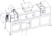
FIG. 1 is a first schematic view of the plastic film wringing machine of the present invention;
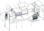
FIG. 2 is a second schematic view of the plastic film wringing machine of the present invention;
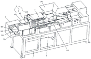
FIG. 3 is a third schematic view of the plastic film wringing machine of the present invention;
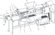
fig. 4 is a fourth schematic view of the plastic film wringing machine of the present invention.
In the figure: 1. a frame body; 2. a drive device; 3. a water squeezing bin; 301. a feed inlet; 302. a water squeezing shaft; 4. compacting the bin; 401. pressing a bin upwards; 402. pressing the bin downwards; 403. a hydraulic cylinder; 5. scattering the materials; 501. a motor; 502. rotating the knife roll; 503. a blade; 504. a discharge port; 6. a drainage bin.
It should be noted that the drawings and the description are not intended to limit the scope of the inventive concept in any way, but to illustrate the inventive concept by those skilled in the art with reference to specific embodiments.
Detailed Description
To make the objects, technical solutions and advantages of the embodiments of the present invention clearer, the drawings in the embodiments of the present invention are combined below to clearly and completely describe the technical solutions in the embodiments, and the following embodiments are used for illustrating the present invention, but do not limit the scope of the present invention.
In the description of the present invention, it should be noted that the terms "upper", "lower", "front", "rear", "left", "right", "vertical", "inner", "outer", and the like indicate orientations or positional relationships based on the orientations or positional relationships shown in the drawings, and are only for convenience of description and simplification of description, but do not indicate or imply that the device or element referred to must have a specific orientation, be constructed and operated in a specific orientation, and thus, should not be construed as limiting the present invention.
In the description of the present invention, it is to be noted that, unless otherwise explicitly specified or limited, the terms "mounted," "connected," and "connected" are to be construed broadly, and may be, for example, fixedly connected, detachably connected, or integrally connected; can be mechanically or electrically connected; may be directly connected or indirectly connected through an intermediate. The specific meaning of the above terms in the present invention can be understood in specific cases to those skilled in the art.
In one embodiment, as shown in fig. 1 to 4, the plastic film wringing machine of the present invention comprises a frame body 1; the upper part of the frame body 1 is sequentially provided with a driving device 2, a water squeezing bin 3, a compacting bin 4 and a scattering bin 5; a drainage bin 6 is arranged at the lower part of the frame body 1 corresponding to the water squeezing bin 3; the top of the water squeezing bin 3 is provided with a feed inlet 301 which is arranged as the film inlet; a water squeezing shaft 302 which is connected with the driving device 2 and is used for sending the film into the compaction bin 4 is arranged in the water squeezing bin 3; the compaction bin 4 extrudes water in the film to the drainage bin 6 under the action of the water extrusion shaft 302, and compacts the film; the compacted film enters the scattering bin 5, and the scattering bin 5 scatters the compacted film.
Particularly, will drive arrangement 2 set up in the lower part of support body 1 for the holistic volume of wringing machine obtains reducing, convenient operation reduces area, and as shown in fig. 1 to fig. 4 the outside of support body 1 sets up the apron that can the switching, can observe after the apron is opened the condition inside the wringing storehouse 3, simultaneously drive arrangement 2 passes through the transmission such as speed reducer, belt, realizes right wringing axle 302 pivoted power transmission reduces the noise, reduces transmission failure, sets up at the front end in compaction storehouse 4 simultaneously and breaks up storehouse 5, after will the compaction the film is broken up, can reduce the human cost, also increases the factor of safety of operation, mainly uses in rubbish recovery field, commodity circulation packing base, film manufacturing industry, seafood market and foam processing enterprise.
Wherein, feed inlet 301 is for leaking hopper-shaped setting, and is close to drive arrangement 2 one side, be convenient for with the film is concentrated fast extremely crowded sump 3.
Further, a helical blade is arranged on the water squeezing shaft 302;
the film is pushed to the compaction bin 4 from the water squeezing bin 3 by the blades, the film is pushed to the compaction bin 4 under the action of the spiral blades, the film is continuously pushed, then the film firstly enters the water squeezing bin 3 and the compaction bin 4 and is extruded by the film entering subsequently, and the moisture in the film entering firstly is extruded to the drainage bin 6 from the water squeezing bin 3.
Furthermore, water leakage holes are uniformly distributed in the water squeezing bin 3;
the drainage bin 6 is arranged at the lower part of the water squeezing bin 3 and used for collecting water discharged by the water leakage holes, and the water leakage holes are at least uniformly distributed at the lower part of the water squeezing bin 3 to form a channel for communicating water squeezed out by the film.
Further, the compacting chamber 4 includes an upper compacting chamber 401 and a lower compacting chamber 402;
the upper pressing bin 401 is a movable bin, and the lower pressing bin 402 is a fixed bin;
the upper pressing bin 401 and the lower pressing bin 402 are buckled with each other to form a cavity for compacting the film, specifically, the extrusion forming of the film is realized through the matching of the upper pressing bin 401 and the lower pressing bin 402, the upper pressing bin 401 is a movable bin and can move in the vertical direction, the lower pressing bin 402 is a fixed bin, the adjustment of the accommodating space of the compacting bin 4 is realized through the movement matching of the upper pressing bin 401 and the lower pressing bin 402, and when the upper pressing bin 401 moves upwards, the film in the compacting bin 4 can also enter the scattering bin 5.
Further, the upper pressing bin 401 and the lower pressing bin 402 are buckled to form a conical opening with a gradually reduced compacting cross section from the feeding end to the discharging end, so that the thin film entering the pressing bin can be squeezed to remove water conveniently.
Further, a hydraulic cylinder 403 is arranged outside the upper pressing bin 401;
the upper pressing bin 401 is connected with the hydraulic cylinder 403 through a piston rod, and the movement of the upper pressing bin 401 is realized through the hydraulic cylinder 403 to provide power for the upper pressing bin 401.
Further, the hydraulic cylinder 403 is provided with a rated pressure value for controlling the opening of the upper pressing chamber 401;
the rated pressure value is equal to the maximum output force of the water squeezing shaft 302, when the film in the compaction bin 4 is too much, the film cannot be pushed forwards, the current of the driving device 2 rises, the upper compaction bin 401 moves upwards under the action of the hydraulic cylinder 403, the compaction bin 4 is opened, and the next process is started.
Specifically, a plc control module connected to the hydraulic cylinder 403 is provided in the control system, the storage amount of the film in the compacting bin 4 is determined by the magnitude of the output force of the driving device 2 driving the squeezing shaft 302, when the current output by the driving device 2 reaches a preset value, the plc control module sends a signal to the hydraulic cylinder 403, the hydraulic cylinder 403 lifts the upper compacting bin 401, the upper compacting bin 401 moves upward, the compacted film enters the loosening bin 5 to be loosened, and the loosened film enters the next process through the discharge port 504.
At the same time, the scattering chamber 5 has
A motor 501 arranged outside the scattering bin 5;
a rotary knife roller 502 arranged inside the scattering bin 5 and connected with the motor 501;
the blade 503 is arranged on the rotary knife roller 502, specifically, the compacted film enters the scattering bin 5, the motor 501 drives the rotary knife roller to rotate, the blade 503 scatters the compacted film, and the scattered film enters the next process.
Further, a discharge port 504 is arranged at the bottom of the scattering bin 5, the scattered film enters the next process from the discharge port 504, meanwhile, the current of the driving device 2 is reduced, the hydraulic cylinder 403 controls the upper pressing bin 401 to move downwards and be buckled with the lower pressing bin 402, the film enters the squeezing bin 3 from the feed port 301, and the squeezing shaft 302 pushes the film to move towards the compacting bin 4, so that the next cycle is realized.
In the description provided herein, numerous specific details are set forth. It is understood, however, that embodiments of the invention may be practiced without these specific details. In some instances, well-known methods, structures and techniques have not been shown in detail in order not to obscure an understanding of this description.
Furthermore, those skilled in the art will appreciate that although some embodiments described herein include some features included in other embodiments instead of others, combinations of features of different embodiments are also meant to be within the scope of the invention and form different embodiments. For example, in the above embodiments, those skilled in the art can use the combination according to the known technical solutions and technical problems to be solved by the present application.
The above description is only a preferred embodiment of the present invention, and is not intended to limit the present invention in any way, and although the present invention has been disclosed with reference to the above preferred embodiment, but not to limit the present invention, any person skilled in the art can make modifications or changes to equivalent embodiments by utilizing the above technical contents without departing from the scope of the present invention, and any simple modification, equivalent change and modification made to the above embodiments by the technical matters of the present invention are within the scope of the present invention.
Claims (10)
1. A plastic film wringing machine is characterized in that: comprises that
A frame body (1);
the upper part of the frame body (1) is sequentially provided with a driving device (2), a water squeezing bin (3), a compacting bin (4) and a scattering bin (5);
a drainage bin (6) is arranged at the lower part of the frame body (1) corresponding to the water squeezing bin (3);
the top of the water squeezing bin (3) is provided with a feed inlet (301) which is arranged as the film inlet;
a water squeezing shaft (302) which is connected with the driving device (2) and is used for sending the film into the compaction bin (4) is arranged in the water squeezing bin (3);
the compaction bin (4) is used for extruding water in the film to the drainage bin (6) under the action of the water extruding shaft (302) and compacting the film;
the compacted film enters the scattering bin (5), and the scattering bin (5) scatters the compacted film.
2. The plastic film wringing machine of claim 1, wherein: the feed inlet (301) is arranged in a funnel shape and is close to one side of the driving device (2).
3. The plastic film wringing machine of claim 2, wherein:
a helical blade is arranged on the water squeezing shaft (302);
the blade pushes the film from the wringing bin (3) to the compacting bin (4).
4. The plastic film wringing machine of claim 3, wherein:
water leakage holes are uniformly distributed in the water squeezing bin (3);
the drainage bin (6) is arranged at the lower part of the water squeezing bin (3) and is used for collecting water drained by the water leakage holes.
5. The plastic film wringing machine of claim 1, wherein:
the compaction bin (4) comprises an upper compaction bin (401) and a lower compaction bin (402);
the upper pressing bin (401) is a movable bin, and the lower pressing bin (402) is a fixed bin;
the upper pressing bin (401) and the lower pressing bin (402) are buckled with each other to form a cavity for compacting the film.
6. The plastic film wringing machine of claim 5, wherein: the upper pressing bin (401) and the lower pressing bin (402) are buckled to form a conical opening with a gradually reduced compacting cross section from the feeding end to the discharging end.
7. The plastic film wringing machine of claim 6, wherein:
a hydraulic cylinder (403) is arranged outside the upper pressing bin (401);
the upper pressing bin (401) is connected with the hydraulic cylinder (403) through a piston rod.
8. The plastic film wringing machine of claim 7, wherein:
the hydraulic cylinder (403) is provided with a rated pressure value for controlling the opening of the upper pressure cabin (401);
the rated pressure value is equal to the maximum output force of the water squeezing shaft (302).
9. The plastic film wringing machine of claim 1, wherein: the scattering bin (5) is provided with a motor (501) and is arranged outside the scattering bin (5);
the rotating knife roller (502) is arranged inside the scattering bin (5) and is connected with the motor (501);
and a blade (503) provided on the rotary knife roller (502).
10. The plastic film wringing machine of claim 9, wherein: and a discharge hole (504) is formed in the bottom of the scattering bin (5).
Priority Applications (1)
| Application Number | Priority Date | Filing Date | Title |
|---|---|---|---|
| CN202020200416.9U CN211808016U (en) | 2020-02-24 | 2020-02-24 | Plastic film wringing machine |
Applications Claiming Priority (1)
| Application Number | Priority Date | Filing Date | Title |
|---|---|---|---|
| CN202020200416.9U CN211808016U (en) | 2020-02-24 | 2020-02-24 | Plastic film wringing machine |
Publications (1)
| Publication Number | Publication Date |
|---|---|
| CN211808016U true CN211808016U (en) | 2020-10-30 |
Family
ID=72999561
Family Applications (1)
| Application Number | Title | Priority Date | Filing Date |
|---|---|---|---|
| CN202020200416.9U Active CN211808016U (en) | 2020-02-24 | 2020-02-24 | Plastic film wringing machine |
Country Status (1)
| Country | Link |
|---|---|
| CN (1) | CN211808016U (en) |
Cited By (2)
| Publication number | Priority date | Publication date | Assignee | Title |
|---|---|---|---|---|
| CN113441228A (en) * | 2021-08-13 | 2021-09-28 | 赖青云 | Waste mulching film recycling and pretreating system |
| CN114505979A (en) * | 2022-01-24 | 2022-05-17 | 郭懒懒 | Compaction equipment in plastic film washs recovery production line |
-
2020
- 2020-02-24 CN CN202020200416.9U patent/CN211808016U/en active Active
Cited By (2)
| Publication number | Priority date | Publication date | Assignee | Title |
|---|---|---|---|---|
| CN113441228A (en) * | 2021-08-13 | 2021-09-28 | 赖青云 | Waste mulching film recycling and pretreating system |
| CN114505979A (en) * | 2022-01-24 | 2022-05-17 | 郭懒懒 | Compaction equipment in plastic film washs recovery production line |
Similar Documents
| Publication | Publication Date | Title |
|---|---|---|
| CN110202816B (en) | Environment-friendly solid-liquid separation device | |
| CN211808016U (en) | Plastic film wringing machine | |
| CN211070238U (en) | Solid waste packing processing apparatus | |
| CN210500972U (en) | Plastic refuse who conveniently screens is retrieved with broken production device that washs again | |
| CN113510963B (en) | Solid-liquid separation device for recycling biological treatment of kitchen waste | |
| CN113510141A (en) | Kitchen garbage utilization biological treatment system | |
| CN114405152A (en) | Mechanical dehydration environmental protection equipment of mud | |
| CN112809987A (en) | Environment-friendly waste plastic bag treatment device and use method thereof | |
| CN216324131U (en) | Domestic garbage treatment device | |
| CN114568721A (en) | Feeding environment-friendly treatment device and treatment method for kitchen waste | |
| CN113509973B (en) | Kitchen waste on-site treatment device | |
| CN214813532U (en) | Antiwind kitchen garbage smashes extrusion device | |
| CN212288868U (en) | Automatic horizontal juicing and dewatering machine of unloading | |
| CN113059840A (en) | Energy-concerving and environment-protective abandonment cardboard compression equipment of using | |
| CN111872057A (en) | Dry-wet separation assembly for kitchen waste | |
| CN110186053B (en) | Environment-friendly solid waste treatment device | |
| CN212882806U (en) | Paper shredder for producing paper boxes | |
| CN114505979A (en) | Compaction equipment in plastic film washs recovery production line | |
| CN213440603U (en) | Crushing and recycling device for waste pipes | |
| CN213107298U (en) | Waste recovery device for cutting bamboo and wood products | |
| CN213035354U (en) | Fruit and vegetable kitchen garbage extruder | |
| CN111841445A (en) | Garbage granulation system and kitchen waste treatment equipment with same | |
| CN113857205A (en) | Kitchen waste recycling processor | |
| CN112944817A (en) | Automatic hydraulic garbage dehydrator | |
| CN218595151U (en) | Intelligent classification box for efficiently recycling garbage |
Legal Events
| Date | Code | Title | Description |
|---|---|---|---|
| GR01 | Patent grant | ||
| GR01 | Patent grant |