CN211582839U - Auxiliary bathing device - Google Patents
Auxiliary bathing device Download PDFInfo
- Publication number
- CN211582839U CN211582839U CN201922309641.6U CN201922309641U CN211582839U CN 211582839 U CN211582839 U CN 211582839U CN 201922309641 U CN201922309641 U CN 201922309641U CN 211582839 U CN211582839 U CN 211582839U
- Authority
- CN
- China
- Prior art keywords
- seat
- scratching
- motor
- rod
- rubbing
- Prior art date
- Legal status (The legal status is an assumption and is not a legal conclusion. Google has not performed a legal analysis and makes no representation as to the accuracy of the status listed.)
- Expired - Fee Related
Links
Images







Landscapes
- Massaging Devices (AREA)
- Devices For Medical Bathing And Washing (AREA)
Abstract
An auxiliary bathing device relates to a bathing device, wherein a seat of a main body of the device is connected with the ground and is arranged at a wall corner, and a common handheld shower nozzle for bathing is arranged on the wall; the automatic leg rubbing mechanism is arranged at the cross beam between the chair legs, comprises two groups of reciprocating motion mechanisms and is symmetrically distributed at the left side and the right side; each mechanism is provided with an independent motor as a power source and passes through a group of cam mechanisms; two groups of motors are arranged below the seat board of the main body seat and connected with a buttock cleaning cloth belt; an electric push rod is arranged below the seat and is connected with the seat plate of the movable seat to lift; the automatic back rubbing mechanism is fixed on the longitudinal beam and is driven by the motor; a height adjusting mechanism is connected to a seat back frame of the main body seat. The utility model discloses supplementary old man or the inconvenient people of health have a bath, combine the massage two kinds of functions of bathing, can relax scalp, back when having a bath, this equipment can reduce the smooth possibility of falling of people by a wide margin simultaneously to the auxiliary person stands, saves physical power more.
Description
Technical Field
The utility model relates to a bathing device, in particular to an auxiliary bathing device.
Background
Under the continuous development of the times, the nation is about to face the aging problem of the population, along with the development trend of aging, a plurality of problems about the old people appear, and the middle-aged and old people have practical problems for bathing. With the increasing age, the physiological functions and physical coordination of the elderly tend to weaken, and the daily life of bathing becomes difficult for the elderly. In this big group of old person, a very big part old person also has the autonomic behavior ability, for convenient these old people oneself take care of oneself, also take care of the feeling of the heart of old person simultaneously, therefore design this a section old person's bathing auxiliary assembly, reduced the physical fitness consumption of old person when bathing, increased the security when the old person bathes simultaneously, let the old person can oneself bathe under safe convenient environment.
Disclosure of Invention
An object of the utility model is to provide an auxiliary bathing device, the utility model discloses equipment realizes assisting old man or the inconvenient people of health to bathe through multi-rod mechanism and biomimetic structure, combines the massage to bathe two kinds of functions, can relax scalp, back when bathing, and this equipment can reduce the smooth possibility of people simultaneously by a wide margin to the auxiliary person stands, saves physical power more.
The utility model aims at realizing through the following technical scheme:
an auxiliary bathing device comprises a main body seat, an automatic back rubbing device, a hip cleaning mechanism, a bionic hair washing and massaging mechanism, an automatic leg rubbing mechanism, a bionic hair washing and massaging swing mechanism, a height adjusting mechanism, a bath rubbing device and a control system; the main body seat is connected with the ground and arranged at the corner of a wall, and a common handheld shower nozzle for bathing is arranged on the wall; the automatic leg rubbing mechanism is arranged at the cross beam between the chair legs, comprises two groups of reciprocating motion mechanisms and is symmetrically distributed at the left side and the right side; each mechanism is provided with an independent motor as a power source and passes through a group of cam mechanisms; two groups of motors are arranged below the seat board of the main body seat and connected with a buttock cleaning cloth belt; an electric push rod is arranged below the seat and is connected with the seat plate of the movable seat to lift; the automatic back rubbing mechanism is fixed on the longitudinal beam and is driven by the motor; a seat back frame of the main body seat is connected with a height adjusting mechanism; the height adjusting mechanism is provided with a manual adjusting bionic hair washing massage mechanism; a bionic hair washing massage swinging mechanism is arranged above the height adjusting mechanism and is connected with the bionic hair washing massage swinging mechanism through a swing rod mechanism by a motor; the bionic hair washing and massaging mechanism consists of three groups of same gripper mechanisms, and each group of the gripper mechanisms is connected by motor power.
The main body seat comprises pedals, a seat chair leg frame, armrests, a seat backrest frame, a seat fixing frame, a seat board, angle steel bars and a cross beam between the seat chair legs; the chair leg frame and the cross beam between the chair legs are fixedly connected through screws, and the chair leg frame is connected to the chair fixing frame through bolts.
In the auxiliary bathing device, the automatic back rubbing device is provided with a reciprocating mechanism, and a limit block in the reciprocating mechanism is fixed on a connecting plate; the polish rod II is arranged in the groove of the limiting block and is in relative sliding connection with the limiting block; the reciprocating mechanism passes through a connecting rod And the cam seat is connected with the cam seat in a swinging way.
In the auxiliary bathing device, the driving cleaning belt wheel of the hip cleaning mechanism is sleeved on the transmission shaft and is connected with the transmission shaft through a key; the transmission shaft is fixedly arranged on the fixed plate through a bearing; the driven cleaning belt wheel is sleeved on the polish rod III, and a bearing is arranged between the driven cleaning belt wheel and the polish rod III; the cleaning cloth belts are arranged on the four belt wheels; the adjacent belt wheels are separated by fixing plates, and the adjacent fixing plates are fixed by pull rods; the secondary synchronous pulley is arranged on the transmission shaft through a jackscrew.
The bionic hair washing and massaging mechanism comprises three groups, wherein each group comprises a scratching head shell, a scratching head, a scratching outer sleeve, a connecting buckle, a connecting rod III, an eccentric wheel and a motor base Motor
Motor A flexible grabbing inner rod and a connecting rod IV; the scratching inner rod is sleeved in the scratching outer sleeve, and the scratching head, the scratching outer sleeve, the scratching inner rod and the connecting rod IV are connected through a pin shaft;
 flex grip housing 34 is secured within the flex head housing.
In the auxiliary bathing device, the automatic leg rubbing mechanism is provided with a reciprocating mechanism; the connecting plate in the automatic leg rubbing mechanism is fixed on a cross beam between chair stool legs through bolts, the leg rubbing plate is fixed on a connecting frame in the automatic leg rubbing mechanism through screws, and the back plate is provided with a back rubbing self-adaptive block.
The bionic hair washing and massaging swing machine comprises three groups, wherein each group comprises a scratching head shell, a grabbing head, a scratching outer sleeve, a connecting buckle, a connecting rod III, an eccentric wheel and a motor base Motor
Motor A flexible grabbing inner rod and a connecting rod IV; the scratching inner rod is sleeved in the scratching outer sleeve, and the scratching head, the scratching outer sleeve, the scratching inner rod and the connecting rod IV are connected through a pin shaft; the scratching outer sleeve is fixed in the scratching head shell; connection ofThe buckle is connected with the scratching inner rod through a screw.
In the auxiliary bathing device, the slide block penetrates through the polish rod I of the height adjusting mechanism, and the polish rod frames fixed at two ends are fixed on the hair washing base through bolts; the buckle shell is connected with the buckle through a pin shaft, and the buckle shell and the connecting seat are installed on the sliding block through screws; the head bending rocker base is fixed on the hair washing base through a bolt, and the head bending shell, the connecting rod I and the connecting rod II are connected through a pin shaft.
The auxiliary bathing device comprises a back shell of the bath rubbing device, a front shell of the bath rubbing device, a rotary table for rubbing the bath, a handle and a motor VI; the motor VI and the front shell of the bath rubbing device are fixed through screws, the bath rubbing rotary disc is fixed on the motor VI through jackscrews, the back shell of the bath rubbing device and the front shell of the bath rubbing device are locked and locked through the buckles, and the handle, the back shell of the bath rubbing device and the front shell of the bath rubbing device are connected with the handle through threads arranged on the back shell of the bath rubbing device and the bath rubbing device.
The control system of the auxiliary bathing device comprises a single chip microcomputer, a button switch and a brushless motor.
The utility model has the advantages and effects that:
the utility model discloses a bionical massage mechanism of washing hair can be for automatic washing hair, the massage of old person and the inconvenient people of health, through buttock wiper mechanism self-cleaning buttock, through rubbing with the hands back mechanism self-cleaning back automatically, reduces bather's physical stamina consumption.
The utility model discloses main part seat is with the supplementary function of standing and helps the people to stand, guarantees the people's of bathing security, and the device function is more can assist the old man of independent life ability or weak people's use.
Drawings
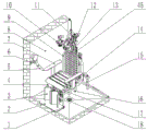
FIG. 1 is a schematic view of the three-dimensional structure of the present invention;
FIG. 2 is an oblique view and bottom detail display of the present invention;
fig. 3 is a schematic view of the main body seat state when the utility model assists the elderly to stand up;
FIG. 4 is a schematic view of the hair washing and massaging device of the present invention;
FIG. 5 is a side view of the hair washing massage paw of the present invention;
FIG. 6 is a cross-sectional view of the self-adaptive hair washing massage claw of the present invention;
FIG. 7 is a cross-sectional view of the gripper head of the adaptive hair washing massage gripper of the present invention;
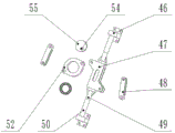
fig. 8 is a schematic view of the automatic leg-rubbing mechanism and the automatic back-rubbing mechanism (the reciprocating mechanism) of the present invention;
fig. 9 is a back oblique view of the automatic leg-rubbing mechanism and the automatic back-rubbing mechanism (the reciprocating mechanism involved) of the present invention;
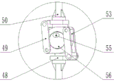
fig. 10 is a sectional view of the cam structure of the automatic leg-rubbing mechanism and the automatic back-rubbing mechanism (the reciprocating mechanism concerned) of the present invention;
FIG. 11 is a schematic view of the hip scrubbing device of the present invention;
FIG. 12 is a view showing the inner structure of the hip washing device of the present invention;
fig. 13 is a sectional view of the self-adaptive structure of the back plate of the utility model for adapting to the back curve of the old;
FIG. 14 is a schematic view of an auxiliary bath device of the present invention;
FIG. 15 is a schematic view of the internal structure of the auxiliary bath device of the present invention;
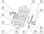
FIG. 16 is an exploded view of the hip cleaning mechanism of the present invention;
FIG. 17 is an exploded view of the reciprocating mechanism of the automatic back rubbing mechanism and the automatic leg rubbing mechanism of the present invention;
fig. 18 is a schematic view of the automatic leg-rubbing mechanism and the automatic back-rubbing mechanism (the reciprocating mechanism involved) of the present invention;
FIG. 19 is a view showing the actual installation of the automatic leg rubbing mechanism of the present invention;
fig. 20 is an actual installation view of the automatic back rubbing structure of the present invention.
Fig. 21 is a connection diagram of the control system of the present invention.
The components in the figure: 1- 'L' -shaped corner piece, 2-pedal, 3-leg rubbing board, 4-chair leg frame, 5-bath device,6-bath scrubber frame, 7-handrail, 8-baffle, 9-seat back frame, 10-bending head shell, 11-bending head rocker base, 12-buckle shell, 13-hair washing base, 14-horizontal beam, 15-bearing frame, 16-seat fixing frame, 17-seat plate, 18-water outlet, 19-angle steel bar, 20-beam between seat legs, 21-back plate, 22-fixing seat, 23-electric push rod fixing frame and 24-electric push rod 25-gripper head, 26-spray head and 27-connecting rod
 28-connecting rod
 29-electric machine
 30-motor base
 31-fastener, 32-polished rod frame and 33-polished rod
 34-scratching coat, 35-connecting buckle and 36-connecting rod III
 37-eccentric wheel, 38-motor base
 39-motor
 40-connecting seat
 41-sliding block, 42-scratching inner rod, 43-connecting rod IV, 44-back rubbing self-adapting block, 45-longitudinal beam, 46-connecting frame, 47-limiting block, 48-limiting shell and 49-connecting rod
 50-connecting seat
 51-polished rod
 52-connecting plate, 53-cam seat and 54-
motor
55 cam shaft, 56 cam, 57 connecting seat, 58 fixing plate, 59 cleaning cloth belt, 60 motor seat, 61 transmission shaft, 62 synchronous belt, 63 driven synchronous pulley, 64 primary synchronous pulley and 65 motor 66-driven cleaning pulley, 67-polished rod
 68-pull rod, 69-driving cleaning belt wheel, 70-back shell of bath scrubber, 71-front shell of bath scrubber, 72-rotary table of bath scrubber, 73-handle and 74-motor
 。
。
Detailed Description
The present invention will be described in detail with reference to the embodiments shown in the drawings.
As shown in fig. 1, the main body seat is placed on the ground. The main body seat comprises a pedal 2, a seat leg frame 4, an armrest 7, a seat back frame 9, a seat fixing frame 16, a seat board 17, an angle steel bar 19 and a cross beam 20 between seat legs. The seat leg frame 4 and the cross member 20 between the seat legs are fixedly connected by screws, and the seat leg frame 4 is connected to the seat holder 16 by bolts, while the armrest 7 is mounted on the seat holder 16 and fixed by bolts. The angle steel bar 19 is bolted to the seat leg frame 4 as shown in fig. 1, and the step 2 is bolted to the seat leg frame 4 using the "L" shaped corner fitting 1. As shown in fig. 1, the seat back frame 9 and the seat leg frame 4 are fixed by bolts. The seat back frame 9 and the longitudinal member 45 are fixed by bolts. The seat holder 16 is fixed to the horizontal cross member 14 by bolts, so that the seat holder 16 in the main body seat is connected to the horizontal cross member 14 behind the seat holder. The horizontal beam is fixed on the bearing frame 15 through bolts and is connected and fixed with the ground through bolts. The user can install the baffle 8 according to the installation position use habit and the like, and can not install the baffle 8 additionally.
The automatic back rubbing mechanism comprises a back plate 21, a back rubbing self-adaptive block 44, a connecting frame 46, a limiting block 47, a limiting shell 48 and a connecting rod
49. The connecting seat, polished rod II51, connecting plate 52, cam seat 53, motor IV54, camshaft 55, cam 56. Automatic leg rubbing mechanism includes: leg rubbing plate 3, connecting frame 46, limiting block 47, limiting shell 48 and connecting rod
49. Connecting seat
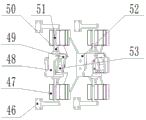
50. Polished rod II51, connecting plate 52, cam seat 53, motor IV54, camshaft 55, cam 56. The automatic back rubbing mechanism and the automatic leg rubbing mechanism both relate to a set of reciprocating mechanism with the same principle, and the reciprocating mechanism only relates to different motor powers and different sizes of connecting pieces. The diagram of the reciprocating mechanism concerned is shown in the figure, the stopper 47 being fixed to the connecting plate 52. The polished rod II51 is arranged in the groove of the limiting block and can slide relative to the limiting block 47. The reciprocating mechanism can be connected with the connecting rod
49 and the cam seat 53 swing to decompose the cam rotation into vertical polish rod II5 axis motion and motion along polish rod II51 axis motion, and play a guiding role along polish rod II51 axis direction. Under the limitation of the limiting block 47, the connecting frame 46, the limiting shell 48, the connecting seat II 60 and the polish rod II can only move along the central axis of the polish rod II51 to realize reciprocating motion. Automatic back rubbing mechanism and automatic back rubbing machineThe reciprocating mechanism related to the leg rubbing mechanism consists of a connecting frame 46, a limiting block 47, a limiting shell 48 and a connecting rod
49. Connecting seat
50. Polished rod II51, connecting plate 52, cam seat 53, motor IV54, camshaft 55, cam 56 make up, as shown in fig. 10, camshaft 55 is fixed into cam 56, and the bearing inner ring is inlayed to cam 56 one side, and the bearing outer ring is inlayed cam seat 53. Connecting seat
50 is fixed on the limit shell 48 through a screw, and the polish rod II51 is fixed on the connecting seat
50, a limit shell 48 and a connecting rod are arranged 49 and
 cam seat 53 are connected by a pin. As shown in fig. 8, the limiting block 47 is sleeved on the polish rod II51, and the other end of the polish rod II51 is fixed with the connecting frame 46. The stopper 47 is fixed to the connecting plate 52 by bolts. The motor IV54 is fixed to the connecting plate 52 by screws and is connected to the cam shaft 55 by a coupling. As shown in fig. 20, in the automatic back rubbing mechanism, a connecting plate 52 in the automatic back rubbing mechanism is fixed on a longitudinal beam 45 through a bolt, and a back plate 21 is fixed on a connecting frame 46 in the automatic back rubbing mechanism through a screw.
In the automatic leg-scrubbing mechanism, the connecting plate 52 of the automatic leg-scrubbing mechanism is fixed to the cross member 20 between the seat legs by bolts, and the leg-scrubbing plate 3 is fixed to the connecting frame 46 of the automatic leg-scrubbing mechanism by screws, as shown in fig. 19. In order to adapt to the user during back rubbing, a back rubbing adaptive block 44 is arranged on the back plate 21, as shown in fig. 13, and is installed in a buckling and clamping manner, and meanwhile, a spring with moderate elasticity is arranged between the back plate and the back plate, so that the back rubbing adaptive block is automatically adapted to the shape of the back of the old. The back rubbing mechanism has two back plates 21, and each back plate 21 is provided with 4 multiplied by 10 back rubbing self-adaptive blocks 44.
The hip cleaning mechanism comprises a connecting seat 57, a fixing plate 58, a cleaning cloth belt 59, a motor seat 60, a transmission shaft 61, a synchronous belt 62, a secondary synchronous pulley 63, a primary synchronous pulley 64, a motor V65, a secondary cleaning pulley 66, a polished rod III67, a pull rod 68 and a driving cleaning pulley 69. The driving cleaning pulley 69 is sleeved on the transmission shaft 61 and is connected with the transmission shaft 61 through a key. The transmission shaft 61 is fixedly mounted on the fixing plate 58 through a bearing. The driven cleaning pulley 66 is sleeved on the polish rod III67 and a bearing is arranged between the driven cleaning pulley and the polish rod III 67. The cleaning cloth belts 59 are mounted on four pulleys. Adjacent pulleys are separated by a retaining plate 58 and adjacent 2 retaining plates are retained by tie rods 68. The driven timing pulley 63 is attached to the transmission shaft 61 via a jack screw. The motor V65 is installed on the motor base 60, and the motor base 60 is fixed on the fixing plate 58 through screws. The primary timing pulley 64 is fixed to a motor V65 via a jack screw, and the primary timing pulley 64 and the secondary timing pulley 63 are connected via a timing belt 62. The connecting seat 57 is fixed on the fixing plate 58 through screws, the connecting seat 57 is connected below the seat plate 17 through screws, and the seat plate 21 plays a main role in bearing and supporting during operation. The motor of the hip cleaning mechanism is installed in central symmetry when overlooking. The total four clean strap of buttock wiper mechanism, wherein 1 st, 3 rd clean strap can rotate in step. The cleaning cloth belt is driven by a motor, wherein the 2 nd and 4 th cleaning cloth belts synchronously rotate, can be opposite to the rotation direction of the 1 st and 3 rd cleaning cloth belts and is driven by another motor. Two transmission shafts are respectively arranged at the driving cleaning belt wheel of the 1 st and the 3 rd cleaning cloth belts and the 2 nd cleaning cloth belt, and the driving cleaning belt wheel of the 4 th cleaning cloth belt is provided with a key groove. The bearing is arranged in the inner diameter of the driven cleaning belt wheel, and the inner diameter of the bearing is sleeved on the polish rod or the transmission shaft.
The mechanism involved in elderly getting up includes: fixing seat 22, electric push rod fixing frame 23 and electric push rod
24. As shown in fig. 2, the fixing base 22 is fixed on the horizontal beam 14 by a section bar screw, the electric push rod fixing frame 23 is installed on the fixing base 22 by a bolt, the end of the electric push rod I24 motor is connected with the electric push rod fixing frame 23 by a pin shaft, and the electric push rod is pushed by electricityThe telescopic end of the rod I24 is connected with the seat plate 17 through a pin shaft.
The bionic hair washing massage mechanism comprises three groups, wherein each group comprises: scratching head shell 10, grabbing head 25, scratching outer sleeve 34, connecting buckle 35, connecting rod III36, eccentric wheel 37 and motor base
38. Electric machine
39. The inner rod 42 and the connecting rod IV43 are scratched. The scratching inner rod 42 is sleeved in the scratching outer sleeve 34, and the scratching head 25, the scratching outer sleeve 34, the scratching inner rod 42 and the connecting rod IV43 are connected through a pin shaft. A flex-grip sheath 34 is secured within flex-head housing 10. The connecting buckle 35 is connected with the inner flexible grasping rod 42 through a screw. The motor base is installed on the flexible head shell 10 through the screw, motor II39 is fixed on motor base II38, eccentric wheel 37 is fixed on motor II39 through the jackscrew, connecting rod III36 is fixed on eccentric wheel 37 through the screw, and connecting rod III36 and connector link 35 are connected through the round pin axle. Three bionic hair washing massage mechanisms are arranged on the hair scratching shell 10, included angles among the three bionic hair washing massage mechanisms are all 120 degrees, and each bionic hair washing massage mechanism is provided with five grabbers. Each group is grabbed with a single motor for power supply. The gripper head 25 is divided into two parts as shown in fig. 7, the part B is clipped on the part A through a buckle
The height adjustment mechanism includes: the flexible head rocker base 11, the buckle shell 12, the hair washing base 13, the connecting rod I27, the connecting rod II28, the motor I29, the motor base I30, the buckle 31, the polished rod frame 32, the polished rod I33, the connecting seat 40 and the sliding block 41. The slide block 41 is penetrated on the polish rod I33, and the polish rod frame 32 fixed at two ends is fixed on the hair washing base 13 through bolts. The snap housing 12 and the snap 31 are connected by a pin, and the snap housing 12 and the connecting holder 40 are mounted on the slider 41 by a screw. The scratching head rocker base 11 is fixed on the hair washing base 13 through bolts, and the scratching head shell 10, the connecting rod I27 and the connecting rod II28 are connected through a pin shaft. The motor cabinet I30 is fixed on the flexible head rocker base 11 through bolts, the motor I29 is installed on the motor cabinet I30, and the motor I29 is connected with the connecting rod II28 through a coupler. The self-adaptive hair washing massage device is installed through the hair washing base 13 and the longitudinal beam 45 in a bolt connection mode.
The bath device comprises a bath device rear shell 70, a bath device front shell 71, a bath rotary disc 72, a handle 73 and a motor VI 74. The motor VI74 and the front shell 71 of the bath device are fixed through screws, the rotary bathing disc 72 is fixed on the motor VI74 through jackscrews, the back shell 70 of the bath device and the front shell 71 of the bath device are locked through buckles, and the handle 73, the back shell 70 of the bath device and the front shell 71 of the bath device are connected with the handle 73 through threads arranged on the back shell 70 of the bath device and the front shell 71 of the bath device.
The bath rubbing device frame 6 is fixed on the wall surface or the baffle 8 through screws, and the bath rubbing device is clamped in the bath rubbing device frame.
The control system is controlled by a single chip microcomputer, a button switch is manually pressed to transmit a signal to the single chip microcomputer system, and the signal is electrically adjusted to the brushless direct current motors through processing to control the brushless direct current motors to work.
The utility model discloses a working method:
when the old people need to operate the machine, the old people only need to sit on the seat. If the machine is used for the first time, the buckle 31 can be loosened to adjust the position of the hair washing massage device through the height adjusting mechanism, the buckle is locked after the proper position is reached, and the height of the hair washing massage device is adjusted in advance. The old person can adjust the temperature and begin the bathing, when the old person need scrub buttock and thigh root, press and scrub the buttock switch, the buttock scrubbing device under bedplate 17 will work, motor V65 drives initiative cleaning belt wheel 69 and then drives clean strap 59 and rotate, one of them motor V65 drives 1 st, 3 rd clean strap is rotatory, another motor V65 drives 2 nd, 4 th clean strap is rotatory, and with 1 st, 3 rd clean strap direction of rotation is opposite. Two adjacent cloth belts are opposite in advancing direction, and the old can finish hip cleaning only by adjusting the sitting position of the old. When the old needs to rub the lower legs and the back, the back rubbing button is pressed, the motor IV54 drives the cam shaft 55 to rotate, and because the connecting seat II50 and the polish rod II51 are both in the limiting block 47, the axis of the cam shaft 55 and the axis of the polish rod II51 are coplanar, the connecting frame 46 is driven to reciprocate, and then the leg rubbing plate and the back plate are driven to reciprocate. When the old needs to wash or massage, the old can press down the hair washing button, the motor I29 drives the connecting rod II28 to rotate, the connecting rod II28, the connecting rod I27 and the head bending shell 10 are four-bar mechanisms, and when the connecting rod II28 rotates, the connecting rod I27 is driven to swing, so that the head bending shell rotates, and the head of the old is guaranteed to be attached; after the scratching head shell 10 is lowered to a proper position, the motor II39 drives the eccentric wheel 37 to rotate, the eccentric wheel 37 drives the connecting rod III36 to further drive the scratching inner rod 42 to reciprocate along the direction of the central axis of the scratching outer sleeve 34, and the scratching head 25 is driven by the connecting rod IV43 through pin shaft connection, so that the scratching operation imitating hand washing of a person is scratched by scratching. The rest parts of the body can be washed by a matched bath device. When the button of the bath rubbing device is pressed down, the bath rubbing rotary disc 72 is driven by the motor VI74 to rotate for bath. After the bathing of old person is ended, press motor I29 behind the end button and drive connecting rod II28 and lift, drive through connecting rod I27 and scratch first shell 10 and lift, vacate the space for the old person rises up, electric putter I24 begins work this moment, through the rotation of electric putter I24 extension bedplate 17 looks front, turned angle is about 50 degrees, the old person can accomplish through the bedplate helping hand and stand, the old person rises up the back electric putter and withdraws, bedplate 17 is rotatory the normal position backward.
Details of the application: the device is externally provided with a pipeline similar to common bathing equipment, each spray head is provided with an adjustable temperature control switch, and the temperature and the water supply are set by the old; the side surface is provided with a handheld spray head; the self-adaptive hair washing massage claw is externally provided with a silica gel jacket so as to improve the comfort level of the self-adaptive hair washing massage claw; the leg rubbing auxiliary device, the self-adaptive auxiliary back rubbing structure and the rubbing disc are sleeved with rubbing cloth; all motors adopt waterproof brushless motors available in the market, such as 4270-; all metal components are subjected to rust prevention treatment (such as nickel plating treatment); the bearings are all waterproof bearings which can be bought in the market, such as sealed waterproof bearings of Tianmaqisi hardware special shops; the adopted switches are all rust-proof and waterproof switches which can be bought in the market, such as led annular waterproof small switch buttons with lamps in flag warships with good gym cats.
Claims (10)
1. An auxiliary bathing device is characterized by comprising a main body seat, an automatic back rubbing device, a hip cleaning mechanism, a bionic hair washing and massaging mechanism, an automatic leg rubbing mechanism, a bionic hair washing and massaging swing mechanism, a height adjusting mechanism, a bath rubbing device and a control system; the main body seat is connected with the ground and arranged at the corner of a wall, and a common handheld shower nozzle for bathing is arranged on the wall; the automatic leg rubbing mechanism is arranged at the cross beam between the chair legs, comprises two groups of reciprocating motion mechanisms and is symmetrically distributed at the left side and the right side; each mechanism is provided with an independent motor as a power source and passes through a group of cam mechanisms; two groups of motors are arranged below the seat board of the main body seat and connected with a buttock cleaning cloth belt; an electric push rod is arranged below the seat and is connected with the seat plate of the movable seat to lift; the automatic back rubbing mechanism is fixed on the longitudinal beam and is driven by the motor; a seat back frame of the main body seat is connected with a height adjusting mechanism; the height adjusting mechanism is provided with a manual adjusting bionic hair washing massage mechanism; a bionic hair washing massage swinging mechanism is arranged above the height adjusting mechanism and is connected with the bionic hair washing massage swinging mechanism through a swing rod mechanism by a motor; the bionic hair washing and massaging mechanism consists of three groups of same gripper mechanisms, and each group of the gripper mechanisms is connected by motor power.
2. An auxiliary bathing device according to claim 1, wherein the main body seat comprises a pedal (2), a seat leg frame (4), an armrest (7), a seat back frame (9), a seat fixing frame (16), a seat plate (17), an angle steel bar (19), a seat leg cross beam (20); the chair leg frame (4) and the cross beam (20) between the chair legs are fixedly connected through screws, and the chair leg frame (4) is connected to the chair fixing frame (16) through bolts.
3. An auxiliary bathing device according to claim 1, wherein the automatic back rubbing device is provided with a reciprocating mechanism, and a limit block (47) in the reciprocating mechanism is fixed on the connecting plate (52); the polish rod II (51) is arranged in the groove of the limiting block and is in relative sliding connection with the limiting block (47); the reciprocating mechanism passes through a connecting rod (49) And the cam seat (53) is connected in a swinging way.
4. An auxiliary bathing device according to claim 1 wherein the drive washing pulley (69) of the hip washing mechanism is fitted over the drive shaft (61) and keyed thereto; the transmission shaft (61) is fixedly arranged on the fixing plate (58) through a bearing; the driven cleaning belt wheel (66) is sleeved on the polish rod III (67) and a bearing is arranged between the driven cleaning belt wheel and the polish rod III; the cleaning cloth belts (59) are arranged on the four belt wheels; the adjacent belt wheels are separated by a fixing plate (58) and are fixed by a pull rod (68); the driven synchronous pulley (63) is mounted on the transmission shaft (61) through a jackscrew.
5. An auxiliary bathing device according to claim 1 wherein said bionic hair washing and massaging mechanism comprises three groups, each group comprising a scratching head shell (10), a grabbing head (25), a scratching outer sleeve (34), a connecting buckle (35), a connecting rod III (36), an eccentric wheel (37), and a motor base (38) Motor
 (39) A scratching inner rod (42) and a connecting rod IV (43); the scratching inner rod (42) is sleeved in the scratching outer sleeve (34), and the scratching head (25), the scratching outer sleeve (34), the scratching inner rod (42) and the connecting rod IV (43) are connected through a pin shaft; the scratching outer sleeve (34) is fixed in the scratching head shell (10).
6. An auxiliary bathing device according to claim 1 wherein said automatic leg scrubbing mechanism is provided with a reciprocating mechanism; a connecting plate (52) in the automatic leg rubbing mechanism is fixed on a cross beam (20) between chair stool legs through bolts, a leg rubbing plate (3) is fixed on a connecting frame (46) in the automatic leg rubbing mechanism through screws, and a back rubbing self-adaptive block is arranged on a back plate (21).
7. An auxiliary bathing device according to claim 1 wherein said bionic hair-washing massage oscillating machine comprises three groups, each group comprising a scratching head shell (10), a scratching head (25), and a scratching outer sleeve (3)4) A connecting buckle (35), a connecting rod III (36), an eccentric wheel (37) and a motor base (38) Motor
 (39) A scratching inner rod (42) and a connecting rod IV (43); the scratching inner rod (42) is sleeved in the scratching outer sleeve (34), and the scratching head (25), the scratching outer sleeve (34), the scratching inner rod (42) and the connecting rod IV (43) are connected through a pin shaft; the scratching outer sleeve (34) is fixed in the scratching head shell (10); the connecting buckle (35) is connected with the scratching inner rod (42) through a screw.
8. An auxiliary bathing device according to claim 1, wherein the slide block (41) is penetrated on the polish rod I (33) of the height adjusting mechanism, and the polish rod frames (32) fixed at two ends are fixed on the hair washing base (13) through bolts; the buckle shell (12) is connected with the buckle (31) through a pin shaft, and the buckle shell (12) and the connecting seat (40) are installed on the sliding block (41) through screws; the head bending rocker base (11) is fixed on the hair washing base (13) through a bolt, and the head bending shell (10), the connecting rod I (27) and the connecting rod II (28) are connected through a pin shaft.
9. An auxiliary bathing device according to claim 1 wherein said scrubber component comprises a scrubber rear shell (70), a scrubber front shell (71), a scrubber turntable (72), a handle (73), and a motor VI (74); the motor VI (74) and the front shell (71) of the bath device are fixed through screws, the bath rotating disc (72) is fixed on the motor VI (74) through jackscrews, the rear shell (70) of the bath device and the front shell (71) of the bath device are locked through buckles, and the handle (73), the rear shell (70) of the bath device and the front shell (71) of the bath device are connected with the handle (73) through threads arranged on the rear shell (70) of the bath device and the front shell (71) of the bath device.
10. An auxiliary bathing device according to claim 1 wherein said control system comprises a single chip microcomputer, a push button switch, and a brushless motor.
Priority Applications (1)
| Application Number | Priority Date | Filing Date | Title |
|---|---|---|---|
| CN201922309641.6U CN211582839U (en) | 2019-12-20 | 2019-12-20 | Auxiliary bathing device |
Applications Claiming Priority (1)
| Application Number | Priority Date | Filing Date | Title |
|---|---|---|---|
| CN201922309641.6U CN211582839U (en) | 2019-12-20 | 2019-12-20 | Auxiliary bathing device |
Publications (1)
| Publication Number | Publication Date |
|---|---|
| CN211582839U true CN211582839U (en) | 2020-09-29 |
Family
ID=72594035
Family Applications (1)
| Application Number | Title | Priority Date | Filing Date |
|---|---|---|---|
| CN201922309641.6U Expired - Fee Related CN211582839U (en) | 2019-12-20 | 2019-12-20 | Auxiliary bathing device |
Country Status (1)
| Country | Link |
|---|---|
| CN (1) | CN211582839U (en) |
Cited By (3)
| Publication number | Priority date | Publication date | Assignee | Title |
|---|---|---|---|---|
| CN112656263A (en) * | 2020-11-12 | 2021-04-16 | 杭州电子科技大学 | Auxiliary bathing robot device and working method thereof |
| CN113116195A (en) * | 2021-05-15 | 2021-07-16 | 台州学院 | Old person uses new-type chair of bathing |
| CN115281551A (en) * | 2022-08-30 | 2022-11-04 | 郑州澍青医学高等专科学校 | Back cleaning auxiliary bathing device and using method thereof |
-
2019
- 2019-12-20 CN CN201922309641.6U patent/CN211582839U/en not_active Expired - Fee Related
Cited By (5)
| Publication number | Priority date | Publication date | Assignee | Title |
|---|---|---|---|---|
| CN112656263A (en) * | 2020-11-12 | 2021-04-16 | 杭州电子科技大学 | Auxiliary bathing robot device and working method thereof |
| CN112656263B (en) * | 2020-11-12 | 2022-02-11 | 杭州电子科技大学 | Auxiliary bathing robot device and working method thereof |
| CN113116195A (en) * | 2021-05-15 | 2021-07-16 | 台州学院 | Old person uses new-type chair of bathing |
| CN115281551A (en) * | 2022-08-30 | 2022-11-04 | 郑州澍青医学高等专科学校 | Back cleaning auxiliary bathing device and using method thereof |
| CN115281551B (en) * | 2022-08-30 | 2024-07-26 | 郑州澍青医学高等专科学校 | Back cleaning auxiliary bath device and application method thereof |
Similar Documents
| Publication | Publication Date | Title |
|---|---|---|
| CN211582839U (en) | Auxiliary bathing device | |
| CN202408698U (en) | Multifunctional automatic bathing machine | |
| CN102670125B (en) | Multifunctional automatic bathing machine | |
| CN110215141A (en) | A kind of auxiliary the elderly's shoulder and the chair type washed by rubbing with the hands of back wash integrated bath chair by rubbing with the hands | |
| CN112057313B (en) | Leg massage device for gynecology | |
| CN102670114B (en) | Multifunctional automatic human body scrubbing device | |
| CN110558883B (en) | Bath chair | |
| CN202477512U (en) | Multi-purpose human body automatic bathing device | |
| CN111195092A (en) | Multifunctional bathing chair for old people | |
| CN208405292U (en) | A kind of scrubbing back and massaging device | |
| CN109893009B (en) | Bathing device suitable for hair is clean | |
| CN102670113B (en) | Three-dimensional motion shank rubbing device for bath | |
| CN210989896U (en) | Bathing chair | |
| CN111248793A (en) | Integrated bathing chair for assisting old people in limb stretching and back scrubbing | |
| CN212382551U (en) | Upper and lower body rotary cleaning, rubbing, massaging and liquid spraying device | |
| CN112754339B (en) | Multifunctional bathing device convenient for disabled people to use | |
| CN113197503B (en) | Anti-falling type old people bathing auxiliary device | |
| CN212382931U (en) | Head cleaning and massaging device | |
| CN219422701U (en) | Automatic health-care body cleaner | |
| CN113876224B (en) | Posture-adjustable auxiliary appliance for nursing and bathing for aged people | |
| CN214906259U (en) | Old nursing shower chair | |
| CN212382546U (en) | Bathing seat backrest opening and closing device | |
| CN212465822U (en) | Automatic change old man's bathing assistant and rub massage cream coating device | |
| CN2759454Y (en) | Automatic back rubbing massager for shower | |
| CN213076481U (en) | Walking type massage machine core |
Legal Events
| Date | Code | Title | Description |
|---|---|---|---|
| GR01 | Patent grant | ||
| GR01 | Patent grant | ||
| CF01 | Termination of patent right due to non-payment of annual fee |
Granted publication date: 20200929 Termination date: 20211220 |
|
| CF01 | Termination of patent right due to non-payment of annual fee |