CN211424839U - Refrigerating machine heat abstractor for refrigeration plant - Google Patents
Refrigerating machine heat abstractor for refrigeration plant Download PDFInfo
- Publication number
- CN211424839U CN211424839U CN202020096760.8U CN202020096760U CN211424839U CN 211424839 U CN211424839 U CN 211424839U CN 202020096760 U CN202020096760 U CN 202020096760U CN 211424839 U CN211424839 U CN 211424839U
- Authority
- CN
- China
- Prior art keywords
- refrigerator
- pipe
- water
- main body
- water tank
- Prior art date
- Legal status (The legal status is an assumption and is not a legal conclusion. Google has not performed a legal analysis and makes no representation as to the accuracy of the status listed.)
- Expired - Fee Related
Links
- 238000005057 refrigeration Methods 0.000 title claims description 6
- XLYOFNOQVPJJNP-UHFFFAOYSA-N water Substances O XLYOFNOQVPJJNP-UHFFFAOYSA-N 0.000 claims abstract description 109
- 238000001816 cooling Methods 0.000 claims abstract description 46
- 230000017525 heat dissipation Effects 0.000 claims abstract description 34
- 238000010438 heat treatment Methods 0.000 claims abstract description 27
- 239000004519 grease Substances 0.000 claims abstract description 8
- 229920001296 polysiloxane Polymers 0.000 claims abstract description 8
- 238000007789 sealing Methods 0.000 claims description 3
- 230000000694 effects Effects 0.000 abstract description 9
- 239000000498 cooling water Substances 0.000 abstract description 3
- 238000007689 inspection Methods 0.000 description 7
- 238000010586 diagram Methods 0.000 description 3
- 238000000034 method Methods 0.000 description 3
- 238000012986 modification Methods 0.000 description 2
- 230000004048 modification Effects 0.000 description 2
- 238000012271 agricultural production Methods 0.000 description 1
- 230000009286 beneficial effect Effects 0.000 description 1
- 239000003989 dielectric material Substances 0.000 description 1
- 238000005516 engineering process Methods 0.000 description 1
- 230000020169 heat generation Effects 0.000 description 1
- 239000012535 impurity Substances 0.000 description 1
- 238000009776 industrial production Methods 0.000 description 1
- 238000009413 insulation Methods 0.000 description 1
- 230000007774 longterm Effects 0.000 description 1
- 239000003507 refrigerant Substances 0.000 description 1
Images


Landscapes
- Devices That Are Associated With Refrigeration Equipment (AREA)
Abstract
本实用新型涉及制冷机技术领域,尤其为一种制冷设备用制冷机散热装置,包括制冷机主体、水箱和散热风扇,制冷机主体基面安装有检修门,所述检修门一侧设有门锁,所述检修门底端开设有散热口,所述检修门上方设有凹槽,所述凹槽内设有多组进风口,所述进风口内部设有过滤网,所述制冷机主体底部固定安装有支撑脚,所述制冷机主体内部侧壁上设有发热元器件,所述发热元器件一侧设有散热片,所述散热片与发热元器件之间设有硅脂层,所述散热片远离发热元器件一侧设有水箱,整体装置结构简单,提高冷却水的散热速度,有效的提高散热效果,更好的帮助制冷机进行散热,保证制冷机的制冷效果,且稳定性和实用性较高,具有一定的推广价值。
The utility model relates to the technical field of refrigerating machines, in particular to a refrigerating machine cooling device for refrigerating equipment, comprising a refrigerating machine main body, a water tank and a cooling fan. The bottom end of the access door is provided with a heat dissipation port, the top of the access door is provided with a groove, the grooves are provided with a plurality of groups of air inlets, the air inlets are provided with a filter screen, and the main body of the refrigerator A support foot is fixedly installed at the bottom, a heating element is arranged on the inner side wall of the refrigerator main body, a heat sink is arranged on one side of the heating element, and a silicone grease layer is arranged between the heat sink and the heating element. The heat sink is provided with a water tank on the side away from the heating element, and the overall device has a simple structure, which improves the heat dissipation speed of the cooling water, effectively improves the heat dissipation effect, better helps the refrigerator to dissipate heat, and ensures the cooling effect of the refrigerator, which is stable and stable. It has high practicability and practicability, and has certain promotion value.
Description
技术领域technical field
本实用新型涉及制冷机技术领域,具体为一种制冷设备用制冷机散热装置。The utility model relates to the technical field of refrigerating machines, in particular to a refrigerating machine cooling device for refrigerating equipment.
背景技术Background technique
制冷机将具有较低温度的被冷却物体的热量转移给环境介质从而获得冷量的机器,从较低温度物体转移的热量习惯上称为冷量,制冷机内参与热力过程变化的工质称为制冷剂,制冷的温度范围通常在120K以上,120K以下属深低温技术范围,制冷机广泛应用于工农业生产和日常生活中。The refrigerator transfers the heat of the cooled object with a lower temperature to the ambient medium to obtain the cooling capacity. The heat transferred from the lower temperature object is customarily called the cooling capacity, and the working medium involved in the change of the thermodynamic process in the refrigerator is called the cooling capacity. As a refrigerant, the temperature range of refrigeration is usually above 120K, and below 120K belongs to the range of deep and low temperature technology. Refrigerators are widely used in industrial and agricultural production and daily life.
制冷机在使用过程中,内部的元器件发热最为严重,现有的制冷机大多都是采用风冷进行散热,散热的效果不是很理想,长时间的使用不仅影响制冷机的寿命,还会导致制冷效果下降,因此需要一种制冷设备用制冷机散热装置来改变现状。During the use of the refrigerator, the internal components generate the most serious heat. Most of the existing refrigerators use air cooling for heat dissipation, and the heat dissipation effect is not very ideal. Long-term use will not only affect the life of the refrigerator, but also lead to The cooling effect is reduced, so a cooling device for a refrigerator for a refrigeration equipment is required to change the status quo.
实用新型内容Utility model content
本实用新型的目的在于提供一种制冷设备用制冷机散热装置,以解决上述背景技术中提出的问题。The purpose of the present invention is to provide a refrigerating machine cooling device for refrigerating equipment, so as to solve the problems raised in the above-mentioned background art.
为实现上述目的,本实用新型提供如下技术方案:To achieve the above object, the utility model provides the following technical solutions:
一种制冷设备用制冷机散热装置,包括制冷机主体、水箱和散热风扇,制冷机主体基面安装有检修门,所述检修门一侧设有门锁,所述检修门底端开设有散热口,所述检修门上方设有凹槽,所述凹槽内设有多组进风口,所述进风口内部设有过滤网,所述制冷机主体底部固定安装有支撑脚,所述制冷机主体内部侧壁上设有发热元器件,所述发热元器件一侧设有散热片,所述散热片与发热元器件之间设有硅脂层,所述散热片远离发热元器件一侧设有水箱,所述水箱靠近散热片的上下两端安装有连接板,所述连接板与发热元器件通过固定螺栓相连接,所述水箱顶部设有进水口,所述水箱底部设有出水口,所述制冷机主体内部底端设有安装架,所述安装架基面安装有散热风扇,所述安装架内部设有散热管,所述散热管上设有多组散热翅片,所述散热管一端设有散热管出水口,所述散热管另一端设有散热管进水口,所述进水口与散热管出水口通过进水管相连接,所述进水管上设有增压泵,所述出水口与散热管进水口通过出水管相连接。A refrigerator cooling device for refrigeration equipment, comprising a refrigerator main body, a water tank and a cooling fan, an inspection door is installed on the base surface of the refrigerator main body, a door lock is arranged on one side of the inspection door, and a heat dissipation device is opened at the bottom end of the inspection door The top of the inspection door is provided with a groove, the grooves are provided with a plurality of groups of air inlets, the air inlets are provided with a filter screen, the bottom of the refrigerator body is fixedly installed with support feet, and the refrigerator A heating element is arranged on the inner side wall of the main body, a heat sink is arranged on one side of the heating element, a silicone grease layer is arranged between the heat sink and the heating element, and the heat sink is arranged on the side away from the heating element. There is a water tank, and connecting plates are installed on the upper and lower ends of the water tank close to the heat sink. The connecting plates are connected with the heating element by fixing bolts. The top of the water tank is provided with a water inlet, and the bottom of the water tank is provided with a water outlet. The bottom end of the main body of the refrigerator is provided with a mounting frame, the base surface of the mounting frame is mounted with a cooling fan, the interior of the mounting frame is provided with a heat dissipation pipe, and a plurality of sets of heat dissipation fins are arranged on the heat dissipation pipe. One end of the pipe is provided with a radiator pipe water outlet, the other end of the radiator pipe is provided with a radiator pipe water inlet, the water inlet and the radiator pipe water outlet are connected through a water inlet pipe, and a booster pump is arranged on the water inlet pipe, and the The water outlet is connected with the water inlet of the radiating pipe through the water outlet pipe.
所述的,所述支撑脚共设有四组,且固定安装在制冷机主体底部四个拐角处。As mentioned above, there are four groups of the supporting feet, and they are fixedly installed at the four corners of the bottom of the main body of the refrigerator.
所述的,所述检修门与制冷机主体通过合页连接。As mentioned above, the inspection door is connected with the main body of the refrigerator through hinges.
所述的,所述进水管与散热管出水口通过法兰连接,所述出水管与散热管进水口通过法兰连接。As mentioned above, the water inlet pipe and the water outlet of the radiating pipe are connected by a flange, and the water outlet pipe and the water inlet of the radiating pipe are connected by a flange.
所述的,所述散热片与水箱固定连接,且连接处设有密封圈,所述散热片置于水箱的一侧设有微水道片。As mentioned above, the radiating fins are fixedly connected with the water tank, and a sealing ring is provided at the connection, and a micro-channel fin is provided on one side of the radiating fins placed in the water tank.
所述的,所述散热风扇外侧设有四组安装脚,且通过螺栓与安装架固定连接。As mentioned above, four sets of mounting feet are arranged on the outer side of the cooling fan, and are fixedly connected with the mounting frame through bolts.
与现有技术相比,本实用新型的有益效果是:Compared with the prior art, the beneficial effects of the present utility model are:
1.本实用新型中,通过设置的散热片和水箱,散热片与制冷机内的发热元器件相连接,且散热片与发热元器件之间设有硅脂层,硅脂具有良好的导热、耐温、绝缘性能,是耐热器件理想的介质材料,能帮助消除接触面的空气间隙增大热流通,减小热阻,将发热元器件的工作温度传导到散热片上,散热片与水箱固定连接,且散热片置于水箱的一侧设有微水道片,增加与水箱中冷水的接触面积,将散热片上吸收的温度更加快速的传导到水中,降低发热元器件的工作温度,使得设备使用时,有效的提高散热效果,保证制冷机的制冷效果。1. In this utility model, through the heat sink and the water tank provided, the heat sink is connected with the heating element in the refrigerator, and a silicone grease layer is arranged between the heat sink and the heating element, and the silicone grease has good thermal conductivity, Temperature resistance and insulation properties make it an ideal dielectric material for heat-resistant devices. It can help eliminate air gaps on the contact surface, increase heat flow, reduce thermal resistance, and conduct the operating temperature of heating components to the heat sink, which is fixed to the water tank. Connected, and the heat sink is placed on one side of the water tank with a micro-channel fin, which increases the contact area with the cold water in the water tank, transfers the temperature absorbed on the heat sink to the water more quickly, reduces the working temperature of the heating components, and enables the equipment to use It can effectively improve the heat dissipation effect and ensure the cooling effect of the refrigerator.
2.本实用新型中,通过设置的散热管和散热风扇,水箱中的冷水吸收完散热片上的温度后,会变成温水,通过出水管,进入散热管内,通过散热风扇对散热管内的温水进行散热,且散热管设置成S形,增加了水在散热管中的停留时间,散热管上设有多组散热翅片,加快将水中的热量导出,散热后的冷水通过进水管和进水管上的增压泵进入水箱,使得设备使用时,提高冷却水的散热速度,更好的帮助制冷机进行散热。2. In the present utility model, through the provided cooling pipes and cooling fans, after the cold water in the water tank absorbs the temperature on the cooling fins, it will become warm water, pass through the water outlet pipe, enter the cooling pipes, and pass the cooling fan to the warm water in the cooling pipes. Heat dissipation, and the heat dissipation pipe is arranged in an S shape, which increases the residence time of water in the heat dissipation pipe. There are multiple sets of heat dissipation fins on the heat dissipation pipe to speed up the heat dissipation in the water, and the cold water after heat dissipation passes through the water inlet pipe and the water inlet pipe. The booster pump enters the water tank, so that when the equipment is in use, the heat dissipation rate of the cooling water is increased, and the heat dissipation of the refrigerator can be better helped.
3.本实用新型中,通过设置的进风口,制冷机主体基面的凹槽内设有多组的进风口,且进风口上均安装有过滤网,通过过滤网阻拦大块的杂质进入装置内部,防止对内部的元器件造成损坏,从进风口进入的风通过散热风扇形成空气流动,提高散热效果。3. In this utility model, through the provided air inlets, multiple groups of air inlets are arranged in the grooves on the base surface of the refrigerator main body, and filters are installed on the air inlets to prevent large pieces of impurities from entering the device. Inside, to prevent damage to the internal components, the air entering from the air inlet forms an air flow through the cooling fan to improve the cooling effect.
附图说明Description of drawings
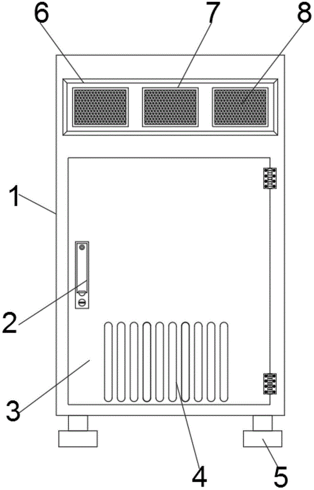
图1为本实用新型的整体结构示意图;Fig. 1 is the overall structure schematic diagram of the present utility model;
图2为本实用新型的内部结构示意图;Fig. 2 is the internal structure schematic diagram of the utility model;
图3为本实用新型的散热管结构示意图。FIG. 3 is a schematic diagram of the structure of the heat dissipation pipe of the present invention.
图中:1-制冷机主体、2-门锁、3-检修门、4-散热口、5-支撑脚、6-凹槽、7-进风口、8-过滤网、9-发热元器件、10-硅脂层、11-散热片、12-水箱、13-连接板、14-固定螺栓、15-进水口、16-进水管、17-增压泵、18-出水口、19-出水管、20-安装架、21-散热风扇、22-散热管、23-散热翅片、24-散热管出水口、25-散热管进水口。In the picture: 1- Refrigerator body, 2- door lock, 3- access door, 4- cooling vent, 5- supporting foot, 6- groove, 7- air inlet, 8- filter screen, 9- heating element, 10-Silicone grease layer, 11-Heat sink, 12-Water tank, 13-Connecting plate, 14-Fixing bolt, 15-Water inlet, 16-Water inlet pipe, 17-Booster pump, 18-Water outlet, 19-Water outlet pipe , 20-mounting frame, 21- cooling fan, 22- cooling pipe, 23- cooling fin, 24- cooling pipe water outlet, 25- cooling pipe water inlet.
具体实施方式Detailed ways
下面将结合本实用新型实施例中的附图,对本实用新型实施例中的技术方案进行清楚、完整地描述,显然,所描述的实施例仅仅是本实用新型一部分实施例,而不是全部的实施例,基于本实用新型中的实施例,本领域普通技术人员在没有做出创造性劳动前提下所获得的所有其他实施例,都属于本实用新型保护的范围。The technical solutions in the embodiments of the present utility model will be clearly and completely described below with reference to the accompanying drawings in the embodiments of the present utility model. Obviously, the described embodiments are only a part of the embodiments of the present utility model, rather than all the implementations. For example, based on the embodiments of the present invention, all other embodiments obtained by persons of ordinary skill in the art without creative work shall fall within the protection scope of the present invention.
请参阅图1-3,本实用新型提供一种技术方案:Please refer to Figures 1-3, the utility model provides a technical solution:
一种制冷设备用制冷机散热装置,包括制冷机主体1、水箱12和散热风扇21,制冷机主体1基面安装有检修门3,检修门3与制冷机主体1通过合页连接,检修门3一侧设有门锁2,检修门3底端开设有散热口4,检修门3上方设有凹槽6,凹槽6内设有多组进风口7,进风口7内部设有过滤网8,制冷机主体1底部固定安装有支撑脚5,支撑脚5共设有四组,且固定安装在制冷机主体1底部四个拐角处,制冷机主体1内部侧壁上设有发热元器件9,发热元器件9一侧设有散热片11,散热片11与发热元器件9之间设有硅脂层10,散热片11远离发热元器件9一侧设有水箱12,散热片11与水箱12固定连接,且连接处设有密封圈,散热片11置于水箱12的一侧设有微水道片,水箱12靠近散热片11的上下两端安装有连接板13,连接板13与发热元器件9通过固定螺栓14相连接,水箱12顶部设有进水口15,水箱12底部设有出水口18,制冷机主体1内部底端设有安装架20,安装架20基面安装有散热风扇21,散热风扇21外侧设有四组安装脚,且通过螺栓与安装架20固定连接,安装架20内部设有散热管22,散热管22上设有多组散热翅片23,散热管22一端设有散热管出水口24,散热管22另一端设有散热管进水口25,进水口15与散热管出水口24通过进水管16相连接,进水管16与散热管出水口24通过法兰连接,进水管16上设有增压泵17,出水口18与散热管进水口25通过出水管19相连接,出水管19与散热管进水口25通过法兰连接。A refrigerator cooling device for refrigeration equipment, comprising a refrigerator main body 1, a
本实用新型的工作流程:使用时,通过固定螺栓14将水箱12与发热元器件9连接,水箱12一侧的散热片11与制冷机内的发热元器件9贴合,且散热片11与发热元器件9之间设有硅脂层10,能帮助消除接触面的空气间隙增大热流通,减小热阻,将发热元器件9的工作温度传导到散热片11上,散热片11与水箱12固定连接,且散热片11置于水箱12的一侧设有微水道片,增加与水箱12中冷水的接触面积,将散热片11上吸收的温度更加快速的传导到水中,降低发热元器件9的工作温度,水箱12中的冷水吸收完散热片11上的温度后,会变成温水,通过出水管19,进入散热管22内,通过散热风扇21对散热管22内的温水进行散热,且散热管22设置成S形,增加了水在散热管22中的停留时间,散热管22上设有多组散热翅片23,加快将水中的热量导出,散热后的冷水通过进水管16和进水管16上的增压泵17进入水箱12,使得设备使用时,提高冷却水的散热速度,有效的提高散热效果,更好的帮助制冷机进行散热,保证制冷机的制冷效果,且稳定性和实用性较高,具有一定的推广价值。The working process of the utility model: when in use, the
尽管已经示出和描述了本实用新型的实施例,对于本领域的普通技术人员而言,可以理解在不脱离本实用新型的原理和精神的情况下可以对这些实施例进行多种变化、修改、替换和变型,本实用新型的范围由所附权利要求及其等同物限定。Although the embodiments of the present invention have been shown and described, it will be understood by those skilled in the art that various changes and modifications can be made to these embodiments without departing from the principles and spirit of the present invention , alternatives and modifications, the scope of the present invention is defined by the appended claims and their equivalents.
Claims (6)
Priority Applications (1)
| Application Number | Priority Date | Filing Date | Title |
|---|---|---|---|
| CN202020096760.8U CN211424839U (en) | 2020-01-16 | 2020-01-16 | Refrigerating machine heat abstractor for refrigeration plant |
Applications Claiming Priority (1)
| Application Number | Priority Date | Filing Date | Title |
|---|---|---|---|
| CN202020096760.8U CN211424839U (en) | 2020-01-16 | 2020-01-16 | Refrigerating machine heat abstractor for refrigeration plant |
Publications (1)
| Publication Number | Publication Date |
|---|---|
| CN211424839U true CN211424839U (en) | 2020-09-04 |
Family
ID=72275033
Family Applications (1)
| Application Number | Title | Priority Date | Filing Date |
|---|---|---|---|
| CN202020096760.8U Expired - Fee Related CN211424839U (en) | 2020-01-16 | 2020-01-16 | Refrigerating machine heat abstractor for refrigeration plant |
Country Status (1)
| Country | Link |
|---|---|
| CN (1) | CN211424839U (en) |
Cited By (1)
| Publication number | Priority date | Publication date | Assignee | Title |
|---|---|---|---|---|
| CN112503750A (en) * | 2020-12-03 | 2021-03-16 | 苏州市朗吉科技有限公司 | Auxiliary heat dissipation device for precise air conditioner of machine room |
-
2020
- 2020-01-16 CN CN202020096760.8U patent/CN211424839U/en not_active Expired - Fee Related
Cited By (1)
| Publication number | Priority date | Publication date | Assignee | Title |
|---|---|---|---|---|
| CN112503750A (en) * | 2020-12-03 | 2021-03-16 | 苏州市朗吉科技有限公司 | Auxiliary heat dissipation device for precise air conditioner of machine room |
Similar Documents
| Publication | Publication Date | Title |
|---|---|---|
| CN102819303A (en) | Computer case | |
| WO2018098911A1 (en) | Partial immersion liquid-cooling system for cooling server | |
| CN208999940U (en) | A computer water cooling system based on dual mainboard structure | |
| CN106051956A (en) | Electric controller based on heat-superconducting cooling plate, and outdoor unit of air conditioner | |
| CN207219278U (en) | A kind of electrical equipment and its radiator structure | |
| CN112152119A (en) | Closed power distribution cabinet high frequency anti-aging heat sink | |
| CN206946407U (en) | A kind of computer water-cooling radiating device | |
| CN206312059U (en) | Processor heat abstractor | |
| CN108131862A (en) | A kind of high miniature thermoelectric refrigerator of security performance | |
| CN212138204U (en) | A computer network switch cooling device | |
| CN206059322U (en) | A kind of heat abstractor of chopper | |
| CN218163405U (en) | Radiator of power box | |
| CN219590784U (en) | Water cooling structure of central processing unit | |
| CN216527067U (en) | Water-cooling row with semiconductor refrigerating sheet | |
| CN216897939U (en) | Anti-freezing device for water chiller | |
| CN206147501U (en) | computer cooler | |
| CN204830957U (en) | Big big wave type runner antipollution heat exchanger of tooth pitch | |
| CN209514541U (en) | A kind of Cloud Server heat radiation rack for computer internet | |
| CN221802110U (en) | Device for improving refrigeration energy efficiency ratio of silicone oil cooler | |
| CN211240568U (en) | A heat sink for electronic equipment | |
| CN114510135A (en) | Temperature-uniforming plate with good heat conduction and heat dissipation effects | |
| CN209345488U (en) | A kind of radiator for semiconductor equipment | |
| CN221884259U (en) | A water-cooled radiator with cooling fins | |
| CN223024783U (en) | A heat dissipation device for electromechanical equipment | |
| CN218784034U (en) | Heat abstractor for OTN optical transmission equipment |
Legal Events
| Date | Code | Title | Description |
|---|---|---|---|
| GR01 | Patent grant | ||
| GR01 | Patent grant | ||
| CF01 | Termination of patent right due to non-payment of annual fee |
Granted publication date: 20200904 Termination date: 20210116 |
|
| CF01 | Termination of patent right due to non-payment of annual fee |