CN211414169U - Welding set for electrical engineering - Google Patents
Welding set for electrical engineering Download PDFInfo
- Publication number
- CN211414169U CN211414169U CN201922248963.4U CN201922248963U CN211414169U CN 211414169 U CN211414169 U CN 211414169U CN 201922248963 U CN201922248963 U CN 201922248963U CN 211414169 U CN211414169 U CN 211414169U
- Authority
- CN
- China
- Prior art keywords
- welding
- platform
- moving block
- electrical engineering
- limiting
- Prior art date
- Legal status (The legal status is an assumption and is not a legal conclusion. Google has not performed a legal analysis and makes no representation as to the accuracy of the status listed.)
- Expired - Fee Related
Links
Images


Landscapes
- Butt Welding And Welding Of Specific Article (AREA)
Abstract
The utility model relates to a welding device for electrical engineering, which comprises a platform, a stand column and a welding device, the upright post is vertically arranged on the platform, the welding device is fixedly arranged on the upright post, the platform is fixedly provided with a welding table, the top wall of the welding table is provided with an accommodating groove along the vertical direction, two ends of the accommodating groove are provided with openings, a working plate is arranged in the accommodating groove in a sliding manner, a driving piece for driving the working plate to move up and down is fixedly arranged on the welding table, the top wall of the welding table is fixedly provided with a bracket, the bracket is provided with a clamping device for fixing a workpiece, the platform is provided with an accommodating box, the accommodating box is arranged at one end close to the opening of the accommodating box, the working plate is provided with a scraper in a sliding way, the diapire of scraper blade and the roof butt of working plate, be provided with the drive assembly who is used for ordering about the scraper blade and moves along the length direction of holding tank on the welding bench. Has the effect of conveniently cleaning welding slag.
Description
Technical Field
The utility model belongs to the technical field of electrical engineering welding equipment technique and specifically relates to a welding set for electrical engineering is related to.
Background
Electrical engineering is one of the core disciplines in the modern science and technology field, and is an indispensable key discipline in the high-tech electrical engineering field nowadays. Welding is the process of joining metal parts using various fusible alloys (solders). The melting point of the solder is lower than that of the material to be welded, so that the welding is completed by intermolecular connection between the surfaces of the parts without melting the parts. The traditional welding operation is mainly manual welding, the labor intensity of the manual welding is high, and the working efficiency is low.
The patent with the publication number of CN208734667U discloses a welding device for electrical engineering, which comprises a base, wherein a support pillar is arranged on the base, vertical plates are arranged on the left side and the right side of the rear end face of the support pillar, a longitudinal driving motor is arranged above the vertical plates on the rear end face of the support pillar, the output end of the longitudinal driving motor is downwards arranged and connected with one end of a longitudinal screw rod, the other end of the longitudinal screw rod is fixedly connected with a first stop block, the first stop block is fixedly arranged on the rear end face of the support pillar, a cross beam is rotatably connected to the longitudinal screw rod, transverse plates are arranged on the upper side and the lower side of the rear end face of the cross beam, a transverse driving motor is arranged between the transverse plates on the rear end face of the cross beam in a right-side installation manner, the output end of the transverse driving motor is, the transverse screw rod is rotatably connected with a welding plate, and the welding plate is provided with a welding head. During welding, the longitudinal driving motor is started to control the cross beam arranged on the longitudinal screw rod to move up and down, so that the distance between the welding head and the welding part in the vertical direction is adjusted, the transverse driving motor is started to control the welding plate arranged on the transverse screw rod, the horizontal distance between the welding head and the welding part can be adjusted, and the welding head can move front and back, left and right and up and down in all directions.
The above prior art solutions have the following drawbacks: welding slag can be generated in the welding process of workpieces, the welding slag splashes around and is scattered around on a welding table, manual cleaning is needed, and cleaning is very inconvenient.
SUMMERY OF THE UTILITY MODEL
Aiming at the defects existing in the prior art, one of the purposes of the utility model is to provide a welding device for electrical engineering, which has the advantage of conveniently cleaning welding slag.
The above utility model discloses an above-mentioned utility model purpose can realize through following technical scheme: a welding device for electrical engineering comprises a platform, an upright post and a welding device, wherein the upright post is vertically arranged on the platform, the welding device is fixedly arranged on the upright post, the welding table is fixedly arranged on the platform, the top wall of the welding table is provided with a containing groove along the vertical direction, the two ends of the containing groove are provided with openings, the containing groove is internally provided with a working plate in a sliding way, the welding table is fixedly provided with a driving piece for driving the working plate to move up and down, the top wall of the welding table is fixedly provided with a bracket, the bracket is provided with a clamping device for fixing a workpiece, the platform is provided with an accommodating box, the accommodating box is arranged at one end close to the opening of the accommodating box, the working plate is provided with a scraper in a sliding way, the diapire of scraper blade and the roof butt of working plate, be provided with the drive assembly who is used for ordering about the scraper blade and moves along the length direction of holding tank on the welding bench.
By adopting the technical scheme, when a workpiece is welded, the workpiece is placed on the working plate, the clamping device is used for fixing the position of the workpiece, then the welding device is used for welding the workpiece, and welding slag generated in the welding process is scattered on the working plate of the welding table. After the welding is finished, the driving piece is started to drive the working plate to move downwards. The working plate moves down and stops the driving piece after a certain distance, then starts drive assembly and orders about the scraper blade and hold the case and remove along the holding tank orientation, and after the scraper blade removed to holding the case top, the drive assembly that stops can realize that the scraper blade clears up the welding slag on the working plate to the purpose that holds the incasement, convenient operation.
The present invention may be further configured in a preferred embodiment as: the driving assembly comprises a driving motor, a lead screw and a moving block, frames are fixedly arranged on two sides of the welding table, the lead screw is rotatably arranged on the frames, an output shaft of the driving motor is coaxially and fixedly connected with the lead screw, threads of the moving block are rotatably arranged on the lead screw, and the scraper is arranged on the moving block.
Through adopting above-mentioned technical scheme, when clearing up the welding slag, start driving motor, driving motor's output shaft rotates, drives the lead screw and rotates, and the screw thread sets up the movable block on the lead screw and removes along the length direction of holding tank, and the scraper blade on the movable block holds the case motion along with it, can realize that the scraper blade clears up the welding slag on the working plate to the purpose that holds the incasement, convenient operation.
The present invention may be further configured in a preferred embodiment as: the side wall of the moving block, which is close to the containing box, is provided with a T-shaped sliding groove along the length direction of the containing groove, the scraper is fixedly provided with a T-shaped sliding block matched with the T-shaped sliding groove, and the moving block is provided with a limiting part for limiting the position of the scraper.
Through adopting above-mentioned technical scheme, the cooperation of T type spout and T type slider realizes being connected dismantled of movable block and scraper blade, is convenient for change the scraper blade. The position of the scraper blade is fixed to the locating part, and the scraper blade is effectively prevented from sliding out of the T-shaped sliding groove.
The present invention may be further configured in a preferred embodiment as: the limiting part is a limiting pin, a limiting hole penetrating to the T-shaped sliding groove is formed in the side wall of the moving block, the limiting hole is formed in the side wall close to the containing groove, the limiting pin penetrates through the limiting hole and the T-shaped sliding groove in a sliding mode, a round table is fixedly arranged at one end, away from the limiting T-shaped sliding groove, of the limiting pin, and a spring is sleeved on the limiting pin; one end of the spring is fixedly connected with the side wall, close to the containing groove, of the moving block, and the other end of the spring is fixedly connected with the side wall, close to the moving block, of the circular truncated cone.
By adopting the technical scheme, when the scraper is installed on the moving block, the round platform is pinched to draw out the limiting pin outwards, the spring is compressed, then the T-shaped sliding block on the scraper slides into the T-shaped sliding groove, the round platform is loosened, the limiting pin is automatically inserted into the T-shaped sliding groove by the elastic force generated by the spring, the scraper can be positioned, the scraper is effectively prevented from being separated from the T-shaped sliding groove, and the operation is convenient.
The present invention may be further configured in a preferred embodiment as: one end of the welding table close to the containing box is provided with a guide inclined plate.
Through adopting above-mentioned technical scheme, the direction swash plate is convenient for the scraper blade and scrapes the welding slag to holding in the case from the working plate.
The present invention may be further configured in a preferred embodiment as: the two sides of the welding table are provided with baffles, and the length directions of the baffles are parallel to the axial direction of the screw rod.
By adopting the technical scheme, the baffle plate effectively prevents welding slag from splashing everywhere in the process of welding workpieces, and the safety of welding personnel is improved.
The present invention may be further configured in a preferred embodiment as: the fixed block that is provided with on the platform, the through-hole has been seted up along the axial of lead screw to the lateral wall of fixed block, the through-hole internal rotation is provided with the dwang, dwang and baffle fixed connection, the length direction of dwang is parallel with the length direction of baffle, the fixed servo motor that is provided with on the platform, servo motor's output shaft and the coaxial fixed connection of dwang.
Through adopting above-mentioned technical scheme, press from both sides tight work piece after, start servo motor and order about the dwang and rotate, set up baffle on the dwang and rotate thereupon, when baffle and welding bench butt, close servo motor, can use the welding dress welding work piece, the baffle can effectively prevent that the welding slag from splashing everywhere.
The present invention may be further configured in a preferred embodiment as: the clamping device comprises a bidirectional screw rod and two clamping blocks, the bidirectional screw rod is rotatably arranged on the support, the clamping blocks are rotatably arranged on the bidirectional screw rod in a threaded manner, and a hand wheel is fixedly arranged at one end of the bidirectional screw rod.
By adopting the technical scheme, when the clamping device is used for clamping a workpiece, the workpiece is placed between the two clamping blocks. And the hand wheel is rotated, the bidirectional screw rod rotates on the bracket, and the two clamping blocks in threaded connection on the bidirectional screw rod move close to each other. After the clamping block clamps the workpiece, the handle is loosened, and then the subsequent welding step can be carried out, so that the operation is convenient.
To sum up, the utility model discloses a following at least one useful technological effect:
1. the driving assembly drives the scraper plate to move towards the containing box, and the scraper plate scrapes the welding slag on the working plate to the containing box, so that the purpose of cleaning the welding slag can be achieved, and the operation is convenient;
2. the T-shaped sliding groove is matched with the T-shaped sliding block to realize the disassembly of the scraper and the moving block, so that the replacement of the scraper is facilitated;
3. the setting of baffle effectively prevents that welding slag from splashing everywhere, has improved welding personnel's security.
Drawings
Fig. 1 is a schematic view of the overall structure of the present invention.
Fig. 2 is an exploded view of fig. 1.
Fig. 3 is a schematic view of the structure of the moving block.
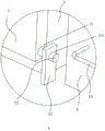
Fig. 4 is an enlarged view of a portion a in fig. 1.
Reference numerals: 1. a platform; 11. a first cylinder; 12. a support table; 121. a servo motor; 13. a base; 131. a drive motor; 2. a column; 21. a second cylinder; 22. a welding device; 221. a cross beam; 222. welding a head; 3. a welding table; 31. accommodating grooves; 311. a third cylinder; 32. a working plate; 321. a guide sloping plate; 322. a stopper; 4. a support; 41. perforating; 42. a bidirectional lead screw; 421. a hand wheel; 43. a clamping block; 5. a baffle plate; 51. mounting holes; 52. rotating the rod; 53. a fixed block; 531. a through hole; 6. an accommodating box; 61. a handle; 7. a frame; 71. a screw rod; 72. a moving block; 721. a T-shaped chute; 722. a limiting hole; 723. a threaded hole; 73. a squeegee; 731. a brush; 732. a T-shaped slider; 74. a spacing pin; 741. a circular truncated cone; 742. a spring.
Detailed Description
The present invention will be described in further detail with reference to the accompanying drawings.
Referring to fig. 1, for the utility model discloses a welding set for electrical engineering, including platform 1 and stand 2, platform 1 goes up vertical fixed first cylinder 11 that is provided with, and the vertical fixed setting of stand 2 is on the piston rod of first cylinder 11, and the stand 2 is gone up the fixed second cylinder 21 that is provided with of level, and the fixed welding set 22 that is provided with of level is gone up to the piston rod of second cylinder 21. The welding device 22 comprises a beam 221 and a welding head 222, the beam 221 is coaxially and fixedly connected with the piston rod of the second cylinder 21, and the welding head 222 is vertically and fixedly arranged on the beam 221. The arrangement of the first cylinder 11 and the second cylinder 21 realizes the movement of the welding head 222 in the up-down direction and the left-right direction, and the operation is convenient.
Referring to fig. 1 and 2, a welding table 3 is fixedly arranged on the platform 1, and the welding table 3 is a rectangular parallelepiped. Holding tank 31 has been seted up along vertical direction to the roof of welding bench 3, and the both ends opening of holding tank 31 sets up. The bottom wall of the accommodating groove 31 is vertically and fixedly provided with a third cylinder 311, and a working plate 32 is horizontally arranged in the accommodating groove 31. The lateral wall of working plate 32 and the lateral wall butt of holding tank 31, the perpendicular fixed connection of the piston rod of third cylinder 311 and the diapire of working plate 32, the setting of third cylinder 311 realizes the lift of working plate 32. A guide inclined plate 321 is fixedly provided at one end of the operating plate 32 close to the accommodating box 6, and the guide inclined plate 321 is inclined toward the center of the accommodating box 6. Both sides wall of direction swash plate 321 all is fixed and is provided with dog 322, and dog 322 is perpendicular with direction swash plate 321. The direction swash plate 321 is convenient for the welding slag to get into and holds case 6, and dog 322 prevents effectively that the welding slag from the both sides landing of direction swash plate 321.
Referring to fig. 1 and 2, a support 4 is vertically and fixedly arranged on the top wall of the welding table 3, through holes 41 are formed in the support 4 along the width direction of the welding plate, and a bidirectional screw 42 is rotatably arranged in the through holes 41. The two-way screw rod 42 is provided with two clamping blocks 43 in a threaded rotation mode, and the two clamping blocks 43 are respectively arranged at two ends of the two-way screw rod 71 in a threaded rotation mode, wherein the thread turning directions of the two ends are opposite. A hand wheel 421 is fixedly arranged at one end of the bidirectional screw 42. The two-way screw rod 42 is rotated by using the hand wheel 421, and the two clamping blocks 43 approach each other, so that the workpiece can be clamped.
Referring to fig. 1 and 4, the two sides of the welding table 3 are vertically provided with the baffle plates 5, the baffle plates 5 effectively prevent welding slag from splashing everywhere, and the safety of welding personnel is improved. The lateral wall of baffle 5 sets up the mounting hole 51 that runs through baffle 5 along the length direction of welding bench 3, wears to be equipped with dwang 52 in the mounting hole 51, dwang 52 and baffle 5 fixed connection. The fixed block 53 is fixedly arranged on the platform 1, a through hole 531 is formed in the side wall of the fixed block 53 along the length direction of the welding table 3, and the rotating rod 52 is rotatably arranged in the through hole 531 in a penetrating manner. A supporting table 12 is fixedly arranged on the platform 1, a servo motor 121 is horizontally and fixedly arranged on the top wall of the supporting table 12, and the output shaft of the servo motor 121 is coaxially and fixedly connected with one end, far away from the fixing block 53, of the rotating rod 52. The servo motor 121 is used for driving the rotating rod 52 to rotate, so that the baffle 5 is turned over, and the operation of welding personnel is facilitated.
Referring to fig. 1, the platform 1 is provided with a containing box 6, the containing box 6 is a rectangular parallelepiped, and the length of the containing box 6 is greater than the width of the containing groove 31. The accommodating box 6 is provided near the opening of the accommodating groove 31, and one end of the inclined guide plate 321 remote from the work plate 32 is located above the accommodating box 6. A handle 61 is fixedly provided to a side wall of the accommodating case 6. The containing box 6 is used for collecting welding slag, and the handle 61 is arranged to facilitate the movement of the containing box 6. One side that welding bench 3 is close to and holds case 6 is provided with frame 7, and frame 7 is vertical fixed to be set up on platform 1, and the level is rotated on frame 7 and is provided with lead screw 71. One side that frame 7 was kept away from to welding bench 3 is provided with base 13, and base 13 is vertical fixed to be set up on platform 1. A driving motor 131 is horizontally and fixedly arranged on the base 13, and an output shaft of the driving motor 131 is coaxially and fixedly connected with the screw rod 71.
Referring to fig. 2 and 3, a moving block 72 is provided on the frame 7, a threaded hole 723 matched with the lead screw 71 is formed in a side wall of the moving block 72 along the length direction of the welding table 3, the moving block 72 is rotatably provided on the lead screw 71 by a thread, and a scraper 73 is provided on the moving block 72. The driving motor 131 drives the screw rod 71 to rotate, and then the moving block 72 can be driven to move along the horizontal direction, so that the welding slag can be cleaned by the scraper 73, and the operation is convenient. The side wall of the moving block 72 close to the accommodating box 6 is provided with a T-shaped sliding groove 721 along the length direction of the accommodating groove 31, the top wall of the scraper 73 is fixedly provided with a T-shaped slider 732 matched with the T-shaped sliding groove 721, and the T-shaped slider 732 is slidably arranged in the T-shaped sliding groove 721. The side wall of the moving block 72 close to the baffle 5 is provided with a limiting hole 722 penetrating through the T-shaped sliding slot 721 along the width direction of the accommodating groove 31, and a limiting pin 74 is slidably arranged in the limiting hole 722. A circular truncated cone 741 is fixedly arranged at one end of the limiting pin 74 far away from the limiting T-shaped sliding groove 721, and a spring 742 is sleeved on the limiting pin 74; one end of the spring 742 is fixedly connected to the side wall of the moving block 72 close to the stationary plate 5, and the other end is fixedly connected to the side wall of the circular truncated cone 741 close to the moving block 72. The bottom wall of scraper 73 is vertical fixed and is provided with brush 731, and when scraper 73 cleared up the welding slag, brush 731 and the roof of working plate 32 butt. The T-shaped sliding grooves 721 are matched with the T-shaped sliding blocks 732 to detach the moving block 72 from the scraping plate 73, so that the scraping plate 73 is convenient to replace and detach. The limiting pin 74 effectively prevents the scraping plate 73 from sliding down from the T-shaped chute 721, and the spring 742 is provided to facilitate the limiting pin 74 to limit the scraping plate 73.
The implementation principle of the embodiment is as follows: when welding a workpiece, the workpiece is placed on the working plate 32, the hand wheel 421 is held to rotate the bidirectional screw rod 42 on the bracket 4, and the two clamping blocks 43 move close to each other. After the workpiece is clamped by the clamping block 43, the first cylinder 11 and the second cylinder 21 are adjusted to enable the welding head 222 to be close to the welding position of the workpiece, and then welding is started. After the welding is completed, the third cylinder 311 is actuated to lower the height of the work plate 32, and then the operation is stopped. The driving motor 131 is started to drive the lead screw 71 to rotate, the moving block 72 on the lead screw 71 moves along the length direction of the accommodating groove 31, and the scraper 73 arranged on the moving block 72 moves towards the accommodating box 6. When the scraper 73 moves to one end of the working plate 32 close to the containing box 6, the driving motor 131 is turned off, so that the purpose of cleaning welding slag can be achieved, and the operation is convenient.
The embodiment of this specific implementation mode is the preferred embodiment of the present invention, not limit according to this the utility model discloses a protection scope, so: all equivalent changes made according to the structure, shape and principle of the utility model are covered within the protection scope of the utility model.
Claims (8)
1. The utility model provides a welding set for electrical engineering, includes platform (1), stand (2) and welding set (22), stand (2) are vertical to be set up on platform (1), welding set (22) are fixed to be set up on stand (2), its characterized in that: the welding table (3) is fixedly arranged on the platform (1), the top wall of the welding table (3) is provided with a containing groove (31) along the vertical direction, the two ends of the accommodating groove (31) are provided with openings, the accommodating groove (31) is internally provided with a working plate (32) in a sliding way, a driving piece for driving the working plate (32) to move up and down is fixedly arranged on the welding table (3), a bracket (4) is fixedly arranged on the top wall of the welding table (3), a clamping device for fixing a workpiece is arranged on the bracket (4), the platform (1) is provided with an accommodating box (6), the accommodating box (6) is arranged close to one end of the opening of the accommodating groove (31), the working plate (32) is provided with a scraper (73) in a sliding mode, and the welding table (3) is provided with a driving assembly used for driving the scraper (73) to move along the length direction of the accommodating groove (31).
2. The welding device for electrical engineering according to claim 1, wherein: the driving assembly comprises a driving motor (131), a lead screw (71) and a moving block (72), racks (7) are fixedly arranged on two sides of the welding table (3), the lead screw (71) is rotatably arranged on the racks (7), an output shaft of the driving motor (131) is coaxially and fixedly connected with the lead screw (71), the moving block (72) is rotatably arranged on the lead screw (71) in a threaded manner, and the scraper (73) is arranged on the moving block (72).
3. The welding device for electrical engineering according to claim 2, wherein: the side wall of the moving block (72) close to the containing box (6) is provided with a T-shaped sliding groove (721) along the length direction of the containing groove (31), the scraping plate (73) is fixedly provided with a T-shaped sliding block (732) matched with the T-shaped sliding groove (721), and the moving block (72) is provided with a limiting piece for limiting the position of the scraping plate (73).
4. The welding device for electrical engineering according to claim 3, wherein: the limiting piece is a limiting pin (74), a limiting hole (722) penetrating through the T-shaped sliding groove (721) is formed in the side wall of the moving block (72), the limiting hole (722) is formed in the side wall, close to the accommodating groove (31), of the limiting block, the limiting pin (74) penetrates through the limiting hole (722) and the T-shaped sliding groove (721) in a sliding mode, a circular truncated cone (741) is fixedly arranged at one end, far away from the limiting T-shaped sliding groove (721), of the limiting pin (74), and a spring (742) is sleeved on the limiting pin (74); one end of the spring (742) is fixedly connected with the side wall, close to the accommodating groove (31), of the moving block (72), and the other end of the spring is fixedly connected with the side wall, close to the moving block (72), of the circular truncated cone (741).
5. The welding device for electrical engineering according to claim 1, wherein: one end of the welding table (3) close to the containing box (6) is provided with a guide sloping plate (321).
6. The welding device for electrical engineering according to claim 1, wherein: the two sides of the welding table (3) are provided with baffle plates (5), and the length direction of the baffle plates (5) is parallel to the axial direction of the screw rod (71).
7. The welding device for electrical engineering according to claim 6, wherein: fixed block (53) of being provided with on platform (1), through-hole (531) have been seted up along the axial of lead screw (71) to the lateral wall of fixed block (53), through-hole (531) internal rotation is provided with dwang (52), dwang (52) and baffle (5) fixed connection, the length direction of dwang (52) is parallel with the length direction of baffle (5), fixed servo motor (121) of being provided with on platform (1), the output shaft and the coaxial fixed connection of dwang (52) of servo motor (121).
8. The welding device for electrical engineering according to claim 1, wherein: the clamping device comprises a bidirectional screw rod (42) and two clamping blocks (43), the bidirectional screw rod (42) is rotatably arranged on the support (4), the clamping blocks (43) are rotatably arranged on the bidirectional screw rod (42) in a threaded manner, and a hand wheel (421) is fixedly arranged at one end of the bidirectional screw rod (42).
Priority Applications (1)
| Application Number | Priority Date | Filing Date | Title |
|---|---|---|---|
| CN201922248963.4U CN211414169U (en) | 2019-12-16 | 2019-12-16 | Welding set for electrical engineering |
Applications Claiming Priority (1)
| Application Number | Priority Date | Filing Date | Title |
|---|---|---|---|
| CN201922248963.4U CN211414169U (en) | 2019-12-16 | 2019-12-16 | Welding set for electrical engineering |
Publications (1)
| Publication Number | Publication Date |
|---|---|
| CN211414169U true CN211414169U (en) | 2020-09-04 |
Family
ID=72250336
Family Applications (1)
| Application Number | Title | Priority Date | Filing Date |
|---|---|---|---|
| CN201922248963.4U Expired - Fee Related CN211414169U (en) | 2019-12-16 | 2019-12-16 | Welding set for electrical engineering |
Country Status (1)
| Country | Link |
|---|---|
| CN (1) | CN211414169U (en) |
Cited By (5)
| Publication number | Priority date | Publication date | Assignee | Title |
|---|---|---|---|---|
| CN112108820A (en) * | 2020-09-15 | 2020-12-22 | 合肥市东庐机械制造有限公司 | Finish machining of fork truck accessory sprocket seat is with assembly welding device |
| CN113263262A (en) * | 2021-05-30 | 2021-08-17 | 孙明元 | Copper-aluminum laser welding machine and use method thereof |
| CN113560775A (en) * | 2021-08-24 | 2021-10-29 | 镇江奥博电力设备有限公司 | Welding equipment for electric heater machining and using method thereof |
| CN114083204A (en) * | 2021-10-23 | 2022-02-25 | 四川银桥钢模有限公司 | Steel formwork welding platform and welding method |
| CN117139943A (en) * | 2023-10-30 | 2023-12-01 | 南通汉腾建筑科技有限公司 | Steel structure protection component |
-
2019
- 2019-12-16 CN CN201922248963.4U patent/CN211414169U/en not_active Expired - Fee Related
Cited By (7)
| Publication number | Priority date | Publication date | Assignee | Title |
|---|---|---|---|---|
| CN112108820A (en) * | 2020-09-15 | 2020-12-22 | 合肥市东庐机械制造有限公司 | Finish machining of fork truck accessory sprocket seat is with assembly welding device |
| CN113263262A (en) * | 2021-05-30 | 2021-08-17 | 孙明元 | Copper-aluminum laser welding machine and use method thereof |
| CN113560775A (en) * | 2021-08-24 | 2021-10-29 | 镇江奥博电力设备有限公司 | Welding equipment for electric heater machining and using method thereof |
| CN113560775B (en) * | 2021-08-24 | 2022-12-13 | 镇江奥博电力设备有限公司 | Welding equipment for processing electric heater and using method thereof |
| CN114083204A (en) * | 2021-10-23 | 2022-02-25 | 四川银桥钢模有限公司 | Steel formwork welding platform and welding method |
| CN117139943A (en) * | 2023-10-30 | 2023-12-01 | 南通汉腾建筑科技有限公司 | Steel structure protection component |
| CN117139943B (en) * | 2023-10-30 | 2024-01-26 | 南通汉腾建筑科技有限公司 | Steel structure protection component |
Similar Documents
| Publication | Publication Date | Title |
|---|---|---|
| CN211414169U (en) | Welding set for electrical engineering | |
| CN210649235U (en) | Electric welding machine capable of quickly clamping workpieces with different sizes | |
| CN110918615B (en) | Device for removing electronic elements of waste electronic circuit boards | |
| CN214392947U (en) | Novel member welding control machine device | |
| CN111318521A (en) | Gantry type slag removing device for metal submerged arc additive | |
| CN110814479A (en) | Automatic welding device and welding method for three-wave circular pipe anti-blocking submerged arc welding | |
| CN211866846U (en) | Slag knocking and removing device for metal submerged arc material increase | |
| CN218891549U (en) | Lathe convenient to clearance | |
| CN207104065U (en) | A kind of automatic soldering device | |
| CN213318253U (en) | Quick plasma cutting device of electromechanical accessory | |
| CN213945397U (en) | Welding device with protection function for electrical cabinet production | |
| CN114833400A (en) | Device for removing slag and burrs of pipe | |
| CN209868636U (en) | Material taking arm assembly for full-automatic tooth welding machine manipulator | |
| CN212635157U (en) | Fastener cutting device with safeguard function | |
| CN111644793A (en) | Automobile punching part welding jig positioner | |
| CN219053315U (en) | Part welding device | |
| CN211072022U (en) | Multidirectional cutting device for saw cutting of guide rod | |
| CN219966908U (en) | Tension spring type clamping assembly of welding workbench | |
| CN213410761U (en) | Pedal type spot welding machine | |
| CN209773853U (en) | Manipulator for full-automatic gear welding machine | |
| CN219786657U (en) | Drilling device | |
| CN219521441U (en) | Automatic chip cleaning device for engraving machine | |
| CN215966717U (en) | Building material cutting device for building site | |
| CN220718677U (en) | Angle-adjustable mechanical drilling device | |
| CN219924988U (en) | Explosion vent welding set |
Legal Events
| Date | Code | Title | Description |
|---|---|---|---|
| GR01 | Patent grant | ||
| GR01 | Patent grant | ||
| CF01 | Termination of patent right due to non-payment of annual fee |
Granted publication date: 20200904 Termination date: 20211216 |
|
| CF01 | Termination of patent right due to non-payment of annual fee |