CN211414167U - Automatic assembling device for production of medium-heavy welded H-shaped steel - Google Patents
Automatic assembling device for production of medium-heavy welded H-shaped steel Download PDFInfo
- Publication number
- CN211414167U CN211414167U CN201922199016.0U CN201922199016U CN211414167U CN 211414167 U CN211414167 U CN 211414167U CN 201922199016 U CN201922199016 U CN 201922199016U CN 211414167 U CN211414167 U CN 211414167U
- Authority
- CN
- China
- Prior art keywords
- shaped
- top surface
- shaped steel
- template
- plate
- Prior art date
- Legal status (The legal status is an assumption and is not a legal conclusion. Google has not performed a legal analysis and makes no representation as to the accuracy of the status listed.)
- Expired - Fee Related
Links
Images

Abstract
The utility model provides a well heavy welding H shaped steel production is with automatic assembly device, includes the base, and the top surface four corners of base is fixed mounting stand respectively, and the front and back relative stand passes through connecting rod fixed connection, the equal fixed mounting second L template in inboard top of second pneumatic cylinder hydraulic stem, and the outside of first L template passes through the several extension spring with the slider that corresponds to be connected, the one end and the power device fixed connection of screw rod. The user can control hydraulic motor work through the controller to interval when adjusting the vertical state of first L template can adapt to the pterygoid lamina of different width, and can be through the controller opening the extension or the shrink of second pneumatic cylinder hydraulic stem, adjust the height of second L template, thereby adapt to the not web of co-altitude, the utility model discloses can adapt to not unidimensional web and pterygoid lamina, application range is wide.
Description
Technical Field
The utility model belongs to automatic assembly device field, specifically speaking are automatic assembly device is used in production of well heavy welding H shaped steel.
Background
In the production process of H-shaped steel, assembling work needs to be carried out on a web plate and a wing plate of the H-shaped steel firstly, the web plate and the wing plate are conveyed into a welding device by a conveying device to be welded after the assembly is finished, the web plate is horizontally hoisted on the conveying device in the conventional H-shaped steel production line, one wing plate is vertically arranged on the top surface of the web plate through the assembling device to form a T-shaped structure, the T-shaped structure is conveyed into the welding device by the conveying device to be welded for the first time, after the welding is finished, a workpiece of the T-shaped structure and the other wing plate are conveyed to another production line by the conveying device to be assembled into the H-shaped structure through the assembling device, the H-shaped steel is conveyed into the corresponding welding device again to be welded, the H-shaped steel is finally obtained through.
SUMMERY OF THE UTILITY MODEL
The utility model provides a well heavy welding H shaped steel production is with automatic assembly device for solve the defect among the prior art.
The utility model discloses a following technical scheme realizes:
an automatic assembling device for medium-heavy welding H-shaped steel production comprises a base, wherein stand columns are fixedly installed at four corners of the top surface of the base respectively, the front stand column and the rear stand column are fixedly connected through a connecting rod, grooves are formed in the top surface of the connecting rod respectively, racks are fixedly installed on the bottom surfaces of the grooves, a plurality of strip-shaped plates are arranged above the base, tooth grooves are formed in two sides of the bottom surfaces of the strip-shaped plates respectively, rotating shafts are installed in the tooth grooves respectively through bearings, gears are fixedly installed on the peripheries of the rotating shafts respectively and are meshed with the corresponding racks, through holes are formed in one sides of the strip-shaped plates and are communicated with the tooth grooves on the same side, a controller with a control panel is fixedly installed on the periphery of one of the stand columns, a motor is fixedly installed on one side of each strip-shaped plate, an output shaft, the screw rod both ends are connected with the inboard bearing of the connecting plate that corresponds respectively, the screw thread opposite direction of screw rod central line both sides, the spout is seted up to the top surface of bar shaped plate, the spout is located between two connecting plates, the both sides difference movable mounting slider of spout, screw rod is seted up respectively to one side of slider passes in the screw, and screw-thread fit with it, the inboard articulated first L template of installation of top surface of slider, first L template sets up relatively, the inboard upper portion of the vertical board of first L template is the first pneumatic cylinder of fixed mounting respectively, the top surface of first L template is the fixed mounting second pneumatic cylinder respectively, the inboard top of second pneumatic cylinder hydraulic stem is the equal fixed mounting second L template, the outside and the slider that correspond of first L template pass through the several extension spring and are connected, the one end and the power device fixed connection of.
According to the automatic assembling device for medium and heavy welding H-shaped steel production, the power device is a hydraulic motor, the hydraulic motor is fixedly installed on one side of the top surface of the strip-shaped plate, and an output shaft of the hydraulic motor is fixedly connected with one end of the screw.
According to the automatic assembling device for medium and heavy welded H-shaped steel production, the end parts of the hydraulic rods of the first hydraulic cylinders are fixedly provided with the push plates.
According to the automatic assembling device for medium and heavy welding H-shaped steel production, the rubber pad is fixedly installed on the top surface of the sliding block.
According to the automatic assembling device for producing the medium and heavy type welding H-shaped steel, lubricating oil is smeared in the sliding groove.
According to the automatic assembling device for medium and heavy type welding H-shaped steel production, the U-shaped frames are fixedly installed on two sides of the bottom surface of the strip-shaped plate respectively, two ends of each U-shaped frame are fixedly connected with the bottom surface of the strip-shaped plate respectively, and the U-shaped frames are sleeved on the peripheries of the corresponding connecting rods respectively.
The utility model has the advantages that: the utility model is arranged below a welding device when in use, the welding device is the prior art, the concrete structure and the working process are not described in detail, for example, a five-degree-of-freedom welding and cutting robot with Chinese patent No. CN201510434953.3, a plurality of welding devices can be respectively arranged on two sides of the utility model, when the assembly of H-shaped steel is not carried out and the wing plate is not contacted with the first L-shaped plate, the first L-shaped plate is in an outward inclined state, as shown by dotted lines in the figure, and the motor, the hydraulic motor, the first hydraulic cylinder and the second hydraulic cylinder do not work, a user firstly hoists one of the wing plates above the strip-shaped plate horizontally through a hoisting device, for example, a portal frame hoisting device, the wing plate is slowly placed between the first L-shaped plates, when the bottom surface of the wing plate is contacted with the horizontal plate of the first L-shaped plate, the wing plate can be pressed downwards, the first L-shaped plate is turned inwards, when the vertical plate of the first L-shaped plate is vertical to the sliding block, as shown in the figure, the bottom surface of the wing plate is in contact fit with the top surface of the first L-shaped plate, the two sides of the wing plate are respectively in contact fit with the inner sides of the corresponding first L-shaped plates, the web plate is vertically hung on the top surface of the wing plate through a hoisting device, a hydraulic rod of a first hydraulic cylinder is enabled to extend simultaneously through a controller during hoisting, the hydraulic rod of the first hydraulic cylinder is closed towards the middle, a push plate is enabled to be in contact fit with one side corresponding to the web plate, the web plate is adjusted to the middle position of the wing plate and is clamped and fixed, finally, the other wing plate is hung on the top surface of the horizontal plate of a second L-shaped plate through the hoisting device, after the web plate and the wing plate form an H shape, the motor is enabled to, thereby the strip-shaped plate moves along the connecting plate, the assembled H-shaped steel is conveyed into a welding device for welding, after the welding is finished, the hydraulic rod of the first hydraulic cylinder is contracted through the control device, the push plate is separated from the web plate, the finished H-shaped steel is transferred to a finished product area through the hoisting device, when the H-shaped steel is moved upwards during hoisting, the first L-shaped plate is turned over outwards under the action of the tension spring until the wing plate below the H-shaped steel is completely separated from the horizontal plate of the first L-shaped plate, the first L-shaped plate returns to the initial position under the action of the tension spring, as shown by the dotted line in the figure, the utility model discloses the mutual matching among the structures of the first L-shaped plate, the first hydraulic cylinder, the second L-shaped plate and the like, the web plate and the two wing plates can be directly assembled into an H-shaped structure, the H-shaped steel can be formed in, repeated assembly and welding are avoided, the production flow is reduced, the time is saved, and the production efficiency of the H-shaped steel can be improved. The user can be through the work of controller control hydraulic motor, and the screw rod is driven to rotate when the hydraulic motor output shaft rotates, makes the slider be close to each other or keep away from each other to interval when adjusting the vertical state of first L template can adapt to the pterygoid lamina of different width, and can be through the controller free extension or the shrink of second pneumatic cylinder hydraulic stem, adjust the height of second L template, thereby adapt to the not web of co-altitude, the utility model discloses can adapt to not unidimensional web and pterygoid lamina, application range is wide.
Drawings
In order to more clearly illustrate the embodiments of the present invention or the technical solutions in the prior art, the drawings needed to be used in the description of the embodiments or the prior art will be briefly described below, and it is obvious that the drawings in the following description are some embodiments of the present invention, and for those skilled in the art, other drawings can be obtained according to these drawings without inventive labor.
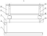
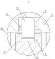
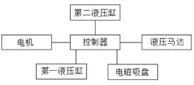
Fig. 1 is a schematic structural diagram of the present invention; FIG. 2 is an enlarged view of the view from the direction A of FIG. 1; FIG. 3 is an enlarged view of section I of FIG. 1; FIG. 4 is an enlarged view of a portion II of FIG. 1; fig. 5 is a block diagram of the circuit module of the present invention.
Detailed Description
In order to make the objects, technical solutions and advantages of the embodiments of the present invention clearer, the embodiments of the present invention will be clearly and completely described below with reference to the accompanying drawings in the embodiments of the present invention, and it is obvious that the described embodiments are some, but not all, embodiments of the present invention. Based on the embodiments in the present invention, all other embodiments obtained by a person skilled in the art without creative efforts belong to the protection scope of the present invention.
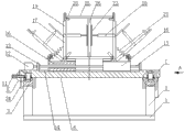
An automatic assembling device for medium and heavy welding H-shaped steel production comprises a base 1, wherein stand columns 2 are fixedly installed on four corners of the top surface of the base 1 respectively, the stand columns 2 which are opposite from each other in the front and back are fixedly connected through connecting rods 3, grooves 4 are formed in the top surfaces of the connecting rods 3 respectively, racks 5 are fixedly installed on the bottom surfaces of the grooves 4, a plurality of strip-shaped plates 6 are arranged above the base 1, tooth grooves 7 are formed in two sides of the bottom surfaces of the strip-shaped plates 6 respectively, rotating shafts 8 are installed in the tooth grooves 7 respectively through bearings, gears 9 are fixedly installed on the peripheries of the rotating shafts 8 respectively, the gears 9 are meshed with the corresponding racks 5, through holes 10 are formed in one sides of the strip-shaped plates 6, the through holes 10 are communicated with the tooth grooves 7 on the same side, the central lines of the through holes 10 are connected with the central lines of the rotating shafts 8, a controller, the motor 11 is a positive and negative rotation motor, the motor 11 is connected with a power supply and a controller circuit, an output shaft of the motor 11 passes through a through hole 10 and then is fixedly connected with the outer end of a rotating shaft 8, two sides of the top surface of the strip-shaped plate 6 are respectively and fixedly provided with a connecting plate 12, a screw 13 is horizontally arranged between the two connecting plates 12, two ends of the screw 13 are respectively connected with inner side bearings of the corresponding connecting plates 12, the thread directions of two sides of the central line of the screw 13 are opposite, the top surface of the strip-shaped plate 6 is provided with a sliding groove 14, the sliding groove 14 is positioned between the two connecting plates 12, two sides of the sliding groove 14 are respectively and movably provided with a sliding block 15, the surface of the sliding block 15 is in contact fit with the inner wall of the sliding groove 14, one side of the sliding block 15 is respectively provided with a screw hole 16, the screw 13 passes through the, the first L-shaped plates 17 are oppositely arranged, the upper parts of the inner sides of the vertical plates of the first L-shaped plates 17 are respectively fixedly provided with a first hydraulic cylinder 18, the hydraulic control system of the first hydraulic cylinder 18 is connected with a controller circuit, the top surfaces of the first L-shaped plates 17 are respectively fixedly provided with a second hydraulic cylinder 19, the hydraulic control system of the second hydraulic cylinder 19 is connected with the controller circuit, the top parts of the inner sides of hydraulic rods of the second hydraulic cylinders 19 are respectively fixedly provided with a second L-shaped plate 20, the inner sides of the vertical plates of the second L-shaped plates 20 are coplanar with the inner sides of the vertical plates 17 of the first L-shaped plates 17, so that wing plates above the vertical plates can be arranged between the second L-shaped plates 20, the outer sides of the first L-shaped plates 17 are connected with corresponding sliding blocks 15 through a plurality of tension springs 21, one ends of the tension springs 21 are fixedly connected with the upper parts of the outer sides of the first L-, The sum of the gravity of the second hydraulic cylinder 19, the first L-shaped plate 17, the second L-shaped plate 20 and the push plate 23, and one end of the screw 13 is fixedly connected with the power device. The utility model is arranged below a welding device when in use, the welding device is the prior art, the concrete structure and the working process are not described in detail, for example, a five-degree-of-freedom welding and cutting robot with Chinese patent No. CN201510434953.3, a plurality of welding devices can be respectively arranged on two sides of the utility model, when the H-shaped steel is not assembled and the wing plate 25 is not contacted with the first L-shaped plate 17, the first L-shaped plate 17 is in an outward inclined state as shown by dotted lines in figure 1, the motor 11, the hydraulic motor 22, the first hydraulic cylinder 18 and the second hydraulic cylinder 19 do not work, a user firstly hoists one wing plate 25 above the strip-shaped plate 6 horizontally by a hoisting device such as a portal frame, the wing plate 25 is slowly placed between the first L-shaped plates 17, when the bottom surface of the wing plate 25 is contacted with the horizontal plate of the first L-shaped plate 17, the wing plate 25 is continuously placed, the wing plate 25 presses the first L-shaped plate 17 downwards, the first L-shaped plate 17 is turned inwards, when the vertical plate of the first L-shaped plate 17 is perpendicular to the slide block 15, as shown in fig. 1, the bottom surface of the wing plate 25 is in contact fit with the top surface of the first L-shaped plate 17, two sides of the wing plate 25 are in contact fit with the inner side of the corresponding first L-shaped plate 17 respectively, the web plate 26 is vertically hung on the top surface of the wing plate 25 through a hoisting device, the hydraulic rod of the first hydraulic cylinder 18 is extended simultaneously through a controller during hoisting, the hydraulic rod of the first hydraulic cylinder 18 is drawn towards the middle, the push plate 23 is in contact fit with one side corresponding to the web plate 26, the web plate 26 is adjusted to the middle position of the wing plate 25 and clamps and fixes the web plate 26, finally, another wing plate 25 is hung on the top surface of the horizontal plate of the second L-shaped plate 20 through the hoisting device, and the web plate 26, make motor 11 work through the controller, the output shaft of motor 11 drives corresponding pivot 8 to rotate, pivot 8 drives gear 9 to rotate, thereby make the lath 6 move along connecting plate 12, carry the assembled H shaped steel to weld in the welding set, after the welding is accomplished, make the hydraulic stem of first pneumatic cylinder 18 shrink through controlling means, make push pedal 23 separate with web 26, and then transfer finished product H shaped steel to the finished product district through hoist device, when the H shaped steel is moved upwards during hoist and mount, first L template 17 turns over to the outside under the effect of extension spring 21 pulling force, until wing panel 25 and the horizontal plate of first L template 17 under the H shaped steel completely separate, first L template 17 gets back to the initial position under the effect of extension spring 21 pulling force, as shown by the dotted line in figure 1, the utility model discloses at the mutual cooperation between first L template 17, first L template 18 pneumatic cylinder, second L template 20 isotructures, the web 26 and the two wing plates 25 can be directly assembled into an H-shaped structure which can be formed in one step, and then the H-shaped structure is directly welded through the welding device to obtain finished H-shaped steel, so that repeated assembly and welding are avoided, the production flow is reduced, the time is saved, and the production efficiency of the H-shaped steel can be improved. The user can be through the work of controller control hydraulic motor 22, and the screw rod 13 is driven to rotate when hydraulic motor 22 output shaft rotates, makes slider 15 be close to each other or keep away from each other to interval when adjusting the vertical state of first L template 17 can adapt to the pterygoid lamina 25 of different width, and can be through the controller vacant extension or the shrink of the 19 hydraulic stems of second pneumatic cylinder, adjust the height of second L template 20, thereby adapt to the not web of co-altitude, the utility model discloses can adapt to not unidimensional web 26 and pterygoid lamina 25, application range is wide.
Specifically, as shown in fig. 1, the power device according to this embodiment is a hydraulic motor 22, a hydraulic control system of the hydraulic motor 22 is connected to a controller circuit, the hydraulic motor is a low-speed hydraulic motor, such as a YLM radial plunger outer five-star hydraulic motor, an AKS tilt cylinder crankshaft connecting rod type low-speed high-torque hydraulic motor, an AKS inner five-star hydraulic motor and a BM axial flow distribution cycloid hydraulic motor, the hydraulic motor 22 is fixedly installed on one side of the top surface of the strip-shaped plate 6, and an output shaft of the hydraulic motor 22 is fixedly connected to one end of the screw 13. The hydraulic motor is small in size, high in flexibility and convenient to control, a user can rotate the screw 13 through the work of the hydraulic motor 22, the sliding blocks 15 can move along the sliding grooves 14 when the screw 13 rotates, and the moving directions of the two sliding blocks 14 are opposite when the hydraulic motor 21 drives the screw 13 to rotate due to the fact that the thread directions of the two sides of the central line of the screw 13 are opposite, and therefore the user can conveniently adjust the distance between the two sliding blocks 14.
Specifically, as shown in fig. 1, the end portions of the hydraulic rods of the first hydraulic cylinders 18 according to the embodiment are all fixedly provided with push plates 23. The user makes the hydraulic stem of first pneumatic cylinder 18 extend through the controller, makes push pedal 23 respectively with the both sides contact cooperation of web 26, and two push pedal 23 mutually support and can adjust the web 26 to the intermediate position of pterygoid lamina 25 top surface, the phenomenon of dislocation appears when avoiding web 26 and pterygoid lamina 25 to weld.
Further, as shown in fig. 1, a rubber pad is fixedly mounted on the top surface of the slider 15 according to the embodiment. This structural design can play the cushioning effect, and when avoiding the upset of first L template 17, the bottom surface of first L template 17 horizontal plate takes place to collide with the top surface of corresponding slider 14, protects first L template 17 and slider 14.
Further, as shown in fig. 1, the sliding groove 14 according to the present embodiment is coated with a lubricant. This structural design can reduce the frictional force between spout 14 and the slider 15, makes slider 15 remove in spout 14 more easily, avoids appearing slider 15 and blocks, improves the utility model discloses a reliability.
Furthermore, as shown in fig. 1, U-shaped frames 24 are respectively and fixedly installed on two sides of the bottom surface of the strip-shaped plate 6, two ends of each U-shaped frame 24 are respectively and fixedly connected with the bottom surface of the strip-shaped plate 6, and the U-shaped frames 24 are respectively sleeved on the peripheries of the corresponding connecting rods 3. This structural design can restrict the removal of the Z axle direction of strip shaped plate 6, prevents that strip shaped plate 6 from taking place to topple, improves the utility model discloses a security.
Finally, it should be noted that: the above embodiments are only used to illustrate the technical solution of the present invention, and not to limit it; although the present invention has been described in detail with reference to the foregoing embodiments, it should be understood by those skilled in the art that: the technical solutions described in the foregoing embodiments may still be modified, or some technical features may be equivalently replaced; such modifications and substitutions do not depart from the spirit and scope of the present invention in its corresponding aspects.
Claims (6)
1. The utility model provides a well heavy welding H shaped steel production is with automatic assembly device which characterized in that: comprises a base (1), upright columns (2) are respectively and fixedly installed at four corners of the top surface of the base (1), the upright columns (2) which are opposite from each other in the front and back are fixedly connected through a connecting rod (3), grooves (4) are respectively formed in the top surface of the connecting rod (3), racks (5) are respectively and fixedly installed on the bottom surfaces of the grooves (4), a plurality of strip-shaped plates (6) are arranged above the base (1), tooth grooves (7) are respectively formed in two sides of the bottom surfaces of the strip-shaped plates (6), rotating shafts (8) are respectively installed in the tooth grooves (7) through bearings, gears (9) are respectively and fixedly installed on the peripheries of the rotating shafts (8), the gears (9) are meshed with the corresponding racks (5), through holes (10) are formed in one sides of the strip-shaped plates (6), the through holes (10) are communicated with the tooth grooves (7) on the same side, a controller with a control, an output shaft of a motor (11) penetrates through a through hole (10) and then is fixedly connected with the outer end of a rotating shaft (8), two sides of the top surface of a strip-shaped plate (6) are respectively and fixedly provided with a connecting plate (12), a screw rod (13) is horizontally arranged between the two connecting plates (12), two ends of the screw rod (13) are respectively connected with inner side bearings of the corresponding connecting plates (12), the thread directions of two sides of the central line of the screw rod (13) are opposite, the top surface of the strip-shaped plate (6) is provided with a sliding chute (14), the sliding chute (14) is positioned between the two connecting plates (12), two sides of the sliding chute (14) are respectively and movably provided with a sliding block (15), one side of the sliding block (15) is respectively provided with a screw hole (16), the screw rod (13) penetrates through the screw hole (16) and is in threaded fit with the screw hole, the inner side of the top surface of the sliding block (15) is hinged with a first L, the top surface of first L template (17) is fixed mounting second hydraulic cylinder (19) respectively, and the inboard top of second hydraulic cylinder (19) hydraulic stem all fixed mounting second L template (20), and the outside of first L template (17) is connected through several extension spring (21) with slider (15) that correspond, and the one end and the power device fixed connection of screw rod (13).
2. The automatic assembling device for medium and heavy type welding H-shaped steel production according to claim 1, characterized in that: the power device is a hydraulic motor (22), the hydraulic motor (22) is fixedly installed on one side of the top surface of the strip-shaped plate (6), and an output shaft of the hydraulic motor (22) is fixedly connected with one end of the screw (13).
3. The automatic assembling device for medium and heavy type welding H-shaped steel production according to claim 1, characterized in that: the end parts of the hydraulic rods of the first hydraulic cylinders (18) are fixedly provided with push plates (23).
4. The automatic assembling device for medium and heavy type welding H-shaped steel production according to claim 1, characterized in that: and a rubber pad is fixedly arranged on the top surface of the sliding block (15).
5. The automatic assembling device for medium and heavy type welding H-shaped steel production according to claim 1, characterized in that: lubricating oil is smeared in the sliding groove (14).
6. The automatic assembling device for medium and heavy type welding H-shaped steel production according to claim 1, characterized in that: the bottom surface both sides of bar shaped plate (6) respectively fixed mounting U type frame (24), the both ends of U type frame (24) respectively with the bottom surface fixed connection of bar shaped plate (6), U type frame (24) suit respectively in the periphery of connecting rod (3) that correspond.
Priority Applications (1)
| Application Number | Priority Date | Filing Date | Title |
|---|---|---|---|
| CN201922199016.0U CN211414167U (en) | 2019-12-10 | 2019-12-10 | Automatic assembling device for production of medium-heavy welded H-shaped steel |
Applications Claiming Priority (1)
| Application Number | Priority Date | Filing Date | Title |
|---|---|---|---|
| CN201922199016.0U CN211414167U (en) | 2019-12-10 | 2019-12-10 | Automatic assembling device for production of medium-heavy welded H-shaped steel |
Publications (1)
| Publication Number | Publication Date |
|---|---|
| CN211414167U true CN211414167U (en) | 2020-09-04 |
Family
ID=72247529
Family Applications (1)
| Application Number | Title | Priority Date | Filing Date |
|---|---|---|---|
| CN201922199016.0U Expired - Fee Related CN211414167U (en) | 2019-12-10 | 2019-12-10 | Automatic assembling device for production of medium-heavy welded H-shaped steel |
Country Status (1)
| Country | Link |
|---|---|
| CN (1) | CN211414167U (en) |
Cited By (1)
| Publication number | Priority date | Publication date | Assignee | Title |
|---|---|---|---|---|
| CN112644578A (en) * | 2020-11-10 | 2021-04-13 | 燕山大学 | Condensed physical experiment device |
-
2019
- 2019-12-10 CN CN201922199016.0U patent/CN211414167U/en not_active Expired - Fee Related
Cited By (1)
| Publication number | Priority date | Publication date | Assignee | Title |
|---|---|---|---|---|
| CN112644578A (en) * | 2020-11-10 | 2021-04-13 | 燕山大学 | Condensed physical experiment device |
Similar Documents
| Publication | Publication Date | Title |
|---|---|---|
| CN112355349A (en) | Machining device for multi-station forklift wheels | |
| CN211414167U (en) | Automatic assembling device for production of medium-heavy welded H-shaped steel | |
| CN111941171A (en) | Casting pipe fitting inner wall grinding device | |
| CN111421163A (en) | Main bearing cap boring tool | |
| CN107695685A (en) | Work treatment installation | |
| CN218576559U (en) | Adjustable stair mould roll-over table of assembled | |
| CN203764708U (en) | Three-roller section bending machine for large-size sections | |
| CN115781356A (en) | Automatic clamping jig and method for mobile phone production | |
| CN206445121U (en) | A kind of punching press Intelligent transfer robot provided with elevating function | |
| CN107511532A (en) | Numerical control horizontal circular saw bench feeding device | |
| CN207290028U (en) | A kind of rotatable stage that can precisely lift positioning | |
| CN208542738U (en) | A kind of milling train adjustable rack | |
| CN111711328A (en) | Motor bearing equipment with automatic installation | |
| CN220407165U (en) | Drilling machine tool with range-increasing system | |
| CN111215627A (en) | Intelligent manufacturing device and preparation process for titanium alloy additive | |
| CN105081423A (en) | Combined portable full-hydraulic power feeding milling machine and machining method | |
| CN219004115U (en) | Lifting centering pushing bed | |
| CN220007746U (en) | Stator rotating tool with adjustable width during motor offline | |
| CN215160669U (en) | Intelligent manufacturing assembling equipment | |
| CN211710097U (en) | High steady hydraulic press | |
| CN213379071U (en) | Hydraulic machine for forging automobile part machining die | |
| CN216965940U (en) | High efficiency numerical control system bender | |
| CN219820685U (en) | Double-deck tube core pipe poling equipment | |
| CN218642368U (en) | Secondary lifting shear type lifter | |
| CN214519092U (en) | Numerical control machine tool convenient for adjusting damping angle |
Legal Events
| Date | Code | Title | Description |
|---|---|---|---|
| GR01 | Patent grant | ||
| GR01 | Patent grant | ||
| CF01 | Termination of patent right due to non-payment of annual fee |
Granted publication date: 20200904 Termination date: 20211210 |
|
| CF01 | Termination of patent right due to non-payment of annual fee |