CN211378671U - Be applied to moving of SMT installation line and carry device - Google Patents
Be applied to moving of SMT installation line and carry device Download PDFInfo
- Publication number
- CN211378671U CN211378671U CN202020078868.4U CN202020078868U CN211378671U CN 211378671 U CN211378671 U CN 211378671U CN 202020078868 U CN202020078868 U CN 202020078868U CN 211378671 U CN211378671 U CN 211378671U
- Authority
- CN
- China
- Prior art keywords
- groove
- fixedly mounted
- plate
- mounting
- smt
- Prior art date
- Legal status (The legal status is an assumption and is not a legal conclusion. Google has not performed a legal analysis and makes no representation as to the accuracy of the status listed.)
- Active
Links
Images


Landscapes
- Specific Conveyance Elements (AREA)
Abstract
The utility model discloses a be applied to moving of SMT subsides dress line and carry device relates to SMT subsides dress processing technology field, including roof, first track and second track, the equal fixed mounting in bottom both sides of roof has the support column, the bottom fixed mounting of support column has the mounting panel, the top slidable mounting of roof has the fly leaf, the equal fixed mounting in bottom both sides of fly leaf has the slider, the top fixed mounting of roof has electronic spout, electronic spout sets up to two, first logical groove has been seted up at the top of roof, the bottom fixed mounting of fly leaf has the connecting block. This be applied to move of SMT subsides dress line moves device through setting up first logical groove, electronic spout, slider and connecting block, under the cooperation of electronic spout and slider, removes the product of centre gripping, shifts to the second track on, reaches the purpose that shifts the product to mechanized replacement manual handling reduces manpower and materials, improves production efficiency.
Description
Technical Field
The utility model relates to a SMT pastes dress processing technology field specifically is a be applied to moving of SMT subsides dress line and carry device.
Background
SMT is a fourth-generation electronic assembly technology, and has the advantages of high component installation density, easy automation, high production efficiency and low cost.
At present, the SMT production line needs to transfer products in the production process, but the products are generally transferred in a manual carrying mode in the process of transferring the products, so that manpower and material resources are improved, and the production efficiency is reduced.
SUMMERY OF THE UTILITY MODEL
An object of the utility model is to provide a be applied to moving of SMT subsides dress line and carry device to solve the problem that proposes among the above-mentioned background art.
In order to achieve the above object, the utility model provides a following technical scheme: a transfer device applied to an SMT mounting line comprises a top plate, a first rail and a second rail, wherein support columns are fixedly mounted on two sides of the bottom of the top plate, a mounting plate is fixedly mounted on the bottom of each support column, a movable plate is slidably mounted on the top of the top plate, sliders are fixedly mounted on two sides of the bottom of the movable plate, electric chutes are fixedly mounted on the top of the top plate and are arranged in two numbers, a first through groove is formed in the top of the top plate, a connecting block is fixedly mounted on the bottom of the movable plate, an electric telescopic rod is fixedly mounted on the bottom of the connecting block, a holder is fixedly mounted on the bottom of the electric telescopic rod and comprises a driving box and a fixed clamping plate, a driving motor is fixedly mounted inside the driving box, a telescopic rod is fixedly mounted at the output end of the driving motor, and a movable clamping, the bottom of drive case has seted up the second and has led to the groove, the bottom of activity grip block extends to the outside of drive case.
Preferably, a plurality of mounting holes are formed in the surface of the mounting plate, and the mounting holes are uniformly distributed.
Preferably, the electric sliding groove and the sliding block are arranged correspondingly, and the outer side of the sliding block is connected with the inner wall of the electric sliding groove in a sliding mode.
Preferably, the connecting block and the first through groove are correspondingly arranged, and the outer side of the connecting block is connected with the inner wall of the first through groove in a sliding mode.
Preferably, the top of the driving box is fixedly connected with the bottom of the electric telescopic rod, and the fixed clamping plate is fixedly installed on the left side of the bottom of the driving box.
Preferably, the second through groove is arranged corresponding to the movable clamping plate, and the outer side of the movable clamping plate is connected with the inner wall of the second through groove in a sliding mode.
Preferably, the first rail and the second rail are distributed in parallel, and the clamper is positioned above the first rail and the second rail.
Compared with the prior art, the beneficial effects of the utility model are that:
(1) this be applied to moving of SMT subsides dress line moves device through setting up drive box, fixed grip block, driving motor telescopic link and activity grip block, can shift the product centre gripping on the first track, the convenience to the product.
(2) This be applied to moving of SMT subsides dress line moves device through setting up first logical groove, electronic spout, slider and connecting block, under the cooperation of electronic spout and slider, removes the product of centre gripping, shifts to the second track on, reaches the purpose that shifts the product to mechanized replacement manual handling reduces manpower and materials, improves production efficiency.
Drawings
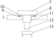
FIG. 1 is a schematic structural view of the present invention;
FIG. 2 is a schematic sectional view of the top plate structure of the present invention;
fig. 3 is a schematic view of the sectional structure of the clamp holder of the present invention.
In the figure: 1. a top plate; 2. a support pillar; 3. mounting a plate; 4. mounting holes; 5. a first track; 6. a second track; 7. a movable plate; 8. a first through groove; 9. an electric chute; 10. a slider; 11. connecting blocks; 12. an electric telescopic rod; 13. a holder; 14. a drive box; 15. fixing the clamping plate; 16. a drive motor; 17. a second through groove; 18. a telescopic rod; 19. a movable clamping plate.
Detailed Description
The technical solutions in the embodiments of the present invention will be described clearly and completely with reference to the accompanying drawings in the embodiments of the present invention, and it is obvious that the described embodiments are only some embodiments of the present invention, not all embodiments. Based on the embodiments in the present invention, all other embodiments obtained by a person skilled in the art without creative work belong to the protection scope of the present invention.
In the description of the present invention, it is to be understood that the terms "center", "longitudinal", "lateral", "length", "width", "thickness", "upper", "lower", "front", "rear", "left", "right", "vertical", "horizontal", "top", "bottom", "inner", "outer", "clockwise", "counterclockwise", "axial", "radial", "circumferential", and the like, indicate the orientation or positional relationship indicated based on the orientation or positional relationship shown in the drawings, and are only for convenience of describing the present invention and simplifying the description, but do not indicate or imply that the device or element referred to must have a particular orientation, be constructed and operated in a particular orientation, and therefore should not be construed as limiting the present invention.
In the present invention, unless otherwise expressly stated or limited, the terms "disposed," "mounted," "connected," "secured," and the like are to be construed broadly, e.g., as meaning either a fixed connection or a removable connection; may be a mechanical connection; may be directly connected or indirectly connected through an intermediate. The specific meaning of the above terms in the present invention can be understood according to specific situations by those skilled in the art.
Furthermore, the terms "first", "second", etc. are used for descriptive purposes only and are not to be construed as indicating or implying relative importance or implicitly indicating the number of technical features indicated. Thus, a feature defined as "first" or "second" may explicitly or implicitly include more than one of the feature. In the description of the present invention, "a plurality" means two or more unless specifically limited otherwise.
Referring to fig. 1-3, the present invention provides a technical solution: a transfer device applied to an SMT mounting line comprises a top plate 1, a first rail 5 and a second rail 6, wherein support columns 2 are fixedly mounted on two sides of the bottom of the top plate 1, a mounting plate 3 is fixedly mounted on the bottom of each support column 2, a plurality of mounting holes 4 are formed in the surface of the mounting plate 3 and are uniformly distributed, a movable plate 7 is slidably mounted on the top of the top plate 1, sliders 10 are fixedly mounted on two sides of the bottom of each movable plate 7, electric chutes 9 are fixedly mounted on the top of the top plate 1, the electric chutes 9 are arranged in two numbers, the electric chutes 9 correspond to the sliders 10, the outer sides of the sliders 10 are slidably connected with the inner walls of the electric chutes 9, a first through groove 8 is formed in the top of the top plate 1, a connecting block 11 is fixedly mounted on the bottom of the movable plate 7, the connecting block 11 corresponds to the first through groove 8, and the outer side of the connecting, through the arrangement of the first through groove 8, the electric sliding groove 9, the sliding block 10 and the connecting block 11, under the cooperation of the electric sliding groove 9 and the sliding block 10, a clamped product is moved and transferred onto the second track 6, the purpose of transferring the product is achieved, manual carrying is replaced by mechanization, manpower and material resources are reduced, production efficiency is improved, the bottom of the connecting block 11 is fixedly provided with an electric telescopic rod 12, the bottom of the electric telescopic rod 12 is fixedly provided with a clamp 13, the first track 5 and the second track 6 are distributed in parallel, the clamp 13 is positioned above the first track 5 and the second track 6, the clamp 13 comprises a driving box 14 and a fixed clamping plate 15, the top of the driving box 14 is fixedly connected with the bottom of the electric telescopic rod 12, the fixed clamping plate 15 is fixedly arranged on the left side of the bottom of the driving box 14, a driving motor 16 is fixedly arranged inside the driving box 14, an output end of the driving motor 16 is fixedly, the right side fixed mounting of telescopic link 18 has movable grip block 19, second through groove 17 has been seted up to drive box 14's bottom, second through groove 17 corresponds the setting with movable grip block 19, the outside of activity grip block 19 and the inner wall sliding connection in second through groove 17, the bottom of activity grip block 19 extends to drive box 14's outside, through setting up drive box 14, fixed grip block 15, 16 telescopic links of driving motor 18 and activity grip block 19, can be with the product centre gripping on the first track 5, the convenience shifts the product.
The working principle is as follows: place the work position with this transfer device, pass mounting hole 4 with the bolt, it is fixed with the workstation to make mounting panel 3, open electric telescopic handle 12, make holder 13 remove downwards, under driving motor 16's effect, make telescopic link 18 drive movable clamping plate 19 and remove, thereby hold the product that is located first track 5, then make electric telescopic handle 12 shrink, under the cooperation of electric sliding groove 9 and slider 10, make the product that grasps remove to second track 6 top, make electric telescopic handle 12 extension again, put into second track 6 with the product, accomplish the transfer to the product.
Although embodiments of the present invention have been shown and described, it will be appreciated by those skilled in the art that changes, modifications, substitutions and alterations can be made in these embodiments without departing from the principles and spirit of the invention, the scope of which is defined in the appended claims and their equivalents.
Claims (7)
1. The utility model provides a be applied to moving of SMT subsides dress line and carry device, includes roof (1), first track (5) and second track (6), its characterized in that: the supporting plate is characterized in that supporting columns (2) are fixedly mounted on two sides of the bottom of the top plate (1), a mounting plate (3) is fixedly mounted on the bottom of the supporting columns (2), a movable plate (7) is slidably mounted on the top of the top plate (1), a slider (10) is fixedly mounted on two sides of the bottom of the movable plate (7), electric sliding grooves (9) are fixedly mounted on the top of the top plate (1), two electric sliding grooves (9) are formed, a first through groove (8) is formed in the top of the top plate (1), a connecting block (11) is fixedly mounted on the bottom of the movable plate (7), an electric telescopic rod (12) is fixedly mounted on the bottom of the connecting block (11), a clamp holder (13) is fixedly mounted on the bottom of the electric telescopic rod (12), the clamp holder (13) comprises a driving box (14) and a fixed clamping plate (15), and a driving, the output fixed mounting of driving motor (16) has telescopic link (18), the right side fixed mounting of telescopic link (18) has movable grip block (19), the second logical groove (17) have been seted up to the bottom of drive case (14), the bottom of activity grip block (19) extends to the outside of drive case (14).
2. A transfer device for an SMT pick and place line according to claim 1, wherein: a plurality of mounting holes (4) have been seted up on the surface of mounting panel (3), and is a plurality of mounting hole (4) are evenly distributed.
3. A transfer device for an SMT pick and place line according to claim 1, wherein: the electric sliding groove (9) and the sliding block (10) are correspondingly arranged, and the outer side of the sliding block (10) is connected with the inner wall of the electric sliding groove (9) in a sliding mode.
4. A transfer device for an SMT pick and place line according to claim 1, wherein: connecting block (11) and first logical groove (8) correspond the setting, the outside of connecting block (11) and the inner wall sliding connection who leads to groove (8) first.
5. A transfer device for an SMT pick and place line according to claim 1, wherein: the top of drive case (14) and the bottom fixed connection of electric telescopic handle (12), fixed grip block (15) fixed mounting is in the bottom left side of drive case (14).
6. A transfer device for an SMT pick and place line according to claim 1, wherein: the second through groove (17) is arranged corresponding to the movable clamping plate (19), and the outer side of the movable clamping plate (19) is connected with the inner wall of the second through groove (17) in a sliding mode.
7. A transfer device for an SMT pick and place line according to claim 1, wherein: the first rail (5) and the second rail (6) are distributed in parallel, and the clamp holders (13) are positioned above the first rail (5) and the second rail (6).
Priority Applications (1)
| Application Number | Priority Date | Filing Date | Title |
|---|---|---|---|
| CN202020078868.4U CN211378671U (en) | 2020-01-15 | 2020-01-15 | Be applied to moving of SMT installation line and carry device |
Applications Claiming Priority (1)
| Application Number | Priority Date | Filing Date | Title |
|---|---|---|---|
| CN202020078868.4U CN211378671U (en) | 2020-01-15 | 2020-01-15 | Be applied to moving of SMT installation line and carry device |
Publications (1)
| Publication Number | Publication Date |
|---|---|
| CN211378671U true CN211378671U (en) | 2020-08-28 |
Family
ID=72155516
Family Applications (1)
| Application Number | Title | Priority Date | Filing Date |
|---|---|---|---|
| CN202020078868.4U Active CN211378671U (en) | 2020-01-15 | 2020-01-15 | Be applied to moving of SMT installation line and carry device |
Country Status (1)
| Country | Link |
|---|---|
| CN (1) | CN211378671U (en) |
Cited By (2)
| Publication number | Priority date | Publication date | Assignee | Title |
|---|---|---|---|---|
| CN112770622A (en) * | 2020-12-22 | 2021-05-07 | 苏州万旭电子元件有限公司 | Efficient transfer device for SMT (surface mount technology) mounting line and using method thereof |
| CN114229467A (en) * | 2021-12-09 | 2022-03-25 | 江苏新光数控技术有限公司 | Operation transport line for marking machine |
-
2020
- 2020-01-15 CN CN202020078868.4U patent/CN211378671U/en active Active
Cited By (3)
| Publication number | Priority date | Publication date | Assignee | Title |
|---|---|---|---|---|
| CN112770622A (en) * | 2020-12-22 | 2021-05-07 | 苏州万旭电子元件有限公司 | Efficient transfer device for SMT (surface mount technology) mounting line and using method thereof |
| CN112770622B (en) * | 2020-12-22 | 2022-04-12 | 苏州万旭电子元件有限公司 | Efficient transfer device for SMT (surface mount technology) mounting line and using method thereof |
| CN114229467A (en) * | 2021-12-09 | 2022-03-25 | 江苏新光数控技术有限公司 | Operation transport line for marking machine |
Similar Documents
| Publication | Publication Date | Title |
|---|---|---|
| CN211378671U (en) | Be applied to moving of SMT installation line and carry device | |
| CN112171554B (en) | Be suitable for centre gripping frock for multiplex spare of fork truck accessory production | |
| CN214705577U (en) | Plate conveying mechanism | |
| CN212918357U (en) | Full-automatic rubber ring sleeving machine | |
| CN218639668U (en) | Get and expect positioning fixture | |
| CN216632940U (en) | PIN welding and clamping fixture for IGBT module | |
| CN211219544U (en) | Automatic assembling equipment for brake disc | |
| CN216326319U (en) | Nut transmission mechanism suitable for automatic assembly equipment of fastener | |
| CN215613352U (en) | Automatic sorting equipment | |
| CN211540665U (en) | Cylinder turning device | |
| CN211569371U (en) | Sensor bearing loading attachment | |
| CN211540066U (en) | Box welding frock | |
| CN211125610U (en) | Automatic wafer loading and unloading device for quartz boat | |
| CN109279335B (en) | Automatic magnetic steel inserting method | |
| CN111451761B (en) | Iron core feeding and assembling system | |
| CN214987114U (en) | Transport board tool with location limit structure | |
| CN212096399U (en) | Automatic material grabbing mechanism | |
| CN217376370U (en) | Synchronous transfer device with multiple clamping mechanisms | |
| CN218261602U (en) | Cylinder unit | |
| CN212217665U (en) | Iron core feeding line body of iron core feeding assembly system | |
| CN219566751U (en) | Gantry type material stacker | |
| CN211841948U (en) | Full-automatic manipulator work or material rest | |
| CN221602319U (en) | Jig tool for processing mobile phone shell | |
| CN215709939U (en) | Snatch unloader | |
| CN219216738U (en) | Clamping and transferring mechanism for integrated circuit lead frame |
Legal Events
| Date | Code | Title | Description |
|---|---|---|---|
| GR01 | Patent grant | ||
| GR01 | Patent grant |