CN211256623U - Horizontal suspension cable steel trestle - Google Patents
Horizontal suspension cable steel trestle Download PDFInfo
- Publication number
- CN211256623U CN211256623U CN201921376156.4U CN201921376156U CN211256623U CN 211256623 U CN211256623 U CN 211256623U CN 201921376156 U CN201921376156 U CN 201921376156U CN 211256623 U CN211256623 U CN 211256623U
- Authority
- CN
- China
- Prior art keywords
- horizontal suspension
- trestle
- suspension cable
- horizontal
- main bridge
- Prior art date
- Legal status (The legal status is an assumption and is not a legal conclusion. Google has not performed a legal analysis and makes no representation as to the accuracy of the status listed.)
- Active
Links
Images

Landscapes
- Bridges Or Land Bridges (AREA)
Abstract
The utility model relates to a horizontal suspension cable steel trestle, which comprises trestle piles arranged at the downstream side of a main bridge pier; and a horizontal suspension cable is arranged between two adjacent main bridge piers and connected with the stacked bridge piles through horizontal suspension rods. The horizontal suspension cable is connected with the upstream side of the main bridge pier. The utility model has the advantages that: the steel trestle is tightened in the horizontal direction by adopting the horizontal suspension cable connected with the main bridge pier, so that the capability of resisting flood impact of the trestle can be obviously enhanced, and the structural cost of the steel trestle is reduced; the horizontal suspension rod is connected with the trestle bridge pile through the lifting lug with the safety pin, so that the main bridge pier can be prevented from being damaged due to overlarge load of the horizontal suspension cable, and the safety of the main bridge pier is ensured.
Description
Technical Field
The utility model belongs to bridge construction field especially relates to a horizontal suspension cable steel landing stage.
Background
In the deep water bridge construction, the underwater foundation construction becomes the key and difficult point of the bridge construction. The steel trestle is used as a transport line for personnel, materials and machinery in the whole bridge construction process, the function is very important in the bridge construction process, and the biggest challenge of the deepwater steel trestle is how to ensure the lateral stability of trestle piles under the action of flowing water pressure. The damage of the steel trestle is generally broken instead of being crushed, so the design of the steel trestle needs to reasonably consider the flowing water pressure of the flow velocity of flood to the trestle pile, and determine the reasonable lateral flowing water pressure resistance of the trestle, the lateral impact resistance of the trestle can be neither too high nor too low, the impact resistance is too high, the economy of the trestle is very low, the impact resistance is too low, the trestle is easy to break down, and the impact resistance of the trestle can be improved and the construction cost of the trestle can be reduced by a proper reinforcing means.
Disclosure of Invention
The utility model aims at providing a technical scheme of horizontal suspension cable steel landing stage improves the ability that the landing stage resisted the flood and assaults to ensure the safety of main bridge pier.
In order to realize the purpose, the technical scheme of the utility model is that: a horizontal suspension cable steel trestle comprises trestle piles arranged on the downstream side of main bridge piers, wherein a plurality of trestle piles are arranged between two adjacent main bridge piers; and a horizontal suspension cable is arranged between two adjacent main bridge piers and connected with the stacked bridge piles through horizontal suspension rods.
Furthermore, the horizontal suspension cables are connected to the upstream side of the pier of the main bridge in order to resist the impact force of water flow on the steel trestle.
Furthermore, in order to stably pull and fix the steel trestle, each trestle pile is connected with the horizontal suspension cable through two horizontal suspension rods.
Furthermore, in order to balance the tension of a plurality of horizontal hanging rods on the horizontal suspension cable, the horizontal hanging rods are connected with the trestle piles through tensioners.
Furthermore, the tensioner adjusts the tension of the hanging rod on the horizontal suspension cable, and the tension of the plurality of horizontal hanging rods enables the horizontal suspension cable between two adjacent main bridge piers to be in a catenary shape.
Furthermore, in order to avoid damaging the main bridge pier when the tension of the horizontal suspension cable is overloaded, the horizontal suspension rod is connected with the trestle pile through a lifting lug, the lifting lug is provided with a safety pin, and the safety pin is a pin shaft which is cut off when the load exceeds a safety limit.
Further, as a more preferred shear pin, the shear pin has a limit load of 20 kN.
Further, a preferable structure of the horizontal suspension cable and the horizontal suspension rod is that the horizontal suspension cable is a steel wire rope with a diameter of 50mm, and the horizontal suspension rod is a steel wire rope with a diameter of 15 mm.
The utility model has the advantages that: after the construction of the drilled pile of the main body bearing platform is completed and before a flood period does not come, the steel trestle is tensioned in the water flow direction by adopting the horizontal suspension cable connected with the main bridge pier, so that the flood impact resistance of the trestle can be obviously enhanced, and the structural cost of the steel trestle is reduced; the horizontal suspension rod is connected with the trestle bridge pile through the lifting lug with the safety pin, so that the main bridge pier can be prevented from being damaged due to overlarge load of the horizontal suspension cable, and the safety of the main bridge pier is ensured.
The present invention will be described in detail with reference to the accompanying drawings and examples.
Drawings
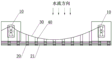
FIG. 1 is a plan view of the present invention;
FIG. 2 is a view of the elevation of the present invention;
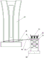
FIG. 3 is an enlarged view of a portion A of FIG. 2;
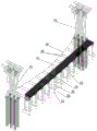
fig. 4 is an overall structure diagram (wire frame diagram) of the present invention.
Detailed Description
Referring to fig. 1, 2 and 3, a horizontal suspension steel trestle comprises trestle piles 20 arranged at the downstream side of main bridge piers 10, wherein a plurality of trestle piles are arranged between two adjacent main bridge piers; and a horizontal suspension cable 30 is arranged between two adjacent main bridge piers and is connected with the stacked bridge piles through horizontal suspension rods 40.
The horizontal suspension cable is connected with the upstream side of the main bridge pier.
And each stack bridge pile is connected with the horizontal suspension cable through the two horizontal suspension rods.
The horizontal boom is connected to the trestle by a tensioner 50.
The tensioner adjusts the tension of the hanger rods on the horizontal suspension cable, and the tension of the horizontal hanger rods enables the horizontal suspension cable between two adjacent main bridge piers to be in a catenary shape.
The horizontal suspender is connected with the trestle pile through a lifting lug 60, the lifting lug is provided with a safety pin 61, and the safety pin is a pin shaft which is cut off when the load exceeds a safety limit.
The limit load of the shear pin is 20 kN.
The horizontal suspension cable is a steel wire rope with the diameter D of 50mm, and the horizontal suspension rod is a steel wire rope with the diameter D of 15 mm.
The first embodiment is as follows:
referring to fig. 1, 2 and 3, the horizontal suspension steel trestle comprises trestle piles 20 arranged on the downstream side of main bridge piers 10, a plurality of trestle piles are arranged between two adjacent main bridge piers, the trestle piles support a trestle bridge floor 21, and the trestle is used for conveying personnel, materials and mechanical equipment to the main bridge in construction.
A horizontal suspension cable 30 is provided between two adjacent main bridge piers, and the horizontal suspension cable connects upstream sides of the main bridge piers (as shown in fig. 1). A steel wire rope (1860 MPa) with the diameter D =50mm is adopted as the horizontal suspension cable. The horizontal suspension cable is fixed at the bottom of the main bridge pier and the top surface of the bearing platform.
The trestle pile comprises bottom sealing concrete 22, a steel pipe column 23 is arranged on the bottom sealing concrete, an I-shaped steel cross beam 24 is arranged at the upper part of the steel pipe column, a longitudinal beam 25 composed of a Bailey beam is arranged on the I-shaped steel cross beam, and a bridge deck 21 adopts an anti-skid steel plate.
The horizontal suspension cables are connected with the trestle bridge piles through horizontal suspension rods 40. The horizontal suspender adopts a steel wire rope with the diameter d =15 mm. Each bridge pile is connected with a horizontal suspension cable through the two horizontal suspension rods. The end of the horizontal boom connected to the trestle pile is provided with a tensioner 50 comprising screws 51 with opposite helical directions at both ends. The tensioner is connected with a lifting lug 60, and the lifting lug is connected with the I-shaped steel cross beam 24 of the trestle pile, so that the connecting structure of the horizontal suspender and the trestle pile is realized. Because a plurality of bridge piles are arranged between two adjacent main bridge piers, a plurality of horizontal suspension rods for connecting the horizontal suspension cables and the bridge piles are arranged. The tensioner has the function of adjusting the tension of the horizontal suspension rods on the horizontal suspension cable, so that the tension of the horizontal suspension cables on the horizontal suspension cable is balanced, and when the tension of the horizontal suspension cables on the horizontal suspension cable is balanced, the horizontal suspension cable between two adjacent main bridge piers can be in a catenary shape.
The lifting lug is provided with a break pin 61, which is a pin that is cut off when the load exceeds a safety limit. In this embodiment, the limit load of the shear pin is 20 kN.
The bottom sealing concrete is equivalent to an enlarged foundation of the trestle, and the instability of the steel trestle at a common water flow speed is prevented; and the longitudinal beam consisting of the tubular pile column and the Bailey beam supports the upper load. The horizontal suspension cables act to resist the pressure of the flowing water during the flood period. The steel trestle is in major structure low reaches, and horizontal span wire anchor is on the pier stud of the drilling pile steel pile casing or major structure that has accomplished, and horizontal span wire adopts the catenary, and horizontal jib adopts adjustable tensioning ware to be connected with the trestle stake, can adjust the pulling force in the work progress, makes the catenary form more close to the catenary. The trestle pile is connected with the tensioner through the lifting lug, the lifting lug is provided with the safety pin, the safety pin carries out destruction calculation according to the maximum tensile force that can bear, and the intensity selects shear strength 0.8 times, makes the horizontal suspender automatically destroy with the connection of trestle pile under too big flood pulling force like this, receives under the effect of too big flowing water pressure at the trestle, prevents that main bridge body structure from taking place to destroy. Not only can the flood resistance of the structure be increased, but also the main structure is not influenced. The steel trestle after increasing the span wire has changed structural style, makes the flood pressure of resisting that the steel trestle can be better, and the tensioning ware can adjust the pulling force of jib, exerts initial pulling force, and the lug plays the effect of protector, destroys automatically when reaching the maximum pulling force of design, plays the guard action to major structure.
Claims (8)
1. A horizontal suspension cable steel trestle comprises trestle piles arranged on the downstream side of main bridge piers, wherein a plurality of trestle piles are arranged between two adjacent main bridge piers; the bridge pier is characterized in that a horizontal suspension cable is arranged between two adjacent main bridge piers and connected with the bridge pier through a horizontal suspension rod.
2. The horizontal suspension cable steel trestle of claim 1, wherein the horizontal suspension cable connects upstream sides of the main bridge piers.
3. The horizontal suspension cable steel trestle of claim 1, wherein each said trestle pile is connected to said horizontal suspension cable by two said horizontal suspenders.
4. The horizontal suspension wire steel trestle of claim 1, wherein the horizontal hanger rods are connected to the trestle piles by tensioners.
5. The horizontal suspension cable steel trestle of claim 4, wherein the tensioners adjust the tension of the suspension rods on the horizontal suspension cable, and the tension of a plurality of horizontal suspension rods makes the horizontal suspension cable between two adjacent main bridge piers in a catenary shape.
6. The horizontal suspension cable steel trestle of claim 1, wherein the horizontal hanger is connected with the trestle pile by a lifting lug, the lifting lug is provided with a safety pin, and the safety pin is a pin which is cut off when the load exceeds a safety limit.
7. A horizontal suspension wire steel trestle according to claim 6, characterised in that the limit load of the shear pin is 20 kN.
8. The horizontal suspension cable steel trestle of claim 1, wherein the horizontal suspension cable is a steel wire rope with a diameter of 50mm, and the horizontal suspension rod is a steel wire rope with a diameter of 15 mm.
Priority Applications (1)
| Application Number | Priority Date | Filing Date | Title |
|---|---|---|---|
| CN201921376156.4U CN211256623U (en) | 2019-08-23 | 2019-08-23 | Horizontal suspension cable steel trestle |
Applications Claiming Priority (1)
| Application Number | Priority Date | Filing Date | Title |
|---|---|---|---|
| CN201921376156.4U CN211256623U (en) | 2019-08-23 | 2019-08-23 | Horizontal suspension cable steel trestle |
Publications (1)
| Publication Number | Publication Date |
|---|---|
| CN211256623U true CN211256623U (en) | 2020-08-14 |
Family
ID=71988694
Family Applications (1)
| Application Number | Title | Priority Date | Filing Date |
|---|---|---|---|
| CN201921376156.4U Active CN211256623U (en) | 2019-08-23 | 2019-08-23 | Horizontal suspension cable steel trestle |
Country Status (1)
| Country | Link |
|---|---|
| CN (1) | CN211256623U (en) |
Cited By (2)
| Publication number | Priority date | Publication date | Assignee | Title |
|---|---|---|---|---|
| CN110424248A (en) * | 2019-08-23 | 2019-11-08 | 中交隧道工程局有限公司 | A kind of horizontal suspension cable steel trestle |
| CN114319069A (en) * | 2022-02-23 | 2022-04-12 | 中国建筑土木建设有限公司 | Large-span steel trestle structure and construction method thereof |
-
2019
- 2019-08-23 CN CN201921376156.4U patent/CN211256623U/en active Active
Cited By (2)
| Publication number | Priority date | Publication date | Assignee | Title |
|---|---|---|---|---|
| CN110424248A (en) * | 2019-08-23 | 2019-11-08 | 中交隧道工程局有限公司 | A kind of horizontal suspension cable steel trestle |
| CN114319069A (en) * | 2022-02-23 | 2022-04-12 | 中国建筑土木建设有限公司 | Large-span steel trestle structure and construction method thereof |
Similar Documents
| Publication | Publication Date | Title |
|---|---|---|
| KR101171039B1 (en) | Partially and fully earth-anchored cable-stayed bridge using main span prestressing appratus and construction method for the same | |
| CN211256623U (en) | Horizontal suspension cable steel trestle | |
| CN207988538U (en) | A kind of overhanging overhanging oblique pull platform of vertical alien invasion | |
| CN106012872B (en) | Continuous rigid frame bridge without dorsal funciculus oblique pull reinforcement system and construction method | |
| KR101800147B1 (en) | Tower crane with safety means | |
| CN107059593A (en) | A kind of interior suspension cable compound section bridge and its construction method | |
| CN109252521B (en) | Equipment for pulling out steel pipe pile in water in limited space under steel beam and construction method thereof | |
| CN109750791A (en) | A kind of assembled large overhanging steel structure | |
| CN111807232A (en) | Cable crane system and hoisting method | |
| CN113565023B (en) | Wind-resistant suspension bridge | |
| CN102926388A (en) | Earth moving device and method for deep foundation pit excavation | |
| CN111139726B (en) | Air bag type floating bridge reinforced by rope | |
| CN204252839U (en) | The spliced crownblock beam of a kind of level | |
| CN212559207U (en) | Bridge floor crane | |
| CN214423122U (en) | Combined type suspender structure of tied-rod arch bridge | |
| CN209816677U (en) | Steel trestle capable of resisting strong water flow impact | |
| CN203188109U (en) | Multi-span ground anchor type suspension bridge | |
| CN204530507U (en) | Long span steel-concrete composite beam cable-stayed bridge limit steel case anchoring temporarily system | |
| CN108867548B (en) | Construction platform and construction platform erection method for on-site watering high pile wharf | |
| CN206752288U (en) | A kind of interior suspension cable compound section bridge | |
| CN208668276U (en) | A kind of Analysis of Suspension Bridges ' Anchorage ground | |
| CN105735155A (en) | Bridge mid-span droop reinforcing device and construction method thereof | |
| CN113529579A (en) | Cableway transfer device based on circulation type steel wire rope catenary structure | |
| CN113445513A (en) | Soil nail anchor cable structure | |
| CN207714165U (en) | A kind of steel structure bridge bracing means |
Legal Events
| Date | Code | Title | Description |
|---|---|---|---|
| GR01 | Patent grant | ||
| GR01 | Patent grant |