CN211218670U - Full-automatic rotating disc type mold casting production equipment - Google Patents
Full-automatic rotating disc type mold casting production equipment Download PDFInfo
- Publication number
- CN211218670U CN211218670U CN201920839123.2U CN201920839123U CN211218670U CN 211218670 U CN211218670 U CN 211218670U CN 201920839123 U CN201920839123 U CN 201920839123U CN 211218670 U CN211218670 U CN 211218670U
- Authority
- CN
- China
- Prior art keywords
- station
- casting
- automatic
- full
- mold
- Prior art date
- Legal status (The legal status is an assumption and is not a legal conclusion. Google has not performed a legal analysis and makes no representation as to the accuracy of the status listed.)
- Active
Links
Images


Landscapes
- Casting Devices For Molds (AREA)
Abstract
The utility model discloses a full-automatic carousel formula mould casting production facility, it includes automatic heat preservation formula casting machine, the full-automatic carousel formula casting machine of six stations, the normalizing furnace, the foundry goods conveyer belt, autofilter separation conveying mechanism, through the cooperation of automatic heat preservation formula casting machine and the full-automatic carousel formula casting machine of six stations, realize automatic pouring, the die sinking, the clearance, and realize dividing the material through autofilter separation conveying mechanism, accomplish and get into the normalizing furnace through the conveying of foundry goods conveyer belt after dividing the material and carry out the normalizing, degree of automation is high, operator technical requirement is lower, artifical quantity significantly reduces, the foundry goods quality improves greatly. This utility model is used for mechanical casting technical equipment field.
Description
Technical Field
The utility model relates to a mechanical casting technical equipment field especially relates to a full-automatic carousel formula mould casting production facility.
Background
The existing metal mold casting production line is mostly a manual casting line arranged in a straight line manner. The existing metal mold casting production line has low automation degree, large requirement on the number of workers and large occupied area, so that the heat loss is large during the transfer of molten iron and the quality of castings is unstable; and the existing metal mold casting production line equipment has high operating technical requirements. With the increase of competition pressure of the industry and the tightening of national environmental protection policies. Upgrading the existing production line, production equipment and production process, and improving the competitiveness of the enterprise is the only way for the survival of the enterprise.
The casting machines in the prior art are all common molten iron casting ladles, the molten iron casting ladles do not have the function of heat active compensation, and the temperature of molten iron can be reduced along with the lapse of casting time to cause the deterioration of fluidity and the change of metallographic phase, so the continuous casting machine is not suitable for automatic continuous casting; the existing mold casting production lines are all arranged in a horizontal line, and a plurality of sets of molds are simultaneously cast by most workers, so that automation cannot be realized; in the existing die casting production process, the temperature of a cast after the die is opened is lower than 500 ℃, and meanwhile, the internal metallographic structure does not completely meet the requirements, such as low hardness, poor wear resistance and more metallographic detection ferrite. In order to make the internal structure of the casting meet the standard and improve the hardness, the casting is subjected to normalizing treatment. At the moment, the temperature of the casting is low, more fuel is needed when the temperature in the furnace reaches about 850-950 degrees (the metallographic structure transformation temperature), so the cost is higher, and more waste gas is generated.
SUMMERY OF THE UTILITY MODEL
An object of the utility model is to provide a degree of automation is high, effectual full-automatic carousel formula mould casting production facility.
The utility model adopts the technical proposal that: a full-automatic rotating disc type mould casting production device comprises an automatic heat preservation type casting machine, a six-station full-automatic rotating disc type casting machine, a normalizing furnace, a casting conveying belt and an automatic screening and separating conveying mechanism; the automatic heat preservation type casting machine comprises a casting machine body and a heating casting ladle arranged on the casting machine body; the six-station full-automatic rotating disc type casting machine comprises a base and a rotating table arranged on the base, wherein a rotary driving motor for driving the rotating table to rotate is arranged on the base, a hydraulic station and a rotary electromechanical signal connector are arranged at the middle position of the rotating table, a pouring station I, a cooling station II, a workpiece taking station III, a sprue cleaning station IV, a blowing cleaning station V and a smoke burning station VI are arranged on the rotating table, the six stations are sequentially arranged along the rotating direction of the rotating table, mold mounting positions for mounting molds are arranged on the six stations, and the mold mounting position of the pouring station I is located right below a temperature-increasing casting bag; automatic screening separation conveying mechanism sets up in the below of getting a station III, automatic screening separation conveying mechanism is including runner separation conveyer belt, foundry goods separation conveyer belt, the rising head conveyer belt that sets up in proper order layering interval, runner separation conveyer belt is located the top, it installs the foundry goods conveyer belt to connect between foundry goods separation conveyer belt and the normalizing furnace.
Further conduct the utility model discloses technical scheme's improvement, it includes fire prevention thermal-insulated structure layer and protective cover to heat the casting package, be provided with the recess that holds the molten metal in the middle of the fire prevention thermal-insulated structure layer, the protective cover is installed on the top of fire prevention thermal-insulated structure layer, be provided with intermediate frequency coil in the fire prevention thermal-insulated structure layer, the protective cover has set up temperature sensor, the bottom of fire prevention thermal-insulated structure layer is provided with waters the export with the communicating molten metal of recess, install the molten metal outflow control carbon-point of vertical movement control molten metal outflow on the protective cover, the molten metal outflow control carbon-point bottom stretches into the molten metal and waters the export.
Further conduct the utility model discloses technical scheme's improvement, install smoke and dust protection casing structure directly over the full-automatic carousel formula casting machine of six stations, smoke and dust protection casing structure includes the stand of six vertical installations, six the stand is installed respectively in the outside of six stations, six the stand top is passed through the crossbeam and is connected formation main part support, install the protection casing on the main part support, six all install camera equipment on the stand, still including the control center of the work of the full-automatic carousel formula mould casting production facility of control, each camera equipment is connected to control center.
Further as an improvement of the technical proposal of the utility model, a sprue cup cleaning mechanism and a first vertical mounting rack for mounting the sprue cup cleaning mechanism are arranged right above the die mounting position of the sprue cleaning station IV, the first vertical mounting frame is fixedly arranged on the cross beam, the pouring cup cleaning mechanism comprises a first stroke-adjustable lifting cylinder arranged at the bottom of the first vertical mounting frame, the first stroke-adjustable lifting cylinder comprises a first cylinder slide bar capable of sliding up and down, a first motor mounting plate is mounted at the bottom end of the first cylinder slide bar, two sides of the bottom end of the first motor mounting plate are provided with steel wire brushes for cleaning the die after die opening and blanking, a wire brush driving motor for driving the wire brush is arranged on two sides of the top end of the first motor mounting plate, and a foreign matter collecting guide groove is arranged right below the die mounting position of the sprue cleaning station IV.
Further conduct the utility model discloses technical scheme's improvement, be provided with the perpendicular mounting bracket of second that the clearance mechanism of blowing and the installation of blowing was blown directly over the die holding position of blowing clearance position V, the perpendicular mounting bracket installation of second is fixed on the crossbeam, the clearance mechanism of blowing is including installing the adjustable stroke lift cylinder of second in the perpendicular mounting bracket bottom of second, the adjustable stroke lift cylinder of second includes gliding second cylinder slide bar from top to bottom, the mouth tapping board of blowing is installed to the bottom of second cylinder slide bar, be provided with a plurality of mouths of blowing that are used for clearing up the metal powder on the mouth tapping board of blowing, the mouth tapping board of blowing is connected main air inlet pipeline, be provided with the foreign matter and receive the basin under the die holding position of blowing clearance position V.
Further as an improvement of the technical scheme of the utility model, a third vertical mounting rack for a cigarette burning mechanism and a third vertical mounting rack for mounting the cigarette burning mechanism are arranged right above the mold mounting position of the cigarette burning station VI, the third vertical mounting rack is fixedly mounted on the beam, the cigarette burning mechanism comprises a second motor mounting plate, one end of the second motor mounting plate can move up and down along the third vertical mounting rack, the second motor mounting plate is provided with a driving motor for driving the second motor mounting plate to move up and down and a driving motor for left and right movement, the bottom of the second motor mounting plate is provided with two vertical acetylene main air inlet pipes, the bottom of the two acetylene main air inlet pipes is welded with an air blowing port adapter pipe perpendicular to the acetylene main air inlet pipes, the driving motor for left and right movement drives the two acetylene main left and right movement air inlet pipes respectively, the two sides of the air blowing port adapter pipe are, and a foreign matter receiving basin is arranged right below the die mounting position of the cigarette burning station VI.
Further conduct the utility model discloses technical scheme's improvement, the pouring station I outside is equipped with exhaust mechanism, the unsteady mold core threaded connection of mould has the external extension pipe of mold core, exhaust mechanism is including fixing the first cylinder mount pad on the workstation in the revolving stage outside and installing the first reciprocating cylinder on first cylinder mount pad, the output threaded connection of first reciprocating cylinder has the first air duct of connecing soon, first connect the air duct output and the external extension pipe intercommunication of mold core soon, be provided with evacuation equipment pipe on the first air duct of connecing soon.
Further conduct the utility model discloses technical scheme's improvement, the cooling station II outside is equipped with cooling mechanism, cooling mechanism is including fixing the second cylinder mount pad on revolving stage outside workstation and installing the second reciprocating cylinder on the second cylinder mount pad, the output threaded connection of the second reciprocating cylinder has the second to connect the air duct soon, the second connects air duct output and the external extension pipe intercommunication of mold core soon, the second connects the cold air duct that is provided with on the air duct soon and lets in air conditioning, can let in inside cooling mold core and work piece with high-pressure gas or nitrogen gas through the cold air duct.
Further conduct the utility model discloses technical scheme's improvement, it is latticed conveyer belt to runner the sorting conveyer belt, the net size of runner the sorting conveyer belt is less than the size of watering, is greater than foundry goods size and rising head size, the foundry goods sorting conveyer belt is latticed conveyer belt, the net size of foundry goods sorting conveyer belt is less than the foundry goods size, is greater than the rising head size, the rising head conveyer belt is close check chain conveyer belt, the foundry goods sorting conveyer belt is connected with foundry goods direction chute, foundry goods direction chute output is located the foundry goods conveyer belt, it is provided with the collecting box of watering under the outside of sorting conveyer belt to runner, be provided with the rising head collecting box under the outside of rising head conveyer belt.
Further as the utility model discloses technical scheme's improvement, the frame mounting panel that relative interval set up is installed to the die holding position, two install the guide pillar between the frame mounting panel, install movable mould mounting panel and cover half mounting panel on the guide pillar, the movable mould is installed to the inboard of movable mould mounting panel, the cover half mounting panel is fixed with a frame mounting panel, the cover half is installed to the inboard of cover half mounting panel, all be provided with condenser tube on movable mould and the cover half, be provided with the movable mould kicking roll on the movable mould mounting panel, cover half one side is provided with the thermocouple that detects mould core temperature, the thermocouple passes the cover half mounting panel and pegs graft in the mounting hole of cover half.
The utility model has the advantages that: this full-automatic carousel formula mould casting production facility, it includes automatic heat preservation formula casting machine, six station full-automatic carousel formula casting machines, normalizing furnace, the foundry goods conveyer belt, autofilter separation conveying mechanism, through automatic heat preservation formula casting machine and six station full-automatic carousel formula casting machine cooperations, realize automatic pouring, the die sinking, the clearance, and realize dividing the material through autofilter separation conveying mechanism, accomplish to divide the material after, pass through the conveying of foundry goods conveyer belt and get into normalizing furnace and carry out the normalizing, degree of automation is high, operator technical requirement is lower, artifical quantity significantly reduces, the foundry goods quality improves greatly.
Drawings
In order to more clearly illustrate the technical solutions of the embodiments of the present invention, the drawings used in the description of the embodiments will be briefly introduced below, and it is obvious that the drawings in the following description are only some embodiments of the present invention, and it is obvious for those skilled in the art that other drawings can be obtained according to these drawings without creative efforts.
Fig. 1 is a schematic view of the overall structure of the embodiment of the present invention;
FIG. 2 is a schematic view of a six-station fully automatic rotating disc type casting machine according to the embodiment of the present invention;
FIG. 3 is an overall view of an automatic heat-preservation type casting machine according to an embodiment of the present invention;
FIG. 4 is a schematic structural view of a temperature-increasing ladle according to an embodiment of the present invention;
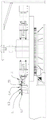
FIG. 5 is a front view of a six-station full-automatic rotating disc type casting machine according to the embodiment of the present invention;
FIG. 6 is a top view of the six-station full-automatic rotating disc type casting machine of the embodiment of the present invention;
FIG. 7 is a perspective view of a six-station full-automatic rotating-disc casting machine according to an embodiment of the present invention;
FIG. 8 is a side view of a casting station according to an embodiment of the present invention;
figure 9 is a side view of a cooling station according to an embodiment of the present invention;
FIG. 10 is a top view of a pouring cup cleaning mechanism according to an embodiment of the present invention;
fig. 11 is an elevation view of the pouring cup cleaning mechanism according to the embodiment of the present invention in fig. 10;
FIG. 12 is a top view of the air blowing cleaning mechanism according to the embodiment of the present invention;
FIG. 13 is an elevation view of the air blowing cleaning mechanism of the embodiment of the present invention in FIG. 12;
FIG. 14 is an enlarged view of the tapping plate of the blowing port of the embodiment of the present invention;
FIG. 15 is a top view of a cigarette burning mechanism according to an embodiment of the present invention;
fig. 16 is an elevation view of the cigarette burning mechanism of the embodiment of the present invention fig. 15;
fig. 17 is a side view of the embodiment of the present invention fig. 16;
fig. 18 is a top view of the embodiment of the present invention fig. 16;
fig. 19 is a schematic view of an automatic screening, separating and conveying mechanism according to an embodiment of the present invention;
fig. 20 is a top view of the embodiment of the present invention fig. 19;
FIG. 21 is a schematic structural view of a mold mounting position according to an embodiment of the present invention;
fig. 22 is a top view of the embodiment of the present invention fig. 21;
fig. 23 is an installation schematic view of the smoke exhaust protective cover structure of the embodiment of the present invention.
Detailed Description
Referring to fig. 1 to 23, the utility model discloses a full-automatic carousel formula mould casting production facility, it includes automatic heat preservation formula casting machine 1, six station full-automatic carousel formula casting machines 2, normalizing furnace 3, foundry goods conveyer belt 31, autofilter separation conveying mechanism 4.
The automatic heat preservation type casting machine 1 comprises a casting machine body 11 and a heating casting ladle 12 arranged on the casting machine body 11. As the casting machines in the prior art are all common casting ladles and do not have the function of heat active compensation, the temperature of molten metal can be reduced along with the passage of time to cause the deterioration of fluidity and the change of metallographic phase, so that the casting machines are not suitable for automatic continuous casting, and the structure of the casting ladles is improved. Specifically, temperature-increasing casting package 12 includes fire prevention thermal-insulated structure layer 121 and protective cover 122, be provided with the recess 123 that holds the molten metal in the middle of the fire prevention thermal-insulated structure layer 121, protective cover 122 installs the top at fire prevention thermal-insulated structure layer 121, be provided with intermediate frequency coil 124 in the fire prevention thermal-insulated structure layer 121, the last temperature sensor 125 that has set up of protective cover 122, the bottom of fire prevention thermal-insulated structure layer 121 is provided with the communicating molten metal pouring outlet 126 with recess 123, install the molten metal outflow control carbon-point 127 that moves the control molten metal outflow on the protective cover 122, molten metal outflow control carbon-point 127 bottom stretches into molten metal pouring outlet 126. In this embodiment, the molten metal is molten iron, and this kind of casting package 12 that heats utilizes the principle of smelting the intermediate frequency furnace, has set up intermediate frequency coil 124 in fire prevention thermal-insulated structural layer 121, and intermediate frequency coil 124 selects to be the copper coil, has set up the temperature-sensing ware simultaneously on the safety cover, through artifical required molten iron temperature that sets up, when realizing that the molten iron temperature reduces, intermediate frequency coil 124 ohmic heating, when the molten iron temperature satisfies the temperature requirement, intermediate frequency coil 124 outage cancellation heating.
Six full-automatic carousel formula casting machines 2 of station include base 21 and install the revolving stage 22 on base 21, install drive revolving stage 22 pivoted rotary drive motor 23 on the base 21, the intermediate position of revolving stage 22 is provided with hydraulic pressure station 24 and rotatory electromechanical signal connector 25, it totally six stations to be provided with pouring station I, cooling station II, get a station III, clearance runner station IV, the clearance station V of blowing, burns cigarette station VI on the revolving stage 22, pouring station I, cooling station II, get a station III, clearance runner station IV, the clearance station V of blowing, burn cigarette station VI and set gradually along revolving stage 22 rotation direction, six all be provided with the mould installation position 221 of installation mould on the station, pouring station I's mould installation position 221 is located and heats casting package 12 under. The rotary electromechanical signal connector 25 ensures that the electrical signals at the six stations and the electrical signals at the rotary machine are not influenced by rotation, and is preferably a wire slip ring. The hydraulic station 24, the hydraulic pressure of the rotatable machine and the cooling water connector ensure that the continuous supply of the oil pressure and the cooling water of the six stations is not interrupted. The mold mounting position 221 can be respectively connected with a mold temperature detection couple, cooling water and a high-pressure oil circuit, and is not influenced by the continuous rotation of the rotary table 22, a casting falling hole is formed in the workpiece taking station III, and a slag falling hole is formed in the sprue cleaning station IV. And is also connected with an external circulating water system.
Automatic screening separation conveying mechanism 4 sets up in the below of getting a station III, automatic screening separation conveying mechanism 4 is including runner separation conveyer belt 41, foundry goods separation conveyer belt 42, the rising head conveyer belt 43 that sets up in proper order layering interval, runner separation conveyer belt 41 is located topmost, be connected between foundry goods separation conveyer belt 42 and normalizing furnace 3 and install foundry goods conveyer belt 31.
This full-automatic carousel formula mould casting production facility, it includes automatic heat preservation formula casting machine 1, six station full-automatic carousel formula casting machines 2, normalizing furnace 3, foundry goods conveyer belt 31, autofilter separation conveying mechanism 4, through automatic heat preservation formula casting machine 1 with six station full-automatic carousel formula casting machines 2 cooperation, realize automatic pouring, the die sinking, the clearance, and realize dividing the material through autofilter separation conveying mechanism 4, accomplish and divide the material after, pass through foundry goods conveyer belt 31 conveying and get into normalizing furnace 3 and carry out the normalizing, degree of automation is high, operator technical requirement is lower, the manual work quantity significantly reduces, the foundry goods quality improves greatly.
As the utility model discloses preferred embodiment, in order to reduce to minimum with the middle dust, the cigarette emission of casting production in-process, this six station full-automatic carousel formula casting machine 2 top special design one by hexagonal support smoke and dust protection casing structure 26. A smoke and dust extraction protective cover structure 26 is installed right above the six-station full-automatic rotating disc type casting machine 2, the smoke and dust extraction protective cover structure 26 comprises six upright posts 261 which are vertically installed, the six upright posts 261 are respectively installed on the outer sides of the six stations, the tops of the six upright posts 261 are connected through a cross beam 262 to form a main body support 263, and a protective cover 264 is installed on the main body support 263. Under the action of the fan, the gas containing smoke dust enters the dust remover gas box from the air inlet on the upper part of the dust remover, dust particles with small density and fine particle size enter the dust filtering chamber, and then are adsorbed on the outer surface of the filter material through the combined effects of Brown diffusion, sieving and the like, and the filtered clean gas enters the gas purifying chamber through the filter cylinder and is collected to the air outlet for exhaust through the fan by the exhaust pipe. Six all install camera equipment on the stand 261, still include the control center 27 of control full-automatic carousel formula mould casting production facility work, each camera equipment is connected to control center 27. The six-station camera equipment forms a six-station real-time video monitoring system, the real-time situation of the six-station full-automatic rotating disc type casting machine 2 can be found in time, video signals are uniformly transmitted to the control center 27, and when problems are found, the control center 27 suspends casting and manually processes the problem points.
As the utility model discloses preferred embodiment, at clearance runner station IV, the mould has accomplished the die sinking blanking this moment, because the pouring basin forms tiny iron fillings and adhesion in the pouring basin easily in molten iron casting process, if not clear away can be when the next casting molten iron inflow product die cavity, form and press from both sides the sediment, so be provided with a pouring basin clearance mechanism 7 that can move about from top to bottom on this station. A sprue cup cleaning mechanism 7 and a first vertical mounting frame 71 for mounting the sprue cup cleaning mechanism 7 are arranged right above a mould mounting position 221 of the sprue cleaning station IV, an air pipe and an electric wire are connected to an external controller along the frame, the first vertical mounting frame 71 does not rotate along with the rotary table 22, the vertical mounting frame 71, the first vertical mounting bracket 71 is fixedly arranged on the cross beam 262, the pouring cup cleaning mechanism 7 comprises a first adjustable stroke lifting cylinder 72 arranged at the bottom of the first vertical mounting bracket 71, the first adjustable stroke lift cylinder 72 includes a first cylinder slide 73 that slides up and down, first motor mounting panel 74 is installed to first cylinder slide bar 73 bottom, the steel wire brush 75 that is used for clearing up the mould after the die sinking blanking is installed to the bottom both sides of first motor mounting panel 74, and the installation interval of two steel wire brushes 75 is adjusted the mould and is opened the interval of back both sides pouring basin. The wire brush driving motor 76 for driving the wire brush 75 is installed on two sides of the top end of the first motor installation plate 74, a foreign matter collection guide groove is arranged right below the die installation position 221 of the cleaning pouring gate station IV, and iron slag brushed down is guided into a riser collection box at the bottom through the groove. When the mold reaches the sprue cleaning station IV, the first stroke-adjustable lifting cylinder 72 descends to a fixed position, and simultaneously the wire brush driving motor 76 is started to move back and forth once to clean foreign matters such as iron slag in the sprue cup.
As the utility model discloses preferred embodiment, because after clearance runner station IV brushed the pouring basin, there was some iron powder to produce, the adhesion was in pouring basin, vertical runner and some horizontal runner, so increased the clearance station V of blowing. A blowing cleaning mechanism 8 and a second vertical mounting rack 81 for mounting the blowing cleaning mechanism 8 are arranged right above the die mounting position 221 of the blowing cleaning station V, the air pipe is connected to an external controller along the second vertical mounting rack 81, the second vertical mounting rack 81 does not rotate along with the rotary table 22, the second vertical mounting rack 81 is fixedly arranged on the cross beam 262, the air blowing cleaning mechanism 8 comprises a second stroke-adjustable lifting cylinder 82 arranged at the bottom of the second vertical mounting rack 81, the second adjustable stroke lift cylinder 82 includes a second cylinder slide 83 that slides up and down, the bottom of the second cylinder slide bar 83 is provided with a gas blowing opening tapping plate 84, the gas blowing opening tapping plate 84 is provided with a plurality of gas blowing openings 85 for cleaning metal powder, the air blowing opening tapping plate 84 is connected with a main air inlet pipeline 86, and a foreign matter receiving basin is arranged right below a mold mounting position 221 of the air blowing cleaning station V. When blowing, a small amount of foreign matters fall off, and the foreign matter receiving basin is cleaned regularly. When the mold reaches the blowing cleaning station V, the second stroke-adjustable lifting cylinder 82 descends to a fixed position, meanwhile, compressed air is started through the electromagnetic valve, the compressed air is blown to the mold from the pouring cup to be vertically poured to a joint position in a one-time reciprocating motion, and when the mold is retracted to the position of the pouring cup from bottom to top, the compressed air is controlled to be closed through the electromagnetic valve. The length of the air blowing opening tapping plate 84 is equal to the total length of the mold, and a plurality of air blowing openings 85 are arranged on the air blowing opening tapping plate 84.
As a preferred embodiment of the present invention, a third vertical mounting frame 91 for installing the smoke burning mechanism 9 and the smoke burning mechanism 9 is disposed right above the mold mounting position 221 of the smoke burning station VI, the third vertical mounting frame 91 is fixedly mounted on the cross beam 262, the smoke burning mechanism 9 includes a second motor mounting plate 92 with one end capable of moving up and down along the third vertical mounting frame 91, the second motor mounting plate 92 is mounted with a vertical movement driving motor 93 for driving the second motor mounting plate 92 to move up and down and a left and right movement driving motor 94, the bottom of the second motor mounting plate 92 is mounted with two vertical acetylene main intake pipes 95, the bottom of the two acetylene main intake pipes 95 is welded with a blowing port adapter pipe 96 perpendicular to the acetylene main intake pipes 95, the left and right movement driving motor 94 respectively drives the two acetylene main intake pipes 95 to move left and right, two sides of the blowing port adapter pipe 96 are provided with ignition ports 97, the two ignition ports 97 are located on the inner wall side of the mold, and a foreign matter receiving basin is arranged right below the mold mounting position 221 of the cigarette burning station VI. The effect of burning cigarette station VI is that it adheres to the effect that the helping hand drawing of patterns is played in the mould internal surface to lead to burning cigarette, burns cigarette mechanism 9 and realizes burning cigarette pipeline lift and left and right translation action by servo motor drive transmission mechanism, accomplishes and burns cigarette process. One pipeline is provided with a positive ignition port 97 and a negative ignition port 97, the left air blowing port and the right air blowing port are respectively connected with a connecting pipe 96, and the four ignition ports 97 point to a movable mould and a fixed mould respectively and are provided with pulse type ignition valves and acetylene and air mixing devices.
Gray cast iron mold: after the mold reaches a smoke burning station, the two ignition ports 97 ignite big fire for combustion, then descend to the sprue cup, the sprue and the cross gate in a three-fork position along the sprue cup and the sprue at a constant speed (adjustable speed) and stop, the two ignition ports 97 in the cross gate three-fork position linearly move leftwards by 250mm at a constant speed (adjustable speed), then return to the cross gate three-fork position, the two ignition ports 97 in the cross gate three-fork position linearly move rightwards by 250mm at a constant speed (adjustable speed), then return to the cross gate three-fork position, then return to the initial position along the sprue cup at a constant speed (adjustable speed), and the flames of the two ignition ports are extinguished.
The nodular cast iron mold comprises: after the mold reaches a smoke burning station, the two ignition ports 97 ignite big fire for combustion, and then descend along the sprue cup and the sprue at a constant speed (with adjustable speed) to three fork positions of the sprue cup, the sprue and the cross gate to stop.
When molten iron is poured into the mold, if gas is trapped in the mold, casting pores and pinholes are poor (the gas source is molten iron decomposition gas such as ammonia gas, water vapor, air and the like which are replaced when the aluminum is excessive), if all the gas is difficult to be effectively discharged by the extrusion force of molten iron flow, the mold cavity forced exhaust mechanism 5 is added while the molten iron is poured into the mold, so that the effect of strengthening exhaust is achieved, and the pore defects are minimized. The exhaust mechanism 5 is fixed at the stop position of the casting station I and is pushed and pulled by a reciprocating cylinder to ensure that an exhaust pipeline does not interfere with the rotating mechanism. As the utility model discloses preferred embodiment, the pouring station I outside is equipped with exhaust mechanism 5, the unsteady mold core threaded connection of mould has the external extension pipe 51 of mold core, exhaust mechanism 5 is including fixing first cylinder mount pad 52 on the workstation in the revolving stage 22 outside and installing first reciprocating cylinder 53 on first cylinder mount pad 52, first reciprocating cylinder 53's output threaded connection has first fast air duct 54 that connects, first fast air duct 54 output and the external extension pipe 51 intercommunication of mold core, be provided with evacuation equipment pipe 55 on the first fast air duct 54 that connects. Specifically, at a pouring station I, the mold is closed to pour molten iron, a mold core of the mold is connected with an external mold core extension pipe 51 through threads, and the other end of the external mold core extension pipe 51 is provided with a convex spherical end which is in butt joint with a first quick-connection air guide pipe 54. One end of the first quick-connection air duct 54 is in threaded connection with the first reciprocating cylinder 53, and the other end of the first quick-connection air duct is provided with an inwards concave conical surface which can be quickly butted with the spherical end of the extension pipe 51 externally connected with the mold core. The convex spherical surface and the concave conical surface are designed, so that the sealing can be effectively realized, and the connection and the separation can be quickly realized. When the first reciprocating cylinder 53 is pushed outwards, the first quick connection air guide pipe 54 is in butt joint with the die core external extension pipe 51, the vacuumizing equipment works, vacuumizing and exhausting are carried out through the vacuumizing equipment pipe 55, 1-3 seconds are delayed after pouring is finished, the first reciprocating cylinder 53 retreats, the first quick connection air guide pipe 54 and the die core external extension pipe 51 are separated from a safety stroke, the rotary table 22 rotates, the second set of die is pushed out again to the pouring station I by the first reciprocating cylinder 53, and the operation is repeated. This is particularly beneficial for annular parts having an internal bore, such as compressor cylinders.
After the casting station I, the molten iron in the mold is cooled, and the shell of the casting is hardened. In order to match with efficient automatic production and the use of a zero draft angle mold, the demolding of an inner hole and a mold core is particularly convenient, and a mold cavity is added at a cooling station II to strengthen a cooling process. It has used for reference pouring into a mould station I's pump drainage mechanism 5, sets up cooling mechanism 6 to with this cooling mechanism 6 at cooling station II installation location, the evacuation equipment that will externally connect is changed into high-pressure cold air and is insufflated equipment simultaneously, for example air compressor machine, high-pressure nitrogen gas, thereby makes the mold core position cool off fast, ensures that foundry goods and mold core effectively demold. As the utility model discloses preferred embodiment, the cooling station II outside is equipped with cooling mechanism 6, cooling mechanism 6 is including fixing second cylinder mount pad 61 on the workstation in the revolving stage 22 outside and installing the second reciprocating cylinder 62 on second cylinder mount pad 61, the output end threaded connection of second reciprocating cylinder 62 has the second to connect air duct 63 soon, the second connects air duct 63 output and the external extension pipe 51 of mold core to communicate soon, the second connects the cold air duct 64 that is provided with the let in air conditioning on the air duct 63 soon. The cooling mechanism 6 is fixed at the stop position of the cooling station II and is pushed and pulled by the second reciprocating cylinder to ensure that the air blowing pipeline is not interfered with the rotating mechanism. At cooling station II, the mould is still closed and continues to cool, sets up the design of the second and connects air duct 61 design indent conical surface soon simultaneously, and indent conical surface and protruding spherical surface cooperation can enough effectively seal, again can be quick-connect and separate. When the second reciprocating cylinder 62 is pushed out, the pipelines are in butt joint, high-pressure cold source gas enters, after the synchronous time with the pouring station I, the cylinder retreats, the butt joint pipeline is released to a safe stroke, the turntable machine rotates, the second reciprocating cylinder 62 is pushed out again from the second set of dies to the cooling station, and the process is repeated.
As the utility model discloses preferred embodiment, during the high temperature die sinking blanking, set up the autofilter separation conveying mechanism 4 that the separation was watered, foundry goods and rising head below getting a station III. Under the use prerequisite of cooperation foundry goods and pouring gate, the automatic disconnected separation mould that pushes up of rising head, when getting a station III die sinking (temperature about 900 ℃), foundry goods, rising head and pouring gate can freely fall on the conveyer belt, for realizing automatic separation this moment, set up the conveyer belt into three laminar structures. From top to bottom, the first layer is formed in sequence: the runner sorting conveyer belt 41 is a grid conveyer belt, the grid size of the runner sorting conveyer belt 41 is smaller than the size of a runner and larger than the size of a casting and the size of a riser, specifically, the conveyer belt is designed to be 200 x 300 rectangular grid by utilizing the characteristic of longer appearance of the runner, so that the casting products and the riser can fall onto the second layer of the conveyer belt, and the runner is separated. A second layer: the casting sorting conveyer belt 42 is a grid-shaped conveyer belt, and the grid size of the casting sorting conveyer belt 42 is smaller than the casting size and larger than the riser size. The casting sorting conveyor 42 takes advantage of the fact that the casting size is larger than the feeder head, which is designed as a 50 x 50 rectangular grid, so that the feeder head can fall onto the third layer of conveyor. And a third layer: and the riser conveying belt 43 is a dense lattice chain conveying belt 43. The casting sorting conveyer belt 42 is connected with a casting guide chute 44, the output end of the casting guide chute 44 is positioned on the casting conveyer belt 31, and the casting guide chute 44 receives the casting on the casting sorting conveyer belt 42 and finally guides the casting to the casting conveyer belt 31 of the normalizing furnace 3. A runner collecting box 45 is arranged right below the outermost side of the runner sorting conveying belt 41, and a riser collecting box 46 is arranged right below the outermost side of the riser conveying belt 43.
As the preferred embodiment of the present invention, the mold mounting position 221 is provided with a base mounting plate 2211 disposed at a relative interval, two guide pillars 2212 are installed between the base mounting plates, a movable mold mounting plate 2213 and a fixed mold mounting plate 2214 are installed on the guide pillars 2212, a movable mold 2215 is installed on the inner side of the movable mold mounting plate 2213, the fixed mold mounting plate 2214 is fixed with the base mounting plate 2211, a fixed mold 2216 is installed on the inner side of the fixed mold mounting plate 2214, cooling water pipes 2217 are both arranged on the movable mold 2215 and the fixed mold 2216, a movable mold top roller 2218 is arranged on the movable mold mounting plate 2213, a thermocouple 2219 for detecting the mold center temperature is arranged on one side of the fixed mold 2216, the thermocouple 2219 passes through the fixed mold mounting plate 2214 and is inserted into the mounting hole of the fixed mold 2216.
The mold temperature directly influences the casting quality, so the mold temperature must be effectively controlled, and meanwhile, the monitoring of the mold temperature can ensure that the casting temperature is kept at about 900 ℃ when the workpiece taking station III opens the mold, thereby providing guarantee for subsequent high-temperature entering into the normalizing furnace. Specifically, in one embodiment, the thermocouple 2219 is an armored thermocouple (reference model: WRNK-191, measurable 0-1000 ℃), a fixed mold 2216 with six stations is loaded, and the thermocouple 2219 penetrates through a fixed mold mounting plate 2214 and is inserted into a thermocouple mounting hole of the fixed mold 2216. The thermocouple 2219 monitors the temperature of the center of the die in real time, because one side of the movable die 2215 is provided with a movable die top roller 2218 as an ejection mechanism, the thermocouple 2219 is arranged on one side of the fixed die 2216, the detected die temperature is fed back to the die cooling water control system in time, the system compares the set value with the feedback value, and when the die temperature is lower than the set value, the cooling water stops; when the mold temperature is higher than the set value, the cooling water is turned on again to reduce the mold temperature, and the information of the six thermocouples 2219 is transmitted to the artificial intelligent temperature controller arranged at the center of the turntable in time and rotates along with the six-station full-automatic rotating disc type casting machine 2.
In the existing metal mold casting production process, the temperature of a casting is lower than 500 ℃ after a mold is opened, and meanwhile, the internal metallographic structure does not completely meet the requirements, such as low hardness, poor wear resistance and more metallographic detection ferrite. In order to make the internal structure of the casting meet the standard and improve the hardness, the casting is subjected to normalizing treatment. At the moment, the temperature of the casting is low, and more fuel needs to be combusted when the temperature in the furnace reaches about 850-950 ℃ (metallographic structure transition temperature), so the cost is high, and more waste gas is generated. Combine above-mentioned problem, the utility model discloses combine casting temperature control, die sinking time control and autofilter separation conveying mechanism 4, proposed and utilized high temperature (900 ℃) die sinking blanking, automatic transport to go into normalizing furnace 3 modes, the temperature is still about 800 + 850 ℃ when realizing that the foundry goods goes into normalizing furnace 3 and carries out the normalizing. The method makes full use of the self waste heat of the casting, reduces the practicability of the fuel in the normalizing furnace 3, reduces the waste and saves the production cost while ensuring the quality of the casting to meet the requirement.
The invention is not limited to the above embodiments, and those skilled in the art can make equivalent modifications or substitutions without departing from the spirit of the invention, and such equivalent modifications or substitutions are included in the scope defined by the claims of the present application.
Claims (10)
1. The utility model provides a full-automatic carousel formula mould casting production facility which characterized in that: comprises an automatic heat preservation type casting machine (1), a six-station full-automatic rotating disc type casting machine (2), a normalizing furnace (3), a casting conveying belt (31) and an automatic screening and separating conveying mechanism (4);
the automatic heat preservation type casting machine (1) comprises a casting machine main body (11) and a temperature-increasing casting ladle (12) arranged on the casting machine main body (11);
the six-station full-automatic rotating disc type casting machine (2) comprises a base (21) and a rotating table (22) arranged on the base (21), a rotary driving motor (23) for driving the rotary table (22) to rotate is arranged on the base (21), a hydraulic station (24) and a rotary electromechanical signal connector (25) are arranged at the middle position of the rotary table (22), the rotary table (22) is provided with six stations of a pouring station I, a cooling station II, a workpiece taking station III, a sprue cleaning station IV, an air blowing cleaning station V and a smoke burning station VI, the casting station I, the cooling station II, the workpiece taking station III, the sprue cleaning station IV, the blowing cleaning station V and the smoke burning station VI are sequentially arranged along the rotation direction of the rotary table (22), mold mounting positions (221) for mounting molds are arranged on the six stations, the die mounting position (221) of the pouring station I is positioned right below the temperature-increasing pouring ladle (12);
automatic screening separation conveying mechanism (4) set up in the below of getting a station II I, automatic screening separation conveying mechanism (4) select separately conveyer belt (41), foundry goods including the runner that sets up in proper order layering interval select separately conveyer belt (42), rising head conveyer belt (43), runner select separately conveyer belt (41) are located topmost, be connected between foundry goods select separately conveyer belt (42) and normalizing furnace (3) and install foundry goods conveyer belt (31).
2. The full-automatic carousel formula mould casting production facility of claim 1, characterized in that: increase temperature casting package (12) are including fire prevention thermal-insulated structure layer (121) and protective cover (122), be provided with recess (123) that hold the molten metal in the middle of fire prevention thermal-insulated structure layer (121), the top at fire prevention thermal-insulated structure layer (121) is installed in protective cover (122), be provided with intermediate frequency coil (124) in fire prevention thermal-insulated structure layer (121), temperature sensor (125) have been set up on protective cover (122), the bottom of fire prevention thermal-insulated structure layer (121) is provided with and waters export (126) with recess (123) communicating molten metal, install molten metal outflow control carbon-rod (127) that move up and down control molten metal outflow volume on protective cover (122), molten metal outflow control carbon-rod (127) bottom stretches into molten metal outlet (126).
3. The full-automatic carousel formula mould casting production facility of claim 1, characterized in that: install smoke and dust protection casing structure (26) directly over six station full-automatic carousel formula casting machines (2), smoke and dust protection casing structure (26) include six vertical installation's stand (261), six install respectively in the outside of six stations stand (261), six the stand (261) top is passed through crossbeam (262) and is connected formation main part support (263), install protection casing (264) on main part support (263), six all install camera equipment on stand (261), still including control center (27) of control full-automatic carousel formula mould casting production facility work, each camera equipment is connected to control center (27).
4. The full-automatic carousel formula mould casting production facility of claim 3, characterized in that: a first vertical mounting frame (71) for cleaning a sprue cup cleaning mechanism (7) and installing the sprue cup cleaning mechanism (7) is arranged right above a die mounting position (221) of the sprue station IV, the first vertical mounting frame (71) is installed and fixed on a cross beam (262), the sprue cup cleaning mechanism (7) comprises a first adjustable stroke lifting cylinder (72) installed at the bottom of the first vertical mounting frame (71), the first adjustable stroke lifting cylinder (72) comprises a first cylinder slide bar (73) capable of sliding up and down, a first motor mounting plate (74) is installed at the bottom end of the first cylinder slide bar (73), steel wire brushes (75) for cleaning dies after die sinking are installed on two sides of the bottom end of the first motor mounting plate (74), and steel wire brush driving motors (76) for driving the steel wire brushes (75) are installed on two sides of the top end of the first motor mounting plate (74), and a foreign matter collecting guide groove is arranged right below a die mounting position (221) of the gate cleaning station IV.
5. The full-automatic carousel formula mould casting production facility of claim 3, characterized in that: a blowing cleaning mechanism (8) and a second vertical mounting rack (81) for mounting the blowing cleaning mechanism (8) are arranged right above the die mounting position (221) of the blowing cleaning station V, the second vertical mounting rack (81) is fixedly arranged on the cross beam (262), the air blowing cleaning mechanism (8) comprises a second stroke-adjustable lifting cylinder (82) arranged at the bottom of the second vertical mounting rack (81), the second stroke-adjustable lifting cylinder (82) comprises a second cylinder slide rod (83) capable of sliding up and down, the bottom of the second cylinder slide bar (83) is provided with an air blowing opening tapping plate (84), a plurality of air blowing openings (85) for cleaning metal powder are arranged on the air blowing opening tapping plate (84), the air blowing opening tapping plate (84) is connected with a main air inlet pipeline (86), and a foreign matter receiving basin is arranged right below a die mounting position (221) of the air blowing cleaning station V.
6. The full-automatic carousel formula mould casting production facility of claim 3, characterized in that: the utility model discloses a cigarette burning machine, including burning cigarette station VI, be provided with directly over the mould installation position (221) of burning cigarette station VI and burn third perpendicular mounting bracket (91) of cigarette mechanism (9) with the installation, third perpendicular mounting bracket (91) installation is fixed on crossbeam (262), burning cigarette mechanism (9) include that one end can follow second motor mounting panel (92) that third perpendicular mounting bracket (91) reciprocated, install on second motor mounting panel (92) and drive second motor mounting panel (92) reciprocate driving motor (93) and remove driving motor (94) about with, two vertical acetylene main intake pipe (95) are installed to the bottom of second motor mounting panel (92), two the bottom welding of acetylene main intake pipe (95) has and blows gas mouth takeover (96) perpendicular with acetylene main intake pipe (95), remove driving motor (94) and drive two acetylene main intake pipe (95) respectively and remove, ignition ports (97) are arranged on two sides of the air blowing port connecting pipe (96), the ignition ports (97) are located on the inner wall side of the mold, and a foreign matter receiving basin is arranged right below a mold mounting position (221) of the cigarette burning station VI.
7. The full-automatic carousel formula mould casting production facility of claim 1, characterized in that: the utility model discloses a casting station I outside is equipped with exhaust mechanism (5), the unsteady mold core threaded connection of mould has the external extension pipe of mold core (51), exhaust mechanism (5) including fix first cylinder mount pad (52) on revolving stage (22) outside workstation and install first reciprocating cylinder (53) on first cylinder mount pad (52), the output threaded connection of first reciprocating cylinder (53) has first fast air duct (54) that connects, first fast air duct (54) output and the external extension pipe of mold core (51) intercommunication, be provided with evacuation equipment pipe (55) on first fast air duct (54) that connects.
8. The full-automatic carousel formula mould casting production facility of claim 7, characterized in that: the cooling station I I outside is equipped with cooling mechanism (6), cooling mechanism (6) including fix second cylinder mount pad (61) on revolving stage (22) outside workstation and install second reciprocating cylinder (62) on second cylinder mount pad (61), the output threaded connection of second reciprocating cylinder (62) has the second to connect air duct (63) soon, the second connects air duct (63) output and the external extension pipe of mold core (51) intercommunication soon, the second connects cold air duct (64) that are provided with the let in air conditioning on air duct (63) soon.
9. The full-automatic carousel formula mould casting production facility of claim 1, characterized in that: the runner sorting conveyer belt (41) is a latticed conveyer belt, and the grid size of the runner sorting conveyer belt (41) is smaller than the size of a runner and larger than the size of a casting and the size of a riser; the casting sorting conveyer belt (42) is a latticed conveyer belt, and the size of the grid of the casting sorting conveyer belt (42) is smaller than that of the casting and larger than that of a riser; the feeder head conveying belt (43) is a dense lattice chain conveying belt, the casting sorting conveying belt (42) is connected with a casting guiding chute (44), the output end of the casting guiding chute (44) is located on the casting conveying belt (31), a pouring channel collecting box (45) is arranged right below the outermost side of the pouring channel sorting conveying belt (41), and a feeder head collecting box (46) is arranged right below the outermost side of the feeder head conveying belt (43).
10. The full-automatic carousel formula mould casting production facility of claim 1, characterized in that: the mold mounting structure is characterized in that base mounting plates (2211) arranged at intervals are mounted at the mold mounting position (221), a guide pillar (2212) is mounted between the two base mounting plates, a movable mold mounting plate (2213) and a fixed mold mounting plate (2214) are mounted on the guide pillar (2212), a movable mold (2215) is mounted on the inner side of the movable mold mounting plate (2213), the fixed mold mounting plate (2214) is fixed with the base mounting plate (2211), a fixed mold (2216) is mounted on the inner side of the fixed mold mounting plate (2214), cooling water pipes (2217) are arranged on the movable mold (2215) and the fixed mold (2216), a movable mold top roller (2218) is arranged on the movable mold mounting plate (2213), a thermocouple (2219) for detecting the center temperature of the mold is arranged on one side of the fixed mold (2216), and the thermocouple (2219) penetrates through the fixed mold mounting plate (.
Priority Applications (1)
| Application Number | Priority Date | Filing Date | Title |
|---|---|---|---|
| CN201920839123.2U CN211218670U (en) | 2019-06-04 | 2019-06-04 | Full-automatic rotating disc type mold casting production equipment |
Applications Claiming Priority (1)
| Application Number | Priority Date | Filing Date | Title |
|---|---|---|---|
| CN201920839123.2U CN211218670U (en) | 2019-06-04 | 2019-06-04 | Full-automatic rotating disc type mold casting production equipment |
Publications (1)
| Publication Number | Publication Date |
|---|---|
| CN211218670U true CN211218670U (en) | 2020-08-11 |
Family
ID=71935322
Family Applications (1)
| Application Number | Title | Priority Date | Filing Date |
|---|---|---|---|
| CN201920839123.2U Active CN211218670U (en) | 2019-06-04 | 2019-06-04 | Full-automatic rotating disc type mold casting production equipment |
Country Status (1)
| Country | Link |
|---|---|
| CN (1) | CN211218670U (en) |
Cited By (2)
| Publication number | Priority date | Publication date | Assignee | Title |
|---|---|---|---|---|
| CN110253010A (en) * | 2019-06-04 | 2019-09-20 | 雒应学 | A kind of Full automatic rotating disc type die casting production equipment |
| CN112427634A (en) * | 2020-09-30 | 2021-03-02 | 扬州戴卡轮毂制造有限公司 | Aluminum liquid slag removal device for aluminum alloy wheel hub casting |
-
2019
- 2019-06-04 CN CN201920839123.2U patent/CN211218670U/en active Active
Cited By (3)
| Publication number | Priority date | Publication date | Assignee | Title |
|---|---|---|---|---|
| CN110253010A (en) * | 2019-06-04 | 2019-09-20 | 雒应学 | A kind of Full automatic rotating disc type die casting production equipment |
| CN112427634A (en) * | 2020-09-30 | 2021-03-02 | 扬州戴卡轮毂制造有限公司 | Aluminum liquid slag removal device for aluminum alloy wheel hub casting |
| CN112427634B (en) * | 2020-09-30 | 2021-11-12 | 扬州戴卡轮毂制造有限公司 | Aluminum liquid slag removal device for aluminum alloy wheel hub casting |
Similar Documents
| Publication | Publication Date | Title |
|---|---|---|
| CN110253010A (en) | A kind of Full automatic rotating disc type die casting production equipment | |
| CN211218670U (en) | Full-automatic rotating disc type mold casting production equipment | |
| CN209303667U (en) | A kind of intelligence aluminium ingot tinuous production | |
| CN108754378A (en) | A kind of upgrade version galvanizing Automated production line device | |
| CN204262315U (en) | A kind of gear box casing die casting material handle removal device | |
| CN203292454U (en) | Die-casting full-automatic production line for granular pressure casting with edges and corners after die-casting | |
| CN105290362A (en) | Automatic casting system of smelting furnace and die-casting machine production line | |
| CN112404417A (en) | Full-automatic intelligent casting unit for aluminum piston of diesel engine | |
| CN208083382U (en) | A kind of integration casting apparatus | |
| CN111151739A (en) | Casting forming production line | |
| CN214720419U (en) | Automatic production line for castings | |
| US6460605B1 (en) | apparatus for filling of molds with liquidy metals | |
| CN204881157U (en) | Lead pig make -up machine | |
| CN109396383A (en) | Motor rotor die-casting machine people's transfer matic | |
| CN204262316U (en) | A kind of gear box casing die casting depanning induction system die casting processing section structure | |
| CN103350211A (en) | Full-automatic die casting production line for granulated die casting part with corners after die casting | |
| CN212443247U (en) | Metal mold casting production line | |
| CN108067592A (en) | A kind of integration casting apparatus and casting workshop clean preparation method | |
| CN204294896U (en) | A kind of gear box casing die casting depanning induction system | |
| GB2056341A (en) | Casting apparatus | |
| CN210023719U (en) | Aluminum product die-casting equipment | |
| DE102004014100B3 (en) | Metal mold filling assembly, using smelting furnaces to give different alloys, has heavy duty robots to tilt molds around five axes for different types taken from the feed belt and passed to the take-off belt after filling | |
| CN211758446U (en) | Casting forming production line | |
| CN204639115U (en) | Cast gate bowl cover automatically collect mechanism | |
| CN108907091B (en) | Environment-friendly full automatization water pump casting production line |
Legal Events
| Date | Code | Title | Description |
|---|---|---|---|
| GR01 | Patent grant | ||
| GR01 | Patent grant |