CN210818922U - Horizontal double-spindle bearing ring grinding machine - Google Patents
Horizontal double-spindle bearing ring grinding machine Download PDFInfo
- Publication number
- CN210818922U CN210818922U CN201921848090.4U CN201921848090U CN210818922U CN 210818922 U CN210818922 U CN 210818922U CN 201921848090 U CN201921848090 U CN 201921848090U CN 210818922 U CN210818922 U CN 210818922U
- Authority
- CN
- China
- Prior art keywords
- main shaft
- grinding wheel
- electric spark
- spindle
- negative electrode
- Prior art date
- Legal status (The legal status is an assumption and is not a legal conclusion. Google has not performed a legal analysis and makes no representation as to the accuracy of the status listed.)
- Active
Links
Images


Landscapes
- Electrical Discharge Machining, Electrochemical Machining, And Combined Machining (AREA)
Abstract
The utility model relates to a horizontal two main shaft bearing ring grinding machines, including lathe bed, mounting platform, first main shaft, measuring device, second main shaft, X to moving platform, electromagnetism centerless anchor clamps, electric spark emery wheel shaping device and electric spark electrode modification device, lathe bed upper portion be provided with horizontal mounting platform through the bolt fastening, X is provided with X to parallel guide rail to one side above the mounting platform to X axle, first main shaft, second main shaft, electric spark electrode modification device from left to right in proper order the level set up at the other side of mounting platform X axle, go up unloader setting at the mounting platform left end, measuring device sets up between first main shaft and second main shaft, electric spark electrode modification device sets up on the second main shaft right side; and the first main shaft and the second main shaft are both provided with an online electrolytic sharpening device. The utility model discloses can realize that the semi-accurate grinding and the correct grinding of bearing ring accomplish under the condition of a clamping.
Description
Technical Field
The utility model relates to a bearing ring raceway processing equipment specifically is a horizontal two main shaft bearing ring grinding machines.
Background
The bearing is an important part in the modern mechanical equipment. Its main function is to support the mechanical rotator, reduce the friction coefficient in its motion process and ensure its rotation precision. In the operation process of mechanical equipment, especially in the operation process of some important equipment, the regular maintenance and replacement of bearings is a necessary means for ensuring the normal operation of the equipment, under some special conditions, the performance of the whole equipment is ensured, even the bearings of the same model on the equipment are required to be regularly and completely replaced, so that the service life of the bearings is required to be reasonably predicted, and when the service life of a whole batch of bearings is predicted, all indexes of the bearings of the same model in the whole batch have high consistency, so that the reasonable and effective prediction result can be ensured.
In the grinding processing of the bearing inner ring, the semi-fine grinding and the fine grinding processing of the inner ring raceway have a decisive role in ensuring the consistency of the inner ring raceway. The existing inner ring raceway grinding machine comprises a numerical control inner ring raceway grinding machine, a single main shaft machining mode is basically adopted, when the bearing ring is machined in batches, one machine corresponds to a certain fixed process, semi-fine grinding and fine grinding are separated, and therefore machining efficiency is high; however, when the consistency of the bearing inner ring raceway is reflected, due to the fact that clamping errors and errors between the size and the shape of the grinding head exist between different machine tools, even if qualified products are machined, some small differences inevitably exist, and therefore the consistency of the whole batch of products is affected.
At present, in the processing of the inner ring raceway in China, the processing mode of an automatic assembly line is adopted, but the semi-fine grinding process and the fine grinding process are also finished on different devices respectively, wherein the semi-fine grinding process and the fine grinding process are also finished by feeding and discharging twice and clamping twice, no matter how precise a clamping and positioning mechanism is, a certain positioning error still must exist in the secondary clamping process, the consistency of the surface appearance size of the inner ring raceway is poor, the inconsistent phenomenon cannot be thoroughly eliminated even if the clamping and positioning mechanism is super-precise, the integral quality of the assembled bearing is influenced, the integral consistency of the produced bearing is not good, and the prejudgment of the service life of the bearing is influenced.
Disclosure of Invention
The utility model aims at providing a horizontal two main shaft bearing ring grinding machines, through the two bistriques of design, but two-dimensional movement's work piece clamping mechanism, but two-dimensional movement's emery wheel plastic mechanism, and adopt electric spark emery wheel finishing technique and the online electrolysis sharpening technique of bistrique, realize under the condition of a clamping, accomplish the semi-accurate grinding and the processing of correct grinding to the bearing inner circle raceway, can reduce the clamping error of bearing inner circle raceway course of working, the bistrique of two processes adopts same finishing mechanism simultaneously, the bistrique uniformity of finishing out is good, thereby obtain the comparatively unanimous product of machining dimension.
In order to achieve the above purpose, the utility model adopts the following technical scheme:
a horizontal double-spindle bearing ring grinding machine comprises a machine body, an installation platform, a first spindle, a measuring device, a second spindle, an X-direction moving platform, an electromagnetic centerless fixture, an electric spark grinding wheel shaping device and an electric spark electrode shaping device, wherein the upper part of the machine body is fixedly provided with the horizontal installation platform through bolts, one side of the X-direction shaft on the installation platform is provided with an X-direction parallel guide rail, an X-direction lead screw nut pair is arranged between the parallel guide rails, the X-direction moving platform is arranged on the parallel guide rails and runs on the parallel guide rails, the lower part of the X-direction moving platform is fixedly connected with a nut connecting plate of the X-direction lead screw nut pair, the X-direction moving platform is respectively provided with a first Y-direction moving mechanism and a second Y-direction moving mechanism, the first Y-direction moving mechanism and the second Y-direction moving mechanism are respectively provided with a Y-direction carriage, the electromagnetic centerless fixture is arranged on the left side of the upper part of, the electric spark grinding wheel reshaping device is arranged on the right side of the upper part of the X-direction moving platform through a second Y-direction moving mechanism, a motor for driving the X-direction lead screw to rotate is arranged on an installation platform at the right end of the X-direction lead screw, the first main shaft, the second main shaft and the electric spark electrode reshaping device are sequentially and horizontally arranged on the other side of the installation platform in the X-direction from left to right, the measuring device is arranged between the first main shaft and the second main shaft, and the electric spark electrode reshaping device is arranged on the right side of the second main shaft; the grinding wheel electric spindle is fixedly mounted on the mounting platform through the spindle seat, a grinding wheel shaft coaxial with the grinding wheel electric spindle penetrates through the axle box, the axle box is arranged above the mounting platform through an insulating plate, one end of the grinding wheel shaft is insulated and fixedly connected with the output end of the grinding wheel electric spindle through the insulating shaft coupler, the grinding wheel is mounted at the other end of the grinding wheel shaft, the grinding wheel is a metal bond diamond grinding wheel and is electrically connected with the positive electrode of a high-frequency pulse power supply, and the axes of the grinding wheel shafts of the first spindle and the second spindle are parallel and have the same height;
the first main shaft and the second main shaft are both provided with an online electrolytic dressing device, the online electrolytic dressing device comprises an X-axis moving mechanism, an insulating bracket, an electrolytic negative electrode and an electrolytic spray head, the X-axis moving mechanism consists of a mounting seat, a guide rail, a linear motor and a moving plate, the mounting seat is fixedly arranged at the upper end of the axle box, the linear motor is arranged at one end of the upper surface of the mounting seat, the guide rail is arranged at the other end of the upper surface of the mounting seat, the movable plate is driven by a linear motor and runs on a guide rail, the upper end of the insulating bracket is fixedly connected with the movable plate, the lower end of the insulating bracket is provided with an electrolytic negative electrode, the electrolysis negative electrode is integrally an arc-shaped plate made of red copper, is coaxially arranged at one side of the grinding wheel shaft and is connected with the negative electrode of the high-frequency pulse power supply, the electrolytic sprayer for spraying the electrolyte penetrates through the lower end of the insulating support, and an outlet of the electrolytic sprayer is positioned between the electrolytic negative electrode and the grinding wheel.
The electric spark grinding wheel shaping device comprises an electric spark negative electrode, an electrode electric spindle and an electric spark nozzle, wherein the electrode electric spindle is installed on a dragging plate of the second Y-direction moving mechanism through a fixed support, the electric spark negative electrode made of red copper is installed at the output end of the electric spindle, the electric spark electrode is connected with the negative electrode of a high-frequency pulse power supply, and the electric spark nozzle used for spraying electric spark electrolyte is fixedly arranged above the electric spark negative electrode.
Measuring device include Z to displacement mechanism, Z to layer board, grating chi, measurement support and measuring head, Z is to displacement mechanism comprises standing arm, parallel guide, screw-nut pair and driving motor, and a standing arm side is provided with parallel guide, and screw-nut pair sets up between parallel guide, and driving motor sets up on standing the arm top and through the screw connection of reduction gears with screw-nut pair, Z links to each other and operates on parallel guide to the nut connecting plate of layer board and screw-nut pair admittedly, the measuring head sets up on measurement support, and measurement support links firmly on Z to the layer board and lies in standing arm towards X to one side of moving platform, and grating chi's scale grating is fixed to be set up at standing arm opposite side, and grating chi's grating reading head links firmly through connecting plate and Z to the layer board.
The electromagnetic centerless fixture is arranged on a dragging plate of the first Y-direction moving mechanism through a fixture seat capable of horizontally adjusting the angle, and a motor for driving the centerless fixture to rotate is arranged above the fixture seat through a motor seat.
The electric spark electrode model modifying device comprises base, tool rest seat, knife rest and lathe tool, the base sets up on the right side of second main shaft, and its lower extreme links firmly with mounting platform, and its upper end is provided with the tool rest seat, and tool rest seat up end is provided with T type groove, and the knife rest passes through T type bolt and installs in the T type inslot of tool rest seat, the knife rest side set up the open slot that is used for holding the lathe tool, the lateral wall that the open slot is located knife rest upper portion is equipped with the fastening bolt that is used for pressing from both sides tight lathe tool.
The principle of the utility model is that: by adopting the double main shafts, the semi-finish grinding and the finish grinding of the bearing ring can be completed under the condition of one-time clamping; the designed online electrolytic dressing device is used for dressing the grinding wheel and is convenient for discharging abrasive dust; the electric spark shaping device is used for shaping the grinding wheel, is matched with the online electrolytic dressing device and the measuring device, and has high shaping efficiency.
The utility model has the advantages that: the utility model has the advantages of simple and reasonable structure, can realize that the semi-accurate grinding and the correct grinding of bearing ring accomplish under the condition of a clamping, machining efficiency is high, and the product precision of processing out is high and the size uniformity is good.
Drawings
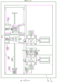
Fig. 1 is a schematic view of the overall structure of the present invention.
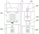
Fig. 2 is a top view of the present invention.
Fig. 3 is a view from a-a in fig. 2.
Fig. 4 is a view from B-B in fig. 2.
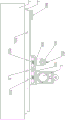
Fig. 5 is a schematic view of the second spindle and its on-line electrolytic sharpening device.
Fig. 6 is a view of the second spindle and its on-line electrolytic sharpening device in the direction of a-a.
Fig. 7 is a schematic view of an insulating holder in an in-line electrolytic sharpening device.
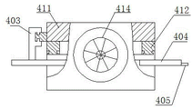
Fig. 8 is a schematic view of a measuring device.
Fig. 9 is a top view of the measuring device.
Fig. 10 is a schematic view of the spark truing device.
Fig. 11 is a top view of an electromagnetic centerless fixture and an electric spark.
In the figure, 1, a lathe bed, 2, a mounting platform, 3, a first spindle, 4, a measuring device, 5, a second spindle, 6, an X-direction moving platform, 601, an X-direction parallel guide rail, 602, an X-direction lead screw nut pair, 603, a motor, 604, a first Y-direction moving mechanism, 605, a second Y-direction moving mechanism, 7, an electromagnetic centerless clamp, 8, an electric spark grinding wheel shaping device, 9, an electric spark electrode shaping device, 11 and an online electrolytic sharpening device are arranged;
402. z-direction supporting plates 403, a grating ruler 404, a measuring support 405, a measuring head 411, a vertical arm 412, a Z-direction parallel guide rail 413, a lead screw nut pair 414 and a driving motor;
501. grinding wheel electric spindle 502, spindle seat 503, grinding wheel shaft 504, insulation coupling 505, axle box 506 and grinding wheel;
701. a clamp seat;
801. an electric spark negative electrode 802, an electrode electric spindle 803, an electric spark spray head 804 and a fixed support;
901. a base, 902, a tool rest base, 903, a tool rest, 904 and a turning tool;
1102. the electrolytic cell comprises an insulating support, 1103, an electrolytic negative electrode, 1104, an electrolytic spray head, 1111, a mounting seat, 1112, a guide rail, 1113, a linear motor, 1114 and a moving plate.
Detailed Description
The present invention will be described in further detail with reference to the accompanying drawings.
As shown in fig. 1 to 5, a horizontal double-spindle bearing ring grinding machine comprises a machine body 1, a mounting platform 2, a first spindle 3, a measuring device 4, a second spindle 5, an X-direction moving platform 6, an electromagnetic centerless fixture 7, an electric spark grinding wheel shaping device 8, an electric spark electrode shaping device 9 and a loading and unloading device 10, wherein the upper part of the machine body 1 is fixedly provided with the horizontal mounting platform 2 through bolts, one side of the upper surface of the mounting platform 2 in the X-axis direction is provided with an X-direction parallel guide rail 601, an X-direction lead screw nut pair 602 is arranged between the parallel guide rails 601, the X-direction moving platform 6 is arranged on the parallel guide rails 601 and runs on the parallel guide rails 601, the lower part of the X-direction moving platform 6 is fixedly connected with a nut connecting plate of the X-direction lead screw nut pair 602, the X-direction moving platform 6 is respectively provided with a first Y-direction moving mechanism 604 and a, a Y-direction planker is respectively arranged on the first Y-direction moving mechanism 604 and the second Y-direction moving mechanism 605, the electromagnetic centerless fixture 7 is arranged on the left side of the upper part of the X-direction moving platform 6 through the first Y-direction moving mechanism 604, the electric spark grinding wheel reshaping device 8 is arranged on the right side of the upper part of the X-direction moving platform 6 through the second Y-direction moving mechanism 605, a motor 603 for driving the X-direction lead screw to rotate is arranged on the mounting platform 2 at one end of the X-direction lead screw, the first spindle 3, the second spindle 5 and the electric spark electrode reshaping device 9 are sequentially and horizontally arranged on the other axial side of the mounting platform 2 from left to right, the measuring device 4 is arranged between the first spindle 3 and the second spindle 5, and the electric spark electrode reshaping device 9 is arranged on the right side of the second spindle 5; the first spindle 3 and the second spindle 5 are respectively composed of a grinding wheel electric spindle 501, a spindle seat 502, a grinding wheel spindle 503, an insulating coupling 504 and an axle box 505, wherein the grinding wheel electric spindle 501 is fixedly mounted on the mounting platform 2 through the spindle seat 502, the grinding wheel spindle 503 coaxial with the grinding wheel electric spindle 501 penetrates through the axle box 505, the axle box 505 is arranged above the mounting platform through an insulating plate, one end of the grinding wheel spindle 503 is insulated and fixedly connected with the output end of the grinding wheel electric spindle 501 through the insulating coupling 504, the grinding wheel 506 is mounted at the other end of the grinding wheel spindle 503, the grinding wheel 506 is a metal bond diamond grinding wheel, the grinding wheel 506 is electrically connected with a positive pole of a high-frequency pulse power supply, and the axes of the grinding wheel spindles 503 of the first spindle 3 and the second spindle 5 are.
As shown in fig. 5, 6 and 7, the first spindle 3 and the second spindle 5 are both provided with an online electrolytic sharpening device 11, the online electrolytic sharpening device 11 includes an X-axis moving mechanism, an insulating support 1102, an electrolytic negative electrode 1103 and an electrolytic spray nozzle 1104, the X-axis moving mechanism is composed of an installation seat 1111, a guide rail 1112, a linear motor 1113 and a moving plate 1114, the installation seat 1111 is fixedly disposed at the upper end of the axle box 505, the linear motor 1113 is disposed at one end of the installation seat 1111, the guide rail 1112 is disposed at the other end, the moving plate 1114 is driven by the linear motor 1113 and runs on the guide rail 1112, the upper end of the insulating support 1102 is fixedly connected with the moving plate 1114, the lower end of the insulating support is provided with the electrolytic negative electrode 1103 is an arc plate made of red copper as a whole, the electrolytic negative electrode 1103 is coaxially disposed at one side of the grinding wheel axle 503 and connected with the negative, the electrolytic spray nozzle 1104 for spraying the electrolyte penetrates through the lower end of the insulating bracket 1102, and the outlet of the electrolytic spray nozzle 1104 is positioned between the electrolytic negative electrode 1103 and the grinding wheel 506.
As shown in fig. 2, 4, 10 and 11, the spark grinding wheel truing device 8 includes a spark negative electrode 801, an electrode electric spindle 802 and a spark nozzle 803, the electrode electric spindle 802 is mounted on the carriage of the second Y-direction moving mechanism 605 through a fixing support 804, the spark negative electrode 801 made of red copper is mounted at the output end of the electrode electric spindle 802, the spark negative electrode 801 is connected with the negative electrode of the high-frequency pulse power supply, and the spark nozzle 803 for spraying spark electrolyte is fixedly disposed above the spark negative electrode 801.
As shown in fig. 2, 3, 8 and 9, the measuring device 4 includes a Z-direction displacement mechanism, a Z-direction supporting plate 402, a grating scale 403, a measuring bracket 404 and a measuring head 405, the Z-direction displacement mechanism consists of a vertical arm 411, a parallel guide rail 412, a lead screw nut pair 413 and a driving motor 414, wherein one side surface of the vertical arm 411 is provided with the parallel guide rail 412, the lead screw nut pair 413 is arranged between the parallel guide rails 412, the driving motor 414 is arranged at the top end of the vertical arm 411 and is connected with a lead screw of the lead screw nut pair 413 through a speed reducing mechanism, the Z-direction supporting plate 402 is fixedly connected with a nut connecting plate of a lead screw nut pair 413 and runs on a parallel guide rail 412, the measuring head 405 is arranged on the measuring support 404, the measuring support 404 is fixedly connected to the Z-direction support plate 402 and is positioned on one side of the vertical arm 411 facing the X-direction moving platform 6, the scale grating of the grating scale 403 is fixedly arranged on the other side of the vertical arm 411, and the grating reading head of the grating scale 403 is fixedly connected with the Z-direction support plate 402 through a connecting plate.
As shown in fig. 2, 4 and 11, the electromagnetic centerless clamp 7 is disposed on the carriage of the first Y-direction moving mechanism 604 through a clamp seat 701 capable of horizontally adjusting an angle, and a motor for driving the centerless clamp to rotate is disposed above the clamp seat 701 through a motor seat.
As shown in fig. 2, 5, 6, and 7, the electric spark electrode shaping apparatus 9 is composed of a base 901, a tool holder seat 902, a tool holder 903, and a turning tool 904, wherein the base 901 is disposed on the right side of the second spindle 5, the lower end of the base 901 is fixedly connected to the mounting platform 2, the upper end of the base 902 is provided with the tool holder seat 902, the upper end surface of the tool holder seat 902 is provided with a T-shaped groove, the tool holder 903 is mounted in the T-shaped groove of the tool holder seat 902 through a T-shaped bolt, the side surface of the tool holder 903 is provided with an open slot for accommodating the turning tool 904, and the side wall of the open slot located at.
The part of the utility model not detailed is prior art.
Claims (5)
1. The utility model provides a horizontal two main shaft bearing ring grinding machines, includes lathe bed (1), mounting platform (2), first main shaft (3), measuring device (4), second main shaft (5), X to moving platform (6), electromagnetism centerless anchor clamps (7), electric spark emery wheel shaping device (8) and electric spark electrode modification device (9), lathe bed (1) upper portion be provided with horizontally mounting platform (2) through bolt fastening, X axial one side is provided with X to parallel guide rail (601) above mounting platform (2), be provided with X between parallel guide rail (601) and to screw nut pair (602), X to moving platform (6) set up on parallel guide rail (601) and move on parallel guide rail (601), X links firmly characterized by to the nut connecting plate of screw nut pair (602) with X to the lower part of moving platform (6): the X-direction moving platform (6) is respectively provided with a first Y-direction moving mechanism (604) and a second Y-direction moving mechanism (605), the first Y-direction moving mechanism (604) and the second Y-direction moving mechanism (605) are respectively provided with a Y-direction carriage, the electromagnetic centerless fixture (7) is arranged on the left side of the upper part of the X-direction moving platform (6) through the first Y-direction moving mechanism (604), the electric spark grinding wheel shaping device (8) is arranged on the right side of the upper part of the X-direction moving platform (6) through the second Y-direction moving mechanism (605), a motor (603) for driving the X-direction lead screw to rotate is arranged on the mounting platform (2) at one end of the X-direction lead screw, the first main shaft (3), the second main shaft (5) and the electric spark electrode shaping device (9) are sequentially and horizontally arranged on the other side of the X-direction axial direction of the mounting platform (2) from left to right, the measuring device (4) is arranged between the first main shaft (3) and the, the electric spark electrode shaping device (9) is arranged on the right side of the second main shaft (5); the first main shaft (3) and the second main shaft (5) are respectively composed of a grinding wheel electric main shaft (501), a main shaft seat (502), a grinding wheel shaft (503), an insulating coupling (504) and an axle box (505), wherein the grinding wheel electric spindle (501) is fixedly arranged on the mounting platform (2) through a spindle seat (502), a grinding wheel shaft (503) which is coaxial with the grinding wheel electric spindle (501) is arranged in an axle box (505) in a penetrating way, the axle box (505) is arranged above the mounting platform (2) through an insulating plate, one end of the grinding wheel shaft (503) is insulated and fixedly connected with the output end of the grinding wheel electric spindle (501) through an insulating coupling (504), the other end of the grinding wheel shaft (503) is provided with a grinding wheel (506), the grinding wheel (506) is a metal bond diamond grinding wheel, the grinding wheel (506) is electrically connected with the anode of the high-frequency pulse power supply, the axes of the grinding wheel shafts (503) of the first main shaft (3) and the second main shaft (5) are parallel and have the same height;
all be provided with online electrolysis sharpening device (11) on first main shaft (3), second main shaft (5), online electrolysis sharpening device (11) include X axle moving mechanism, insulating support (1102), electrolysis negative electrode (1103) and electrolysis shower nozzle (1104), X axle moving mechanism comprises mount pad (1111), guide rail (1112), linear electric motor (1113) and movable plate (1114), mount pad (1111) is fixed to be set up in the upper end of axle box (505), one end is provided with linear electric motor (1113) above mount pad (1111), the other end is provided with guide rail (1112), movable plate (1114) are driven by linear electric motor (1113) and are moved on guide rail (1112), insulating support (1102) upper end links firmly with movable plate (1114), the lower extreme is provided with electrolysis negative electrode (1103), electrolysis negative electrode (1103) wholly is the arc board that red copper made, the electrolytic negative electrode (1103) is coaxially arranged on one side of the grinding wheel shaft (503) and connected with the negative electrode of the high-frequency pulse power supply, an electrolytic spray head (1104) for spraying electrolyte is arranged at the lower end of the insulating support (1102) in a penetrating mode, and the outlet of the electrolytic spray head (1104) is located between the electrolytic negative electrode (1103) and the grinding wheel (506).
2. The horizontal double-spindle bearing ring grinding machine as claimed in claim 1, wherein: the electric spark grinding wheel reshaping device (8) comprises an electric spark negative electrode (801), an electrode electric spindle (802) and an electric spark spray head (803), wherein the electrode electric spindle (802) is installed on a carriage of the second Y-direction moving mechanism (605) through a fixed support (804), the electric spark negative electrode (801) made of red copper is installed at the output end of the electrode electric spindle (802), the electric spark negative electrode (801) is connected with the negative electrode of a pulse power supply, and the electric spark spray head (803) used for spraying electric spark electrolyte is fixedly arranged above the electric spark negative electrode (801).
3. The horizontal double-spindle bearing ring grinding machine as claimed in claim 1, wherein: the measuring device (4) comprises a Z-direction displacement mechanism, a Z-direction supporting plate (402), a grating ruler (403), a measuring support (404) and a measuring head (405), wherein the Z-direction displacement mechanism consists of a vertical arm (411), parallel guide rails (412), a lead screw nut pair (413) and a driving motor (414), one side surface of the vertical arm (411) is provided with the parallel guide rails (412), the lead screw nut pair (413) is arranged between the parallel guide rails (412), the driving motor (414) is arranged at the top end of the vertical arm (411) and is connected with a lead screw of the lead screw nut pair (413) through a speed reducing mechanism, the Z-direction supporting plate (402) is fixedly connected with a nut connecting plate of the lead screw nut pair (413) and runs on the parallel guide rails (412), the measuring head (405) is fixedly connected on the measuring support (404), the measuring support (404) is arranged on the Z-direction supporting plate (402) and is positioned on one side of the vertical arm (411) facing the X-direction, and a scale grating of the grating ruler (403) is fixedly arranged on the other side of the vertical arm (411), and a grating reading head of the grating ruler (403) is fixedly connected with the Z-direction supporting plate (402) through a connecting plate.
4. The horizontal double-spindle bearing ring grinding machine as claimed in claim 1, wherein: the electromagnetic centerless clamp (7) is arranged on a carriage of the first Y-direction moving mechanism (604) through a clamp seat (701) with a horizontally adjustable angle, and a motor for driving the centerless clamp to rotate is arranged above the clamp seat (701) through a motor seat.
5. The horizontal double-spindle bearing ring grinding machine as claimed in claim 1, wherein: the electric spark electrode shaping device (9) is composed of a base (901), a tool rest seat (902), a tool rest (903) and a turning tool (904), wherein the base (901) is arranged on the right side of a second main shaft (5), the lower end of the base is fixedly connected with a mounting platform (2), the upper end of the base is provided with the tool rest seat (902), a T-shaped groove is formed in the upper end face of the tool rest seat (902), the tool rest (903) is mounted in the T-shaped groove of the tool rest seat (902) through a T-shaped bolt, an open groove used for containing the turning tool (904) is formed in the side face of the tool rest (903), and a fastening bolt used for clamping the turning tool (904) is arranged on the side wall of the upper portion.
Priority Applications (1)
| Application Number | Priority Date | Filing Date | Title |
|---|---|---|---|
| CN201921848090.4U CN210818922U (en) | 2019-10-30 | 2019-10-30 | Horizontal double-spindle bearing ring grinding machine |
Applications Claiming Priority (1)
| Application Number | Priority Date | Filing Date | Title |
|---|---|---|---|
| CN201921848090.4U CN210818922U (en) | 2019-10-30 | 2019-10-30 | Horizontal double-spindle bearing ring grinding machine |
Publications (1)
| Publication Number | Publication Date |
|---|---|
| CN210818922U true CN210818922U (en) | 2020-06-23 |
Family
ID=71275471
Family Applications (1)
| Application Number | Title | Priority Date | Filing Date |
|---|---|---|---|
| CN201921848090.4U Active CN210818922U (en) | 2019-10-30 | 2019-10-30 | Horizontal double-spindle bearing ring grinding machine |
Country Status (1)
| Country | Link |
|---|---|
| CN (1) | CN210818922U (en) |
Cited By (2)
| Publication number | Priority date | Publication date | Assignee | Title |
|---|---|---|---|---|
| CN112917340A (en) * | 2021-01-16 | 2021-06-08 | 北京工业大学 | Bearing raceway accurate progressive precision forming grinding machine tool based on ELID grinding |
| CN113843689A (en) * | 2021-09-24 | 2021-12-28 | 中国科学院工程热物理研究所 | High-speed blade tip grinding equipment |
-
2019
- 2019-10-30 CN CN201921848090.4U patent/CN210818922U/en active Active
Cited By (2)
| Publication number | Priority date | Publication date | Assignee | Title |
|---|---|---|---|---|
| CN112917340A (en) * | 2021-01-16 | 2021-06-08 | 北京工业大学 | Bearing raceway accurate progressive precision forming grinding machine tool based on ELID grinding |
| CN113843689A (en) * | 2021-09-24 | 2021-12-28 | 中国科学院工程热物理研究所 | High-speed blade tip grinding equipment |
Similar Documents
| Publication | Publication Date | Title |
|---|---|---|
| CN108500786B (en) | Ultra-precise forming and grinding device and method for bearing track | |
| CN110666637A (en) | Horizontal double-spindle bearing ring grinding machine | |
| EP3584035B1 (en) | Universal automatic composite grinding wheel finisher | |
| CN210818922U (en) | Horizontal double-spindle bearing ring grinding machine | |
| CN213828500U (en) | Multi-station grinding machine fine adjustment mechanism | |
| CN201872026U (en) | Double-grinding-head thermal extension noncontact measuring mechanism of guide rail shaping grinding machine | |
| CN110666638A (en) | Novel bearing inner race raceway grinding machine | |
| CN102059652B (en) | Thermal-elongation non-contact measuring mechanism of double grinding heads of guiding rail forming grinding machine | |
| CN210818923U (en) | Grinding wheel dressing device of bearing ring raceway grinding machine | |
| CN113579955A (en) | Double-station silicon carbide crystal shaping all-in-one machine | |
| CN104308298A (en) | High-accuracy numerical control electrolytic grinding machine tool for processing ultrathin and superhard conductive material | |
| CN210790405U (en) | Novel bearing inner race raceway grinding machine | |
| CN216422106U (en) | Force control compensation device and five-axis numerical control grinding machine | |
| CN114750005A (en) | Roller way device in multidimensional ultrasonic ELID grinding processing bearing | |
| CN211439305U (en) | Disc brake pad inner and outer arc edge chamfer grinding machine | |
| CN115255528A (en) | Cut-in type cylindrical roller electrolytic superfinishing machine and machining method | |
| CN213532070U (en) | Polishing equipment for machining production | |
| CN114789379A (en) | Vertical grinding machine for outer contour of non-revolving body conical workpiece and grinding method | |
| CN212794504U (en) | Multi-station spherical roller outer diameter super-fine grinder | |
| CN114871947A (en) | Abrasion detection and in-place dressing device for grinding wheel | |
| CN210307196U (en) | Bearing rolling element grinding device | |
| CN109719592B (en) | Automatic pencil lead grinding device | |
| CN203141120U (en) | Two-dimensional adjustable support for cutter bar machining | |
| CN110625482A (en) | Grinding wheel dressing device of bearing ring raceway grinding machine | |
| CN219561666U (en) | Numerical control gear grinding machine with tool grinding device |
Legal Events
| Date | Code | Title | Description |
|---|---|---|---|
| GR01 | Patent grant | ||
| GR01 | Patent grant |