CN114750005A - Roller way device in multidimensional ultrasonic ELID grinding processing bearing - Google Patents
Roller way device in multidimensional ultrasonic ELID grinding processing bearing Download PDFInfo
- Publication number
- CN114750005A CN114750005A CN202210365473.6A CN202210365473A CN114750005A CN 114750005 A CN114750005 A CN 114750005A CN 202210365473 A CN202210365473 A CN 202210365473A CN 114750005 A CN114750005 A CN 114750005A
- Authority
- CN
- China
- Prior art keywords
- axis
- horizontal
- ultrasonic
- wireless transmission
- bearing
- Prior art date
- Legal status (The legal status is an assumption and is not a legal conclusion. Google has not performed a legal analysis and makes no representation as to the accuracy of the status listed.)
- Pending
Links
Images

Classifications
-
- B—PERFORMING OPERATIONS; TRANSPORTING
- B24—GRINDING; POLISHING
- B24B—MACHINES, DEVICES, OR PROCESSES FOR GRINDING OR POLISHING; DRESSING OR CONDITIONING OF ABRADING SURFACES; FEEDING OF GRINDING, POLISHING, OR LAPPING AGENTS
- B24B1/00—Processes of grinding or polishing; Use of auxiliary equipment in connection with such processes
- B24B1/04—Processes of grinding or polishing; Use of auxiliary equipment in connection with such processes subjecting the grinding or polishing tools, the abrading or polishing medium or work to vibration, e.g. grinding with ultrasonic frequency
-
- B—PERFORMING OPERATIONS; TRANSPORTING
- B24—GRINDING; POLISHING
- B24B—MACHINES, DEVICES, OR PROCESSES FOR GRINDING OR POLISHING; DRESSING OR CONDITIONING OF ABRADING SURFACES; FEEDING OF GRINDING, POLISHING, OR LAPPING AGENTS
- B24B41/00—Component parts such as frames, beds, carriages, headstocks
- B24B41/06—Work supports, e.g. adjustable steadies
-
- B—PERFORMING OPERATIONS; TRANSPORTING
- B24—GRINDING; POLISHING
- B24B—MACHINES, DEVICES, OR PROCESSES FOR GRINDING OR POLISHING; DRESSING OR CONDITIONING OF ABRADING SURFACES; FEEDING OF GRINDING, POLISHING, OR LAPPING AGENTS
- B24B53/00—Devices or means for dressing or conditioning abrasive surfaces
- B24B53/06—Devices or means for dressing or conditioning abrasive surfaces of profiled abrasive wheels
- B24B53/07—Devices or means for dressing or conditioning abrasive surfaces of profiled abrasive wheels by means of forming tools having a shape complementary to that to be produced, e.g. blocks, profile rolls
-
- C—CHEMISTRY; METALLURGY
- C25—ELECTROLYTIC OR ELECTROPHORETIC PROCESSES; APPARATUS THEREFOR
- C25F—PROCESSES FOR THE ELECTROLYTIC REMOVAL OF MATERIALS FROM OBJECTS; APPARATUS THEREFOR
- C25F3/00—Electrolytic etching or polishing
- C25F3/02—Etching
Abstract
A multi-dimensional ultrasonic ELID grinding processing bearing inner raceway device comprises a cutter ultrasonic part, an ELID trimming part, a workpiece ultrasonic part, a workpiece clamping part and a forming grinding wheel; the ultrasonic part of the cutter is connected with a machine tool spindle through a cutter handle, the machine tool spindle is vertically arranged downwards, and a forming grinding wheel is fixedly arranged at the lower end of the ultrasonic part of the cutter, so that the ultrasonic vibration is added on the forming grinding wheel; two electrodes of the ELID trimming part are respectively connected with the center and the circumferential edge of the forming grinding wheel, so that the on-line electrolytic trimming of the forming grinding wheel is realized; the workpiece ultrasonic part is fixed on the machine tool workbench, and the workpiece clamping part is arranged on the workpiece ultrasonic part, so that the workpiece ultrasonic vibration is added. The invention can finish the precision grinding of the inner raceway of the bearing, and simultaneously, the processing efficiency and the processing quality of the workpiece can be greatly improved by the addition of the multidimensional ultrasonic action of the cutter and the workpiece, thereby realizing the super-grinding processing of the inner raceway of the precision bearing.
Description
Technical Field
The invention belongs to the technical field of bearing strengthening processing, and particularly relates to a multi-dimensional ultrasonic ELID grinding processing bearing inner raceway device.
Background
The high-precision bearing plays an important role in the normal operation of aerospace engines, high-precision machine tools, high-speed railways, high-precision instruments and meters and the like. The bearing ring channel is the working surface of the bearing, and the shape precision and the surface quality of the bearing ring channel influence the precision, the service life, the vibration and other properties of the bearing. At present, the machining procedure of the bearing ring channel is mainly forming grinding, the forming grinding machining of the bearing ring channel becomes an effective way for machining a high-precision bearing, but the forming grinding surface quality is low, the grinding heat generated in the machining process is not easy to reduce, and the grinding chips are easy to scrape the surface of a grinding wheel and a workpiece, so that the grinding wheel is blocked and the grinding quality is reduced. Meanwhile, the machining working condition is severe, and the risk of abrasion and contact fatigue failure caused by relative motion of the inner and outer ring raceways and the rolling elements of the bearing is high under the combined action of multiple factors such as high stress, high speed, high temperature and the like. Therefore, the surface quality and the processing efficiency of the bearing channel forming grinding are improved, the online dressing of a grinding wheel is solved, and the problem to be solved in the high-precision bearing processing is solved by strengthening the inner ring raceway and the outer ring raceway of the bearing and improving the fatigue life of the inner ring raceway and the outer ring raceway of the bearing.
High is given birth to ELID abrasive machining surface quality, utilizes ELID forming grinding can effectively deal with multi-variety, small batch's high-accuracy bearing ring channel forming grinding surface, has realized the online of emery wheel and has maintained, reduces the manufacturing cost of high accuracy bearing, but machining efficiency is lower, also can not realize strengthening in order to improve its fatigue life of bearing inner and outer lane raceway.
In the existing surface strengthening technology, such as shot blasting, sand blasting or ultrasonic shot blasting, the depth of a strengthening layer is limited, the roughness of the working surface of a bearing raceway is high, and in order to ensure the roughness of the working surface of the bearing, the surface of the shot blasting or the sand blasting needs to be ground or grinded, so that the strengthening layer is removed and loses the strengthening effect. Researches find that the ultrasonic auxiliary grinding can improve the processing efficiency and the processing quality, and the additional cavitation effect can realize the ultrasonic cleaning of fine parts.
Therefore, how to combine the multidimensional ultrasonic vibration effect and the ELID electrolysis effect to make up for each other and achieve complementary advantages is a technical problem which needs to be solved urgently.
Disclosure of Invention
In order to overcome the defects in the prior art, the invention provides the multidimensional ultrasonic ELID grinding processing bearing inner raceway device which has high processing efficiency, carries out ELID electrolytic finishing on a grinding wheel during grinding and has high processing precision.
In order to solve the technical problem, the invention adopts the following technical scheme: a multi-dimensional ultrasonic ELID grinding processing bearing inner raceway device comprises a cutter ultrasonic part, an ELID trimming part, a workpiece ultrasonic part, a workpiece clamping part and a forming grinding wheel; the ultrasonic part of the cutter is connected with a machine tool spindle through a cutter handle, the machine tool spindle is vertically arranged downwards, and a forming grinding wheel is fixedly arranged at the lower end of the ultrasonic part of the cutter, so that the ultrasonic vibration is added on the forming grinding wheel; two electrodes of the ELID trimming part are respectively and electrically connected with the center and the circumferential edge of the formed grinding wheel, so that the on-line electrolytic trimming of the formed grinding wheel is realized; the workpiece ultrasonic part is fixed on the machine tool workbench, and the workpiece clamping part is arranged on the workpiece ultrasonic part, so that the workpiece ultrasonic vibration is added.
The cutter ultrasonic part comprises a fixed cylinder, a Z-axis ultrasonic generator, a Z-axis wireless transmission upper disc assembly, a Z-axis wireless transmission lower disc assembly, a Z-axis transducer and a Z-axis amplitude transformer, wherein the lower end of the fixed cylinder is provided with an opening, the upper end of the fixed cylinder is fixedly connected with the lower end of the cutter handle in a coaxial manner, the Z-axis wireless transmission upper disc assembly and the Z-axis wireless transmission lower disc assembly are both sleeved outside the fixed cylinder, a plane gap is formed between the lower side surface of the Z-axis wireless transmission upper disc assembly and the upper side surface of the Z-axis wireless transmission lower disc assembly, the upper end of the Z-axis wireless transmission upper disc assembly is connected with a fixed part of a machine tool spindle, an inner circle of the Z-axis wireless transmission lower disc assembly is fixedly connected with an outer circle of the fixed cylinder, the Z-axis amplitude transformer is coaxially arranged with the machine tool spindle, a flange is integrally arranged at the upper end of the Z-axis amplitude transformer, the flange is connected with the lower end of the fixed cylinder through a screw, the Z-axis transducer is arranged on the upper surface of the flange and positioned in the fixed cylinder, the energy converter is connected with the flange plate and the Z-axis amplitude transformer through the upper connecting bolt, the Z-axis ultrasonic generator is connected with the Z-axis wireless transmission upper disc assembly through the first lead, the Z-axis wireless transmission lower disc assembly is connected with the Z-axis energy converter through the second lead which radially penetrates through the fixing cylinder, and the lower end of the Z-axis amplitude transformer is fixedly connected with the forming grinding wheel through the lower connecting bolt.
The workpiece ultrasonic part comprises a fixed frame, a driving motor, a lower bearing seat, an upper bearing seat, a driving shaft, a horizontal ultrasonic generator, a horizontal wireless transmission upper disc assembly, a horizontal wireless transmission lower disc assembly, a horizontal tray, an X-axis transducer, an X-axis flange bracket, an X-axis amplitude transformer, a Y-axis transducer, a Y-axis flange bracket and a Y-axis amplitude transformer;
the fixed frame, the driving motor and the lower bearing seat are arranged on a machine tool workbench, the upper bearing seat is arranged on the fixed frame, the upper bearing seat and the lower bearing seat are arranged in a vertically corresponding manner, the lower end of the driving shaft is rotatably connected in the lower bearing seat, the upper end of the driving shaft penetrates through the upper bearing seat and is fixedly connected with the center of the bottom surface of the horizontal tray, the driving motor is in transmission connection with the driving shaft through a transmission belt, the horizontal wireless transmission lower tray assembly is fixedly arranged at the top of the fixed frame, the horizontal wireless transmission upper tray assembly is fixedly arranged at the bottom surface of the horizontal tray, a horizontal gap is formed between the horizontal wireless transmission lower tray assembly and the horizontal wireless transmission upper tray assembly, the X-axis flange bracket and the Y-axis flange bracket are both fixedly arranged on the upper surface of the horizontal tray, the X-axis transducer and the X-axis amplitude transformer are both arranged on the X-axis flange bracket, the Y-axis transducer and the Y-axis amplitude transformer are both arranged on the Y-axis flange bracket, and the central line of the X-axis amplitude transformer are vertical to each other, the workpiece clamping part is arranged above the horizontal tray and is respectively connected with the thinner ends of the X-axis amplitude transformer and the Y-axis amplitude transformer through stud bolts;
The horizontal ultrasonic generator is connected with the horizontal wireless transmission lower disc assembly through a third lead, the horizontal wireless transmission upper disc assembly is connected with the X-axis transducer through a fourth lead, and the horizontal wireless transmission upper disc assembly is connected with the Y-axis transducer through a fifth lead.
The workpiece clamping part comprises a circular horizontal supporting plate, a bearing ring clamp is arranged on the horizontal supporting plate, and an outer ring of the bearing workpiece is clamped in the bearing ring clamp.
The mounting bracket top center is equipped with the mounting groove, and level wireless transmission lower wall subassembly sets up in the mounting groove, and level wireless transmission lower wall subassembly upper surface flushes with the mount top.
The ELID trimming part comprises an ELID power supply, an electrode connecting hanger, an anode carbon brush and a cathode copper pole, wherein the anode carbon brush and the cathode copper pole are respectively fixedly arranged on the electrode connecting hanger, the anode carbon brush is in sliding contact with the excircle of the Z-axis amplitude transformer, the cathode copper pole extends into the bearing workpiece and has a certain gap with the excircle of the forming grinding wheel, the ELID power supply is connected with the anode carbon brush through a sixth wire, and the ELID power supply is connected with the cathode copper pole through a seventh wire.
The electrode connecting hanger comprises an upper horizontal rod, a vertical fixed pipe and a vertical telescopic pipe, the utility model discloses a machine tool main shaft, including positive pole horizontal connecting pipe, negative pole horizontal connecting pipe and the vertical connecting pipe of negative pole, the fixed part of spirit level one end fixed connection at the lathe main shaft, the spirit level bottom is equipped with the guide rail along length direction, vertical fixed pipe upper end is equipped with along the gliding slider of guide rail, vertical flexible pipe upper portion is inserted and is established in vertical fixed pipe and fix a position through the jackscrew, positive pole horizontal connecting pipe is located negative pole horizontal connecting pipe top, positive pole horizontal connecting pipe one end is connected with vertical flexible pipe through last connecting pipe clamp, the fixed carbon brush that establishes in positive pole horizontal connecting pipe other end, vertical flexible pipe lower extreme is connected with negative pole horizontal connecting pipe one end is perpendicular, the negative pole horizontal connecting pipe other end is connected with negative pole vertical connecting pipe upper end through connecting pipe clamp and adjusting nut down, the negative pole copper utmost point is fixed to be established at the vertical connecting pipe lower extreme of negative pole.
The vertical fixed rod is provided with a handle for driving the sliding block at the upper end of the vertical fixed rod to move along the guide rail at the bottom of the upper horizontal rod.
The sixth wire penetrates through the anode horizontal connecting pipe to be connected with the anode carbon brush, and the seventh wire sequentially penetrates through the cathode horizontal connecting pipe and the cathode vertical connecting pipe to be connected with the cathode copper pole.
By adopting the technical scheme, the specific process of grinding the inner raceway (circular ring shape) of the bearing comprises the following steps: the outer ring of the bearing workpiece is placed in a bearing ring clamp on the horizontal supporting plate, the bearing ring clamp can adopt a pneumatic clamping mechanism, after the bearing workpiece is clamped by the bearing ring clamp, the machine tool is started, a driving motor, a horizontal ultrasonic generator, a Z-axis ultrasonic generator and an ELID power supply are started, a main shaft of the machine tool sequentially drives a tool handle, a fixing cylinder, a Z-axis wireless transmission lower disc assembly, a Z-axis amplitude transformer and a forming grinding wheel to rotate at a high speed, the Z-axis wireless transmission upper disc assembly is fixed and does not move, the Z-axis wireless transmission lower disc assembly converts ultrasonic high-frequency electric energy to a Z-axis transducer in the tool handle which rotates at a high speed through an electromagnetic induction principle, the Z-axis transducer converts the received ultrasonic high-frequency electric energy into ultrasonic high-frequency mechanical vibration, and the ultrasonic vibration is amplified and transmitted to the forming grinding wheel arranged at the lower end of the Z-axis amplitude transformer through the Z-axis amplitude transformer in threaded connection with an upper connecting bolt. And the molding grinding wheel extends into the bearing workpiece to carry out ultrasonic grinding processing on the inner raceway of the bearing workpiece. Meanwhile, a driving motor drives a driving shaft to rotate, the driving shaft drives a horizontal tray and a horizontal wireless transmission upper tray assembly to rotate, an X-axis transducer, an X-axis flange bracket, an X-axis amplitude transformer, a Y-axis transducer, a Y-axis flange bracket and a Y-axis amplitude transformer which are arranged on the horizontal tray also rotate along with the rotation, a horizontal supporting plate, a bearing ring clamp and a bearing workpiece which are horizontally arranged on the X-axis amplitude transformer and the Y-axis amplitude transformer also rotate along with the rotation, the horizontal wireless transmission upper tray assembly converts ultrasonic high-frequency electric energy to the X-axis transducer and the Y-axis transducer which rotate at high speed through an electromagnetic induction principle when rotating, the X-axis transducer and the Y-axis transducer convert the received ultrasonic high-frequency electric energy into ultrasonic high-frequency mechanical vibration, and then the ultrasonic vibration is expanded and transmitted to the horizontal supporting plate and the bearing workpiece through the X-axis amplitude transformer and the Y-axis amplitude transformer, so that auxiliary two-dimensional ultrasonic vibration is also generated when the workpiece rotates, and the three-dimensional ultrasonic is formed by the ultrasonic vibration of the Z axis of the formed grinding wheel, so that the grinding precision is improved.
During grinding operation, the control handle can move the vertical fixing tube to horizontally move along the guide rail at the bottom of the upper horizontal rod so as to enable the anode carbon brush to be in sliding contact with the excircle of the Z-axis amplitude transformer, and the cathode copper pole extends into the bearing workpiece and has a certain gap with the excircle of the forming grinding wheel. Through adjusting, the size of the vertical telescopic pipe in the vertical fixed pipe is fixed by the jackscrew, so that the height of the cathode copper electrode is adjusted to be consistent with the height of the forming grinding wheel. The adjusting nut can be used for finely adjusting the radial position of the cathode vertical connecting pipe (cathode copper pole) so as to better enable the cathode copper pole and the forming grinding wheel to have a certain gap. The Z-axis amplitude transformer and the forming grinding wheel matrix are made of conductive materials, and the forming grinding wheel is a cast iron binder diamond grinding wheel, so that the forming grinding wheel is connected with the anode of an ELID power supply, the cathode copper pole is connected with the ELID power supply and is a cathode, when the ELID power supply is electrified, the forming grinding wheel and the cathode copper pole perform electrolytic reaction, and online electrolytic finishing of the forming grinding wheel is ensured.
The invention provides a device for grinding and processing an inner raceway of a bearing by using multidimensional ultrasonic ELID (ultrasonic imaging) in consideration of the processing requirements of the inner raceway and the outer raceway of the bearing, which combines the multidimensional ultrasonic vibration effect and the ELID electrolysis effect to make up for the deficiencies of the multidimensional ultrasonic vibration effect and the ELID electrolysis effect, thereby realizing advantage complementation. On one hand, the ELID electrolysis realizes the online finishing of the grinding wheel, and ensures the sharpness and the contour of abrasive particles on the grinding wheel in the processing process; on the one hand, the addition of the multi-dimensional ultrasonic effect not only realizes the ultrasonic strengthening on the surface of the workpiece and improves the fatigue life of the workpiece, but also realizes the clear effect on the adhesive substances such as abrasive dust, electrolyte and the like at narrow and small gaps in the grinding process by the ultrasonic cavitation effect, and ensures the stable, high-quality and high-efficiency operation of the processing process. The invention not only can realize the on-line electrolytic dressing of the formed grinding wheel, but also can combine the ultrasonic ELID composite grinding system under various modes.
In conclusion, the invention has the advantages of reasonable structural design, convenient use and the like, can realize multidimensional ultrasonic grinding and ELID electrolytic finishing of the inner raceway of the precision bearing through one-time clamping and grinding, saves the processing tool changing time, improves the processing precision and the processing quality, and ensures the processing efficiency, the processing precision and the processing quality of the inner raceway of the precision bearing. The invention can finish the precision grinding of the inner raceway of the bearing, and simultaneously, the processing efficiency and the processing quality of the workpiece can be greatly improved by the addition of the multidimensional ultrasonic action of the cutter and the workpiece, thereby realizing the super-grinding processing of the inner raceway of the precision bearing. The structure of the invention can be placed horizontally besides being placed vertically on a machine tool, and is all within the protection range.
Drawings
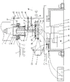
FIG. 1 is a schematic view of the structure of the apparatus of the present invention;
FIG. 2 is a top view of the ultrasonic portion of the workpiece of FIG. 1.
Detailed Description
As shown in fig. 1 and fig. 2, the multi-dimensional ultrasonic ELID grinding processing bearing inner raceway device of the invention comprises a cutter ultrasonic part, an ELID trimming part, a workpiece ultrasonic part, a workpiece clamping part and a forming grinding wheel 1; the ultrasonic part of the cutter is connected with a machine tool spindle 4 through a cutter handle 3, the machine tool spindle 4 is vertically arranged downwards, and a forming grinding wheel 1 is fixedly arranged at the lower end of the ultrasonic part of the cutter, so that ultrasonic vibration is added to the forming grinding wheel 1; two electrodes of the ELID trimming part are respectively and electrically connected with the center and the circumferential edge of the formed grinding wheel 1, so that the on-line electrolytic trimming of the formed grinding wheel 1 is realized; the workpiece ultrasonic part is fixed on a machine tool workbench 5, and the workpiece clamping part is arranged on the workpiece ultrasonic part, so that the workpiece ultrasonic vibration is added.
The ultrasonic part of the cutting tool comprises a fixed cylinder 6, a Z-axis ultrasonic generator 7, a Z-axis wireless transmission upper disc assembly 8, a Z-axis wireless transmission lower disc assembly 9, a Z-axis transducer 10 and a Z-axis amplitude transformer 11, wherein the lower end of the fixed cylinder 6 is provided with an opening, the upper end of the fixed cylinder 6 is fixedly connected with the lower end of a cutter handle 3 in a coaxial line manner, the Z-axis wireless transmission upper disc assembly 8 and the Z-axis wireless transmission lower disc assembly 9 are both sleeved outside the fixed cylinder 6, a plane gap is formed between the lower side surface of the Z-axis wireless transmission upper disc assembly 8 and the upper side surface of the Z-axis wireless transmission lower disc assembly 9, the upper end of the Z-axis wireless transmission upper disc assembly 8 is connected with a fixed part of a machine tool spindle 4, the inner circle of the Z-axis wireless transmission lower disc assembly 9 is fixedly connected with the outer circle of the fixed cylinder 6, the Z-axis amplitude transformer 11 is arranged in a coaxial line with the machine tool spindle 4, the upper end of the Z-axis amplitude transformer 11 is integrally provided with a flange 12, the flange 12 is connected with the lower end of the fixed cylinder 6 through screws, the Z-axis transducer 10 is arranged on the upper surface of the flange plate 12 and located in the fixed cylinder 6, the transducer is connected with the flange plate 12 and the Z-axis amplitude transformer 11 through an upper connecting bolt, the Z-axis ultrasonic generator 7 is connected with the Z-axis wireless transmission upper disc assembly 8 through a first lead, the Z-axis wireless transmission lower disc assembly 9 is connected with the Z-axis transducer 10 through a second lead which radially penetrates through the fixed cylinder 6, and the lower end of the Z-axis amplitude transformer 11 is fixedly connected with the forming grinding wheel 1 through a lower connecting bolt.
The workpiece ultrasonic part comprises a fixed frame 2, a driving motor 13, a lower bearing seat 14, an upper bearing seat 15, a driving shaft 16, a horizontal ultrasonic generator 17, a horizontal wireless transmission upper disc assembly 18, a horizontal wireless transmission lower disc assembly 19, a horizontal tray 20, an X-axis transducer 21, an X-axis flange bracket 22, an X-axis amplitude transformer 23, a Y-axis transducer 24, a Y-axis flange bracket 25 and a Y-axis amplitude transformer 26;
the fixed frame 2, the driving motor 13 and the lower bearing seat 14 are arranged on the machine tool workbench 5, the upper bearing seat 15 is arranged on the fixed frame 2, the upper bearing seat 15 and the lower bearing seat 14 are arranged up and down correspondingly, the lower end of the driving shaft 16 is rotatably connected in the lower bearing seat 14, the upper end of the driving shaft 16 passes through the upper bearing seat 15 and is fixedly connected with the center of the bottom surface of the horizontal tray 20, the driving motor 13 is in transmission connection with the driving shaft 16 through a transmission belt, the horizontal wireless transmission lower tray assembly 19 is fixedly arranged at the top of the fixed frame 2, the horizontal wireless transmission upper tray assembly 18 is fixedly arranged at the bottom surface of the horizontal tray 20, a horizontal gap is formed between the horizontal wireless transmission lower tray assembly 19 and the horizontal wireless transmission upper tray assembly 18, the X-axis flange bracket 22 and the Y-axis flange bracket 25 are both fixedly arranged on the upper surface of the horizontal tray 20, the X-axis transducer 21 and the X-axis amplitude transformer 23 are both arranged on the X-axis flange bracket 22, the Y-axis transducer 24 and the Y-axis amplitude transformer 26 are both arranged on the Y-axis flange bracket 25, the central lines of the X-axis amplitude transformer 23 and the Y-axis amplitude transformer 26 are vertical, the workpiece clamping part is arranged above the horizontal tray 20, and the workpiece clamping part is respectively connected with the thinner ends of the X-axis amplitude transformer 23 and the Y-axis amplitude transformer 26 through stud bolts;
The horizontal ultrasonic generator 17 is connected with the horizontal wireless transmission lower disc assembly 19 through a third lead, the horizontal wireless transmission upper disc assembly 18 is connected with the X-axis transducer 21 through a fourth lead, and the horizontal wireless transmission upper disc assembly 18 is connected with the Y-axis transducer 24 through a fifth lead.
The workpiece clamping part comprises a circular horizontal supporting plate 27, a bearing ring clamp 28 is arranged on the horizontal supporting plate 27, and the outer ring of a bearing workpiece 29 is clamped in the bearing ring clamp 28.
The center of the top of the fixing frame 2 is provided with a mounting groove, the horizontal wireless transmission lower disc assembly 19 is arranged in the mounting groove, and the upper surface of the horizontal wireless transmission lower disc assembly 19 is flush with the top of the fixing frame 2.
The ELID trimming part comprises an ELID power supply 44, an electrode connecting hanger, an anode carbon brush 30 and a cathode copper electrode 31, wherein the anode carbon brush 30 and the cathode copper electrode 31 are respectively fixedly arranged on the electrode connecting hanger, the anode carbon brush 30 is in sliding contact with the excircle of the Z-axis amplitude transformer 11, the cathode copper electrode 31 extends into the bearing workpiece 29 and has a certain gap with the excircle of the forming grinding wheel 1, the ELID power supply 44 is connected with the anode carbon brush 30 through a sixth lead, and the ELID power supply 44 is connected with the cathode copper electrode 31 through a seventh lead.
The electrode connecting hanger comprises an upper horizontal rod 32, a vertical fixed pipe 33, a vertical telescopic pipe 34, an anode horizontal connecting pipe 35, a cathode horizontal connecting pipe 36 and a cathode vertical connecting pipe 37, one end of the upper horizontal rod 32 is fixedly connected with the fixed part of the machine tool spindle 4, a guide rail is arranged at the bottom of the upper horizontal rod 32 along the length direction, a slide block 38 sliding along the guide rail is arranged at the upper end of the vertical fixed pipe 33, the upper part of the vertical telescopic pipe 34 is inserted in the vertical fixed pipe 33 and is positioned by a jackscrew 39, the anode horizontal connecting pipe 35 is positioned above the cathode horizontal connecting pipe 36, one end of the anode horizontal connecting pipe 35 is connected with the vertical telescopic pipe 34 through an upper connecting pipe clamp 40, an anode carbon brush 30 is fixedly arranged at the other end of the anode horizontal connecting pipe 35, the lower end of the vertical telescopic pipe 34 is vertically connected with one end of the cathode horizontal connecting pipe 36, the other end of the cathode horizontal connecting pipe 36 is connected with the upper end of the cathode vertical connecting pipe 37 through a lower connecting pipe clamp 41 and an adjusting nut 42, the cathode copper electrode 31 is fixedly arranged at the lower end of the cathode vertical connecting pipe 37.
The vertical fixing rod is provided with a handle 43 for driving the sliding block 38 at the upper end of the vertical fixing rod to move along the guide rail at the bottom of the upper horizontal rod 32.
The sixth lead passes through the anode horizontal connecting pipe 35 to be connected with the anode carbon brush 30, and the seventh lead sequentially passes through the cathode horizontal connecting pipe 36 and the cathode vertical connecting pipe 37 to be connected with the cathode copper electrode 31.
The invention carries out grinding processing operation on the inner raceway (circular ring shape) of the bearing, which comprises the following specific processes: the outer ring of the bearing workpiece 29 is placed in a bearing ring clamp 28 on a horizontal supporting plate 27, the bearing ring clamp 28 can adopt a pneumatic clamping mechanism, after the bearing workpiece 29 is clamped by the bearing ring clamp 28, the machine tool is started, a driving motor 13, a horizontal ultrasonic generator 17, a Z-axis ultrasonic generator 7 and an ELID power supply 44 are started, a machine tool spindle 4 sequentially drives a tool shank 3, a fixed cylinder 6, a Z-axis wireless transmission lower disc assembly, a Z-axis amplitude transformer 11 and a forming grinding wheel 1 to rotate at a high speed, the Z-axis wireless transmission upper disc assembly 8 is fixed and fixed, the Z-axis wireless transmission lower disc assembly 9 converts ultrasonic high-frequency electric energy to a Z-axis transducer 10 in the tool shank 3 which rotates at a high speed through an electromagnetic induction principle, the Z-axis transducer 10 converts the received ultrasonic high-frequency electric energy into ultrasonic high-frequency mechanical vibration, and the ultrasonic vibration is expanded and transmitted to the forming grinding wheel 1 arranged at the lower end of the Z-axis amplitude transformer 11 through the Z-axis amplitude transformer 11 in threaded connection with an upper connecting bolt. The formed grinding wheel 1 extends into the bearing workpiece 29 to carry out ultrasonic grinding processing on the roller way in the bearing workpiece 29. Meanwhile, the driving motor 13 drives the driving shaft 16 to rotate, the driving shaft 16 drives the horizontal tray 20 and the horizontal wireless transmission upper tray assembly 18 to rotate, the X-axis transducer 21, the X-axis flange bracket 22, the X-axis amplitude transformer 23, the Y-axis transducer 24, the Y-axis flange bracket 25 and the Y-axis amplitude transformer 26 which are arranged on the horizontal tray 20 also rotate along with the rotation, the horizontal supporting plate 27, the bearing ring clamp 28 and the bearing workpiece 29 which are horizontally arranged on the X-axis amplitude transformer 23 and the Y-axis amplitude transformer 26 also rotate along with the rotation, the horizontal wireless transmission upper tray assembly 18 converts the ultrasonic high-frequency electric energy into the X-axis transducer 21 and the Y-axis transducer 24 which rotate at high speed through an electromagnetic induction principle during the rotation, the X-axis transducer 21 and the Y-axis transducer 24 convert the received ultrasonic high-frequency electric energy into ultrasonic high-frequency mechanical vibration, and then the ultrasonic vibration is amplified and transmitted to the horizontal supporting plate 27 and the bearing workpiece 29 through the X-axis amplitude transformer 23 and the Y-axis amplitude transformer 26, therefore, the workpiece also generates auxiliary two-dimensional ultrasonic vibration when rotating, and forms three-dimensional ultrasonic with the Z-axis ultrasonic vibration of the forming grinding wheel 1, thereby improving the grinding precision.
During the grinding operation, the control handle 43 can move the vertical fixing tube 33 to move horizontally along the guide rail at the bottom of the upper horizontal rod 32, so that the anode carbon brush 30 is in sliding contact with the outer circle of the Z-axis amplitude transformer 11, and the cathode copper electrode 31 extends into the bearing workpiece 29 and has a certain gap with the outer circle of the forming grinding wheel 1. Through adjustment, the size of the vertical telescopic pipe 34 in the vertical fixing pipe 33 is adjusted, and the vertical telescopic pipe 34 is fixed through a jackscrew 39, so that the height of the cathode copper pole 31 is adjusted to be consistent with the height of the forming grinding wheel 1. The adjusting nut 42 can be used to fine-tune the radial position of the cathode vertical connecting pipe 37 (cathode copper electrode 31) to better enable the cathode copper electrode 31 to have a certain clearance with the formed grinding wheel 1. The Z-axis amplitude transformer 11 and the forming grinding wheel 1 are made of conductive materials, and the forming grinding wheel 1 is a cast iron binder diamond grinding wheel, so that the forming grinding wheel 1 is connected with the positive electrode of the ELID power supply 44, the cathode copper electrode 31 is connected with the ELID power supply 44 and is a negative electrode, when the ELID power supply 44 is electrified, the forming grinding wheel 1 and the cathode copper electrode 31 generate electrolytic reaction, and online electrolytic finishing of the forming grinding wheel 1 is ensured.
The invention not only can realize the on-line electrolytic dressing of the formed grinding wheel 1, but also can combine the ultrasonic ELID composite grinding system under various modes, and the specific working mode is shown in the following table:
TABLE 1 different ultrasonic ELID composite grinding system

The present embodiment is not intended to limit the shape, material, structure, etc. of the present invention in any way, and any simple modification, equivalent change and modification made to the above embodiments according to the technical spirit of the present invention are within the scope of the technical solution of the present invention.
Claims (9)
1. The utility model provides a track device in multidimensional supersound ELID abrasive machining bearing which characterized in that: comprises a cutter ultrasonic part, an ELID trimming part, a workpiece ultrasonic part, a workpiece clamping part and a forming grinding wheel; the ultrasonic part of the cutter is connected with a main shaft of a machine tool through a cutter handle, the main shaft of the machine tool is vertically arranged downwards, and a forming grinding wheel is fixedly arranged at the lower end of the ultrasonic part of the cutter, so that the ultrasonic vibration is added on the forming grinding wheel; two electrodes of the ELID trimming part are respectively and electrically connected with the center and the circumferential edge of the forming grinding wheel, so that the on-line electrolytic trimming of the forming grinding wheel is realized; the workpiece ultrasonic part is fixed on the machine tool workbench, and the workpiece clamping part is arranged on the workpiece ultrasonic part, so that the workpiece ultrasonic vibration is added.
2. The multi-dimensional ultrasonic ELID grinding bearing inner race apparatus of claim 1, wherein: the cutter ultrasonic part comprises a fixed cylinder, a Z-axis ultrasonic generator, a Z-axis wireless transmission upper disc assembly, a Z-axis wireless transmission lower disc assembly, a Z-axis transducer and a Z-axis amplitude-changing rod, wherein the lower end of the fixed cylinder is provided with an opening, the upper end of the fixed cylinder is fixedly connected with the lower end of a cutter handle in a coaxial line manner, the Z-axis wireless transmission upper disc assembly and the Z-axis wireless transmission lower disc assembly are both sleeved outside the fixed cylinder, a plane gap is formed between the lower side surface of the Z-axis wireless transmission upper disc assembly and the upper side surface of the Z-axis wireless transmission lower disc assembly, the upper end of the Z-axis wireless transmission upper disc assembly is connected with a fixed part of a machine tool spindle, the inner circle of the Z-axis wireless transmission lower disc assembly is fixedly connected with the outer circle of the fixed cylinder, the Z-axis amplitude-changing rod and the machine tool spindle are arranged in a coaxial line, the upper end of the Z-axis amplitude-changing rod is integrally provided with a flange plate, the flange plate is connected with the lower end of the fixed cylinder through a screw, the Z-axis transducer is arranged on the upper surface of the flange plate and positioned in the fixed cylinder, the energy converter is connected with the flange plate and the Z-axis amplitude transformer through the upper connecting bolt, the Z-axis ultrasonic generator is connected with the Z-axis wireless transmission upper disc assembly through the first lead, the Z-axis wireless transmission lower disc assembly is connected with the Z-axis energy converter through the second lead which radially penetrates through the fixing cylinder, and the lower end of the Z-axis amplitude transformer is fixedly connected with the forming grinding wheel through the lower connecting bolt.
3. The device of claim 1 or 2, wherein the roller path in the multi-dimensional ultrasonic ELID grinding bearing is characterized in that: the workpiece ultrasonic part comprises a fixed frame, a driving motor, a lower bearing seat, an upper bearing seat, a driving shaft, a horizontal ultrasonic generator, a horizontal wireless transmission upper disc assembly, a horizontal wireless transmission lower disc assembly, a horizontal tray, an X-axis transducer, an X-axis flange bracket, an X-axis amplitude transformer, a Y-axis transducer, a Y-axis flange bracket and a Y-axis amplitude transformer;
the fixing frame, the driving motor and the lower bearing seat are arranged on a machine tool workbench, the upper bearing seat is arranged on the fixing frame, the upper bearing seat and the lower bearing seat are arranged in a vertically corresponding manner, the lower end of the driving shaft is rotatably connected in the lower bearing seat, the upper end of the driving shaft penetrates through the upper bearing seat and is fixedly connected with the center of the bottom surface of the horizontal tray, the driving motor is in transmission connection with the driving shaft through a transmission belt, the horizontal wireless transmission lower tray assembly is fixedly arranged at the top of the fixing frame, the horizontal wireless transmission upper tray assembly is fixedly arranged at the bottom surface of the horizontal tray, a horizontal gap is formed between the horizontal wireless transmission lower tray assembly and the horizontal wireless transmission upper tray assembly, the X-axis flange bracket and the Y-axis flange bracket are fixedly arranged on the upper surface of the horizontal tray, the X-axis transducer and the X-axis amplitude transformer are both arranged on the X-axis flange bracket, the Y-axis transducer and the Y-axis amplitude transformer are both arranged on the Y-axis flange bracket, and the central line of the X-axis amplitude transformer is vertical to the Y-axis transformer, the workpiece clamping part is arranged above the horizontal tray and is respectively connected with the thinner ends of the X-axis amplitude transformer and the Y-axis amplitude transformer through stud bolts;
The horizontal ultrasonic generator is connected with the horizontal wireless transmission lower disc assembly through a third lead, the horizontal wireless transmission upper disc assembly is connected with the X-axis transducer through a fourth lead, and the horizontal wireless transmission upper disc assembly is connected with the Y-axis transducer through a fifth lead.
4. The device of claim 3, wherein the roller path in the multi-dimensional ultrasonic ELID grinding bearing comprises: the workpiece clamping part comprises a circular horizontal supporting plate, a bearing ring clamp is arranged on the horizontal supporting plate, and an outer ring of the bearing workpiece is clamped in the bearing ring clamp.
5. The multi-dimensional ultrasonic ELID grinding bearing inner race apparatus of claim 3, wherein: the mount top center is equipped with the mounting groove, and level wireless transmission lower wall subassembly sets up in the mounting groove, and level wireless transmission lower wall subassembly upper surface flushes with the mount top.
6. The multi-dimensional ultrasonic ELID grinding bearing inner race apparatus of claim 4, wherein: the ELID trimming part comprises an ELID power supply, an electrode connecting hanger, an anode carbon brush and a cathode copper pole, wherein the anode carbon brush and the cathode copper pole are respectively fixedly arranged on the electrode connecting hanger, the anode carbon brush is in sliding contact with the excircle of the Z-axis amplitude transformer, the cathode copper pole extends into the bearing workpiece and has a certain gap with the excircle of the forming grinding wheel, the ELID power supply is connected with the anode carbon brush through a sixth wire, and the ELID power supply is connected with the cathode copper pole through a seventh wire.
7. The device of claim 6, wherein the roller path in the multi-dimensional ultrasonic ELID grinding bearing comprises: the electrode connecting hanger comprises an upper horizontal rod, a vertical fixed pipe and a vertical telescopic pipe, an anode horizontal connecting pipe, a cathode horizontal connecting pipe and a cathode vertical connecting pipe, one end of the upper horizontal rod is fixedly connected to a fixing part of a machine tool spindle, a guide rail is arranged at the bottom of the upper horizontal rod along the length direction, a sliding block sliding along the guide rail is arranged at the upper end of the vertical fixing pipe, the upper part of the vertical telescopic pipe is inserted into the vertical fixing pipe and is positioned through a jackscrew, the anode horizontal connecting pipe is positioned above the cathode horizontal connecting pipe, one end of the anode horizontal connecting pipe is connected with the vertical telescopic pipe through an upper connecting pipe clamp, an anode carbon brush is fixedly arranged at the other end of the anode horizontal connecting pipe, the lower end of the vertical telescopic pipe is perpendicularly connected with one end of the cathode horizontal connecting pipe, the other end of the cathode horizontal connecting pipe is connected with the upper end of the cathode vertical connecting pipe through a lower connecting pipe clamp, and a cathode copper electrode is fixedly arranged at the lower end of the cathode vertical connecting pipe.
8. The device of claim 7, wherein the roller path in the multi-dimensional ultrasonic ELID grinding bearing comprises: the vertical fixed rod is provided with a handle for driving the sliding block at the upper end of the vertical fixed rod to move along the guide rail at the bottom of the upper horizontal rod.
9. The multi-dimensional ultrasonic ELID grinding bearing inner race apparatus of claim 7, wherein: and a sixth lead penetrates through the anode horizontal connecting pipe to be connected with the anode carbon brush, and a seventh lead sequentially penetrates through the cathode horizontal connecting pipe and the cathode vertical connecting pipe to be connected with the cathode copper pole.
Priority Applications (1)
| Application Number | Priority Date | Filing Date | Title |
|---|---|---|---|
| CN202210365473.6A CN114750005A (en) | 2022-04-08 | 2022-04-08 | Roller way device in multidimensional ultrasonic ELID grinding processing bearing |
Applications Claiming Priority (1)
| Application Number | Priority Date | Filing Date | Title |
|---|---|---|---|
| CN202210365473.6A CN114750005A (en) | 2022-04-08 | 2022-04-08 | Roller way device in multidimensional ultrasonic ELID grinding processing bearing |
Publications (1)
| Publication Number | Publication Date |
|---|---|
| CN114750005A true CN114750005A (en) | 2022-07-15 |
Family
ID=82329499
Family Applications (1)
| Application Number | Title | Priority Date | Filing Date |
|---|---|---|---|
| CN202210365473.6A Pending CN114750005A (en) | 2022-04-08 | 2022-04-08 | Roller way device in multidimensional ultrasonic ELID grinding processing bearing |
Country Status (1)
| Country | Link |
|---|---|
| CN (1) | CN114750005A (en) |
Cited By (1)
| Publication number | Priority date | Publication date | Assignee | Title |
|---|---|---|---|---|
| CN115365995A (en) * | 2022-07-29 | 2022-11-22 | 大连理工大学 | Large-size quartz crucible non-circular curved surface chemical mechanical grinding and polishing integrated equipment |
-
2022
- 2022-04-08 CN CN202210365473.6A patent/CN114750005A/en active Pending
Cited By (1)
| Publication number | Priority date | Publication date | Assignee | Title |
|---|---|---|---|---|
| CN115365995A (en) * | 2022-07-29 | 2022-11-22 | 大连理工大学 | Large-size quartz crucible non-circular curved surface chemical mechanical grinding and polishing integrated equipment |
Similar Documents
| Publication | Publication Date | Title |
|---|---|---|
| CN205363430U (en) | Electrochemistry magnetic grinding machine suitable for processing of compo pipe polishing | |
| CN107363691B (en) | Method for realizing simultaneous grinding of two end faces of self-made grinding machine | |
| CN110465711B (en) | Ultrasonic enhanced electrochemical grinding device | |
| CN105643029A (en) | Method and device for electrochemical magnetic abrasive finishing machining of alloy pipe | |
| CN107953203B (en) | It is a kind of for refining the device and technique of helicla flute | |
| CN110695775A (en) | Device and process for ultrasonically grinding double-panel parts | |
| CN203460062U (en) | Online dressing device for diamond grinding wheel of numerical control internal grinding machine | |
| CN114750005A (en) | Roller way device in multidimensional ultrasonic ELID grinding processing bearing | |
| CN212192376U (en) | Tap cylindrical grinder based on CBN grinding wheel | |
| CN109202706B (en) | Grinding head with online electrolytic finishing function | |
| CN110666637A (en) | Horizontal double-spindle bearing ring grinding machine | |
| CN105619271B (en) | A kind of abrasive cut-off wheel method for machining bore | |
| CN210818922U (en) | Horizontal double-spindle bearing ring grinding machine | |
| CN112264844B (en) | Integral axial texture grinding machine for ultrasonic vibration cylindrical fatigue test sample | |
| CN104308298B (en) | High-accuracy numerical control electrolytic grinding machine tool for processing ultrathin and superhard conductive material | |
| CN104786110A (en) | Axial ultrasonic vibration high-speed grinding device oriented to finish machining of inner circle of miniature bearing | |
| CN109129038B (en) | Forming machine tool for rough machining and ultrasonic auxiliary finish machining of composite grinding wheel and control method | |
| CN110666638A (en) | Novel bearing inner race raceway grinding machine | |
| CN102672290A (en) | Electrochemistry-mechanical composite passivating method of cutting edge of hard alloy cutter | |
| CN215510577U (en) | Iron-based grinding wheel in-place precision forming and shaping device for surface grinding machine | |
| CN210307196U (en) | Bearing rolling element grinding device | |
| CN211277656U (en) | Device for ultrasonically grinding double-panel parts | |
| CN211163521U (en) | Ceramic cylinder roller through type centerless grinding device | |
| CN209579107U (en) | A kind of mold grinding and polishing device | |
| CN204194992U (en) | Process the high precision numerical control electrochemical grinding lathe of ultra-thin super-hard conductive material |
Legal Events
| Date | Code | Title | Description |
|---|---|---|---|
| PB01 | Publication | ||
| PB01 | Publication | ||
| SE01 | Entry into force of request for substantive examination | ||
| SE01 | Entry into force of request for substantive examination |