CN210547620U - Column winding type electronic component pin bending device - Google Patents
Column winding type electronic component pin bending device Download PDFInfo
- Publication number
- CN210547620U CN210547620U CN201920783602.7U CN201920783602U CN210547620U CN 210547620 U CN210547620 U CN 210547620U CN 201920783602 U CN201920783602 U CN 201920783602U CN 210547620 U CN210547620 U CN 210547620U
- Authority
- CN
- China
- Prior art keywords
- forming
- bending
- cylinder
- seat
- pin
- Prior art date
- Legal status (The legal status is an assumption and is not a legal conclusion. Google has not performed a legal analysis and makes no representation as to the accuracy of the status listed.)
- Active
Links
Images


Landscapes
- Wire Processing (AREA)
Abstract
The utility model discloses a pin bending device for a column winding type electronic component, which comprises a forming support, a forming lifting cylinder, a forming linear slide rail and a forming assembly, wherein the forming support is vertically arranged on one side of a turntable; the forming lifting cylinder is arranged on one side of the forming support; the forming linear slide rail is vertically arranged on the side wall of the forming support; the forming assembly is connected to the forming linear slide rail in a sliding manner and is connected with the output end of the forming lifting cylinder; the forming assembly comprises a forming part, a third forming cylinder and a bending forming plate, and the third forming cylinder is slidably connected to the forming linear slide rail; the bending forming plate is connected to the output end of the third forming cylinder; the molding part is connected to one side of the third molding cylinder. The utility model discloses a double-bending post presses pin and accomplishes the pin along the walking of shaping post lateral wall and bend automatically, has improved the pin efficiency of bending and the quality of bending effectively.
Description
Technical Field
The utility model relates to an automatic field indicates a post winding formula electronic components pin bending device very much.
Background
The circuit and function control integrated carrier of the electronic product is a PCB board, and various electronic components, such as capacitors, resistors, diodes, triodes and the like, need to be inserted on the PCB board; the traditional PCB board manufacturing generally adopts a manual assembly line mode, and various components are inserted into the PCB board along with the continuous flow of the PCB board by arranging a plurality of manual stations on the assembly line; in recent years, special plug-in machines are provided for PCB plug-ins, and automation of component plug-ins can be realized through the plug-in machines, so that the plug-in efficiency is improved to a certain extent, and the production cost is reduced; however, the difference between the existing component inserter technology and the traditional manual component inserter is not large, a manufacturer is considered by various factors, the willingness of processing mode changing and replacing is not large, and the market occupancy rate of the component inserter is not large. Before the electronic components are plugged, various preprocessing needs to be carried out on the electronic components which are supplied so as to meet the plugging requirements of different electronic components. The braid-type electronic component is a very common material feeding mode; for example, the braid capacitor is formed by uniformly arranging a plurality of capacitors at intervals, and pins at two ends of each capacitor are fixedly adhered to braids at two sides, so that material storage can be realized in a winding mode before materials are supplied. However, such a braid capacitor cannot be directly used for a component inserter for insertion, and a single capacitor needs to be removed from the braid, and the leads of the capacitor need to be bent so that the two leads are in the same direction. In order to solve the technical problem of automatic bending and forming of pins of electronic components, a column winding type pin bending device for the electronic components needs to be designed.
SUMMERY OF THE UTILITY MODEL
The to-be-solved technical problem of the utility model is not enough to above-mentioned prior art, provide one kind through two bending posts press the pin to accomplish the pin along the walking of shaping post lateral wall and bend automatically, improved the pin effectively and bent efficiency and the post of the quality of bending around formula electronic components pin bending device.
The utility model adopts the following technical scheme: a pin bending device for a column winding type electronic component comprises a forming support, a forming lifting cylinder, a forming linear slide rail and a forming assembly, wherein the forming support is vertically arranged on one side of a turntable; the forming lifting cylinder is arranged on one side of the forming support, and the output end of the forming lifting cylinder is connected upwards; the forming linear slide rail is vertically arranged on the side wall of the forming support; the forming assembly is connected to the forming linear slide rail in a sliding manner and is connected with the output end of the forming lifting cylinder, and the forming lifting cylinder drives the forming assembly to move up and down; the forming assembly comprises a forming part, a third forming cylinder and a bending forming plate, wherein the third forming cylinder is connected to the forming linear slide rail in a sliding manner, and the output end of the third forming cylinder is arranged downwards; the bending forming plate is connected to the output end of the third forming cylinder; the molding part is connected to one side of the third molding cylinder; the forming component bends a long pin on the inner side of a component clamped in the jig for the first time by attaching the long pin to the inner side surface of a forming block on one side of the component and bends the long pin for the second time by attaching the long pin to the left side surface of the forming block; and after the upper pins of the components are bent for the second time, the bent shaping plate moves downwards along the outer side surface of the jig, and the long pins and the short pins of the components are bent for the third time downwards.
Preferably, the molding part includes a first molding support plate, a first molding cylinder, a second molding support plate, a molding guide block, a second molding cylinder, a molding slide seat, a molding pulley, a molding lifting seat, a molding seat, a first cylinder, a first bending rod, a second cylinder, a swivel seat, a rod seat and a second bending rod, wherein the first molding support plate is connected to a side portion of the third molding cylinder, and the first molding cylinder is arranged on the first molding support plate; the second forming support plate is connected to the first forming support plate in a sliding mode, is connected with the output end of the first forming cylinder and is driven by the first forming cylinder to move linearly; the second molding cylinder is arranged on the second molding support plate.
Preferably, the forming guide block is arranged at the top of the second forming support plate and extends to the upper side of the second forming cylinder, and a guide arc surface is arranged at the bottom of the forming guide block.
Preferably, the forming sliding seat is slidably connected to the second forming cylinder and connected to the output end of the second forming cylinder, and a vertical groove is formed in one side of the forming sliding seat; the forming lifting seat is slidably embedded in the vertical groove and is connected with the forming sliding seat through a spring; the forming pulley is rotatably connected to the top of the forming lifting seat; under the natural state, the shaping lifting seat is pushed upwards by the upward elasticity of the spring.
Preferably, the forming seat is arranged at the bottom of the forming lifting seat, and the lower part of the forming seat is provided with a first column body and a second column body at intervals; the first bending rod is rotatably connected to the first cylinder; a swing groove is arranged between the first bending rod and the first column body, and a through groove is arranged in the middle of the swing groove.
Preferably, one end of the rotating seat is rotatably sleeved on the second column body, and the rotating seat penetrates through the through groove and extends to the other side of the through groove; the rod seat is arranged at the other end of the rotary seat; the second bending rod is vertically arranged at the lower part of the rod seat.
Preferably, the outer side walls of the bottoms of the first bending rod and the second bending rod are respectively provided with an inward-concave circular clamping groove, and the inner diameter of each circular clamping groove is not smaller than the outer diameter of a pin of the component; during bending, the first bending rod and the second bending rod are attached to the long pins of the components, the long pins are embedded into the circular clamping grooves, the first bending rod and the second bending rod linearly travel to the left side along the rear side wall of the forming block to enable the long pins to be bent for the first time, and the forming pulley slides leftwards along the guide cambered surface and is gradually pressed downwards through the guide cambered surface; after the long pin is bent for the first time, the first bending rod moves linearly to the front side along the left side wall of the forming block, so that the long pin is bent for the second time to the outer side direction; so that the bending forming plate bends the long pins and the short pins downwards for three times.
The beneficial effects of the utility model reside in that:
the utility model discloses defect and not enough independent research and development to prior art existence have designed one kind and have accomplished the pin through two post pressure pins of bending along the walking of shaping post lateral wall and bend automatically, have improved the pin effectively and have bent the post of efficiency and the quality of bending around formula electronic components pin bending device.
The utility model discloses an electric capacity is accomplishing the braid and cutting the back, and two pins of electric capacity are sharp connection respectively in the both ends of the electric capacity body, and the electric capacity of this kind of shape removes to the standing groove of tool in from taking out the back through feed mechanism, presss from both sides the dress through the tool and fixes the back, and the tool drives electric capacity and removes extremely the utility model discloses the department, the shaping of bending. The utility model discloses a pin bending molding includes the cubic bending, wherein, the object that first bending and second bending are aimed at is the long pin of electric capacity rear side, and the first bending is bent the long pin of electric capacity rear side and is pasted the back lateral wall of shaping piece and bend, and the second bending is bent long pin and is continued to paste the left side wall of shaping piece and bend, makes long pin and electric capacity short pin set up towards the outside the same; and the third bending is to bend the horizontal long pins and the horizontal short pins downwards through the bending forming plate which vertically moves downwards, so that the long pins and the short pins are perpendicular to the capacitor. The utility model discloses a bend and accomplish through the shaping subassembly, wherein, bend twice before the pin and accomplish through the shaping part, bend for the third time of pin and bend through the drive of third shaping cylinder and bend into the shaping board downstream and accomplish the action of bending. The forming part of the utility model comprises a first forming cylinder which is linearly driven along the inner and outer directions and a second forming cylinder which is linearly driven along the left and right directions in the horizontal plane; the utility model uses the forming lifting seat which is arranged in the vertical groove of the forming sliding seat in a sliding way in the vertical direction as a supporting component, a spring is connected between the forming lifting seat and the inner side wall of the vertical groove, and the elastic force of the spring is upwards supported and pushed against the forming lifting seat in the natural state; the lower part of the forming lifting seat is horizontally provided with a forming seat, and the bottom of the forming seat is vertically provided with a first column body and a second column body; the side parts of the first column body and the second column body are respectively and rotatably connected with a first bending rod and a second bending rod, a swing groove is arranged between the first bending rod and the first column body, a through groove is arranged in the middle of the swing groove, a connecting part between the second bending rod and the second column body is positioned and penetrates through the through groove in the swing groove, and the second bending rod can freely move in the swing groove so as to reserve a displacement space; the lower end faces of the first bending rod and the second bending rod of the utility model are provided with annular concave clamping grooves, and the inner diameter of the circular clamping grooves is not less than the outer diameter of the pins; during bending, the first bending rod and the second bending rod approach from the right side of the long pin, so that the long pin slides into the circular clamping groove, the second bending rod contacts the long pin firstly, and the long pin is bent along the rear side wall of the forming block in the process of left linear movement; meanwhile, the first bending rod positioned on the right side of the second bending rod continues to laterally press the long pin at the back in the moving process so as to bend and maintain pressure of the bent long pin, and the bent part of the long pin is prevented from being tilted backwards while the second bending rod bends the long pin. The second bending rod after the first bending is completed moves to the left side of the forming block, and the first bending rod is attached to the rear side wall of the forming block; and during the second bending, the first bending rod and the second bending rod synchronously and linearly move forwards, the second bending rod is in a vacant state, the first bending rod is attached to the left side wall of the forming block to bend the long pins until the long pins extend outwards, and the second bending is completed. After the secondary bending of the long pin is finished, the first bending rod and the second bending rod need to return to a bending initial position so as to perform the next bending action, at the moment, the swinging groove structure of the second bending rod is designed to enable the second bending rod to be limited by the groove wall in the process of primary bending, and the second bending rod can slide along the vacant position of the swinging groove in the returning process; therefore, when the first bending rod and the second bending rod simultaneously move back along the rear side wall of the forming block to the right in a straight line, the left second bending rod can be prevented from laterally pressing the long pin to prevent the left part of the long pin from tilting. Additionally, the utility model discloses a long pin is at the first in-process of bending, and when second shaping cylinder drive shaping slide rectilinear movement left, the shaping pulley that the top of shaping lift seat rotationally set up progressively slides in to the direction cambered surface of the shaping guide block bottom above that to along with the shaping pulley slides left constantly, promote the shaping pulley with the correspondence of direction cambered surface and drive the shaping lift seat and progressively descend, in order to adapt to the pin demand of pushing down when bending.
Drawings
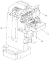
Fig. 1 is a schematic perspective view of the present invention.
Fig. 2 is a second schematic perspective view of the present invention.
Fig. 3 is a third schematic view of a three-dimensional structure of the present invention.
Fig. 4 is a schematic perspective view of the molding member of the present invention.
Fig. 5 is a second schematic perspective view of the molding member of the present invention.
Fig. 6 is a third schematic perspective view of the molding member of the present invention.
Detailed Description
The invention will be further described with reference to the accompanying drawings:
as shown in fig. 1 to 6, the technical solution adopted by the present invention is as follows: a pin bending device for a column winding type electronic component comprises a forming support 61, a forming lifting cylinder 62, a forming linear slide rail 63 and a forming assembly, wherein the forming support 61 is vertically arranged on one side of a rotary table 3; the forming lifting cylinder 62 is arranged on one side of the forming support 61, and the output end of the forming lifting cylinder is connected upwards; the molding linear slide rail 63 is vertically arranged on the side wall of the molding support 61; the molding assembly is slidably connected to the molding linear slide rail 63 and is connected with the output end of the molding lifting cylinder 62, and the molding lifting cylinder 62 drives the molding assembly to move up and down; the forming assembly comprises a forming part 64, a third forming cylinder 65 and a bending forming plate 66, wherein the third forming cylinder 65 is slidably connected to the forming linear slide rail 63, and the output end of the third forming cylinder is arranged downwards; the bending forming plate 66 is connected to the output end of the third forming cylinder 65; the molding member 64 is connected to one side of the third molding cylinder 65; the forming component 64 bends the long pin at the inner side of the component clamped in the jig 4 for the first time by attaching the long pin to the inner side surface of the forming block at one side of the component and bends the long pin for the second time by attaching the long pin to the left side surface of the forming block; after the upper pins of the components are bent for the second time, the bending forming plate 66 moves downwards along the outer side surface of the jig, and the long pins and the short pins of the components are bent for the third time downwards.
The molding member 64 includes a first molding support 641, a first molding cylinder 642, a second molding support 643, a molding guide 644, a second molding cylinder 646, a molding slide 647, a molding pulley 648, a molding lifting seat 649, a molding seat 6410, a first column 6411, a first bending rod 6413, a second column 6415, a swivel 6416, a rod seat 6417 and a second bending rod 6418, wherein the first molding support 641 is connected to a side portion of the third molding cylinder 65, and the first molding cylinder 642 is disposed on the first molding support 641; the second forming strip 643 is slidably connected to the first forming strip 641, is connected to an output end of the first forming cylinder 642, and is driven by the first forming cylinder 642 to move linearly; the second molding cylinder 646 is provided on a second molding stay 643.
The forming guide block 644 is arranged on the top of the second forming support plate 643 and extends to the upper part of the second forming cylinder 646, and the bottom of the forming guide block 644 is provided with a guide arc surface 645.
The forming sliding seat 647 is slidably connected to the second forming cylinder 646 and connected to the output end of the second forming cylinder 646, and a vertical groove is formed in one side of the forming sliding seat 647; the forming lifting seat 649 can be embedded in the vertical groove in a sliding way and is connected with the forming sliding seat 647 through a spring; the forming pulley 648 is rotatably connected to the top of the forming lifting seat 649; in a natural state, the molded lifting seat 649 is pushed up by the upward elastic force of the spring.
The forming seat 6410 is arranged at the bottom of the forming lifting seat 649, and a first column body 6411 and a second column body 6415 are arranged at the lower part of the forming seat 6410 at intervals; the first bending bar 6413 is rotatably connected to the first column 6411; a swing groove 6412 is formed between the first bending bar 6413 and the first column 6411, and a through groove is formed in the middle of the swing groove 6412.
One end of the swivel mount 6416 is rotatably sleeved on the second column body 6415, and the swivel mount 6416 penetrates through the through groove and extends to the other side of the through groove; the rod seat 6417 is disposed at the other end of the rotation seat 6416; the second bending bar 6418 is vertically disposed at a lower portion of the bar seat 6417.
The outer side walls of the bottoms of the first bending rod 6413 and the second bending rod 6418 are respectively provided with an inward-concave circular clamping groove 6414, and the inner diameter of each circular clamping groove 6414 is not smaller than the outer diameter of a pin of the component; during bending, the first bending rod 6413 and the second bending rod 6418 are tightly attached to the long pins of the component, the long pins are embedded into the circular clamping grooves 6414, the first bending rod 6413 and the second bending rod 6418 linearly travel to the left side along the rear side wall of the forming block, so that the long pins are bent for the first time, and the forming pulley 648 slides leftwards along the guide arc 645 and is gradually pressed downwards through the guide arc 645; after the long pin is bent for the first time, the first bending rod 6413 moves linearly to the front side along the left side wall of the forming block, so that the long pin is bent for the second time to the outer side direction; so that the bending forming plate 66 bends the long pins and the short pins downwards for three times.
Further, the utility model designs a through two column pressure pins of bending accomplish the pin automatic bending along the walking of shaping post lateral wall, improved the pin effectively and bent efficiency and the column of the quality of bending around formula electronic components pin bending device. The utility model discloses an electric capacity is accomplishing the braid and cutting the back, and two pins of electric capacity are sharp connection respectively in the both ends of the electric capacity body, and the electric capacity of this kind of shape removes to the standing groove of tool in from taking out the back through feed mechanism, presss from both sides the dress through the tool and fixes the back, and the tool drives electric capacity and removes extremely the utility model discloses the department, the shaping of bending. The utility model discloses a pin bending molding includes the cubic bending, wherein, the object that first bending and second bending are aimed at is the long pin of electric capacity rear side, and the first bending is bent the long pin of electric capacity rear side and is pasted the back lateral wall of shaping piece and bend, and the second bending is bent long pin and is continued to paste the left side wall of shaping piece and bend, makes long pin and electric capacity short pin set up towards the outside the same; and the third bending is to bend the horizontal long pins and the horizontal short pins downwards through the bending forming plate which vertically moves downwards, so that the long pins and the short pins are perpendicular to the capacitor. The utility model discloses a bend and accomplish through the shaping subassembly, wherein, bend twice before the pin and accomplish through the shaping part, bend for the third time of pin and bend through the drive of third shaping cylinder and bend into the shaping board downstream and accomplish the action of bending. The forming part of the utility model comprises a first forming cylinder which is linearly driven along the inner and outer directions and a second forming cylinder which is linearly driven along the left and right directions in the horizontal plane; the utility model uses the forming lifting seat which is arranged in the vertical groove of the forming sliding seat in a sliding way in the vertical direction as a supporting component, a spring is connected between the forming lifting seat and the inner side wall of the vertical groove, and the elastic force of the spring is upwards supported and pushed against the forming lifting seat in the natural state; the lower part of the forming lifting seat is horizontally provided with a forming seat, and the bottom of the forming seat is vertically provided with a first column body and a second column body; the side parts of the first column body and the second column body are respectively and rotatably connected with a first bending rod and a second bending rod, a swing groove is arranged between the first bending rod and the first column body, a through groove is arranged in the middle of the swing groove, a connecting part between the second bending rod and the second column body is positioned and penetrates through the through groove in the swing groove, and the second bending rod can freely move in the swing groove so as to reserve a displacement space; the lower end faces of the first bending rod and the second bending rod of the utility model are provided with annular concave clamping grooves, and the inner diameter of the circular clamping grooves is not less than the outer diameter of the pins; during bending, the first bending rod and the second bending rod approach from the right side of the long pin, so that the long pin slides into the circular clamping groove, the second bending rod contacts the long pin firstly, and the long pin is bent along the rear side wall of the forming block in the process of left linear movement; meanwhile, the first bending rod positioned on the right side of the second bending rod continues to laterally press the long pin at the back in the moving process so as to bend and maintain pressure of the bent long pin, and the bent part of the long pin is prevented from being tilted backwards while the second bending rod bends the long pin. The second bending rod after the first bending is completed moves to the left side of the forming block, and the first bending rod is attached to the rear side wall of the forming block; and during the second bending, the first bending rod and the second bending rod synchronously and linearly move forwards, the second bending rod is in a vacant state, the first bending rod is attached to the left side wall of the forming block to bend the long pins until the long pins extend outwards, and the second bending is completed. After the secondary bending of the long pin is finished, the first bending rod and the second bending rod need to return to a bending initial position so as to perform the next bending action, at the moment, the swinging groove structure of the second bending rod is designed to enable the second bending rod to be limited by the groove wall in the process of primary bending, and the second bending rod can slide along the vacant position of the swinging groove in the returning process; therefore, when the first bending rod and the second bending rod simultaneously move back along the rear side wall of the forming block to the right in a straight line, the left second bending rod can be prevented from laterally pressing the long pin to prevent the left part of the long pin from tilting. Additionally, the utility model discloses a long pin is at the first in-process of bending, and when second shaping cylinder drive shaping slide rectilinear movement left, the shaping pulley that the top of shaping lift seat rotationally set up progressively slides in to the direction cambered surface of the shaping guide block bottom above that to along with the shaping pulley slides left constantly, promote the shaping pulley with the correspondence of direction cambered surface and drive the shaping lift seat and progressively descend, in order to adapt to the pin demand of pushing down when bending.
The embodiments of the present invention are only for describing the specific implementation thereof, and are not limited to the scope of protection thereof. The present invention is not limited to the above embodiments, but can be modified in various ways without departing from the scope of the present invention.
Claims (7)
1. The utility model provides a column winding formula electronic components pin bending device which characterized in that: the device comprises a forming support (61), a forming lifting cylinder (62), a forming linear slide rail (63) and a forming assembly, wherein the forming support (61) is vertically arranged on one side of a turntable (3); the forming lifting cylinder (62) is arranged on one side of the forming support (61), and the output end of the forming lifting cylinder is connected upwards; the forming linear slide rail (63) is vertically arranged on the side wall of the forming support (61); the molding assembly is slidably connected to the molding linear slide rail (63) and is connected with the output end of the molding lifting cylinder (62), and the molding lifting cylinder (62) drives the molding assembly to move up and down; the forming assembly comprises a forming part (64), a third forming cylinder (65) and a bending forming plate (66), wherein the third forming cylinder (65) is connected to the forming linear slide rail (63) in a sliding mode, and the output end of the third forming cylinder is arranged downwards; the bending forming plate (66) is connected to the output end of the third forming cylinder (65); the molding part (64) is connected to one side of the third molding cylinder (65); the forming component (64) bends the long pin at the inner side of the component clamped in the jig (4) for the first time by attaching the long pin to the inner side surface of the forming block at one side of the component and bends the long pin for the second time by attaching the long pin to the left side surface of the forming block; after the upper pins of the components are bent for the second time, the bending forming plate (66) moves downwards along the outer side surface of the jig, and the long pins and the short pins of the components are bent for the third time downwards.
2. The pin bending device for the column-wound electronic component according to claim 1, wherein: the forming part (64) comprises a first forming support plate (641), a first forming air cylinder (642), a second forming support plate (643), a forming guide block (644), a second forming air cylinder (646), a forming sliding seat (647), a forming pulley (648), a forming lifting seat (649), a forming seat (6410), a first column body (6411), a first bending rod (6413), a second column body (6415), a rotating seat (6416), a rod seat (6417) and a second bending rod (6418), wherein the first forming support plate (641) is connected to the side part of the third forming air cylinder (65), and the first forming air cylinder (642) is arranged on the first forming support plate (641); the second forming support plate (643) is connected to the first forming support plate (641) in a sliding manner, is connected with the output end of the first forming cylinder (642), and is driven by the first forming cylinder (642) to move linearly; the second forming cylinder (646) is provided on a second forming stay (643).
3. The pin bending device for the column-wound electronic component according to claim 2, wherein: the forming guide block (644) is arranged at the top of the second forming support plate (643) and extends to the upper side of the second forming cylinder (646), and a guide arc surface (645) is arranged at the bottom of the forming guide block (644).
4. The pin bending device for the column-wound electronic component according to claim 3, wherein: the forming sliding seat (647) is slidably connected to the second forming cylinder (646) and is connected with the output end of the second forming cylinder (646), and a vertical groove is formed in one side of the forming sliding seat (647); the forming lifting seat (649) can be slidably embedded in the vertical groove and is connected with the forming sliding seat (647) through a spring; the forming pulley (648) is rotatably connected to the top of the forming lifting seat (649); in a natural state, the forming lifting seat (649) is pushed upwards by the upward elastic force of a spring.
5. The pin bending device for the column-wound electronic component according to claim 4, wherein: the forming seat (6410) is arranged at the bottom of the forming lifting seat (649), and a first column body (6411) and a second column body (6415) are arranged at the lower part of the forming seat (6410) at intervals; the first bending rod (6413) is rotatably connected to the first column (6411); a swing groove (6412) is arranged between the first bending rod (6413) and the first column body (6411), and a through groove is arranged in the middle of the swing groove (6412).
6. The pin bending device for the column-wound electronic component according to claim 5, wherein: one end of the swivel seat (6416) is rotatably sleeved on the second column body (6415), and the swivel seat (6416) penetrates through the through groove and extends to the other side of the through groove; the rod seat (6417) is arranged at the other end of the rotating seat (6416); the second bending bar (6418) is vertically disposed at the lower portion of the bar seat (6417).
7. The pin bending device for the column-wound electronic component according to claim 6, wherein: the outer side walls of the bottoms of the first bending rod (6413) and the second bending rod (6418) are respectively provided with an inward-concave circular clamping groove (6414), and the inner diameter of each circular clamping groove (6414) is not less than the outer diameter of a pin of the component; during bending, the first bending rod (6413) and the second bending rod (6418) are tightly attached to the long pin of the component, the long pin is embedded into the circular clamping groove (6414), the first bending rod (6413) and the second bending rod (6418) linearly travel to the left side along the rear side wall of the forming block, so that the long pin is bent for the first time, and the forming pulley (648) slides leftwards along the guide arc surface (645) and is gradually pressed downwards through the guide arc surface (645); after the long pin is bent for the first time, the first bending rod (6413) moves to the front side linearly along the left side wall of the forming block, so that the long pin is bent for the second time to the outer side direction; so that the bending forming plate (66) bends the long pins and the short pins downwards for three times.
Priority Applications (1)
| Application Number | Priority Date | Filing Date | Title |
|---|---|---|---|
| CN201920783602.7U CN210547620U (en) | 2019-05-28 | 2019-05-28 | Column winding type electronic component pin bending device |
Applications Claiming Priority (1)
| Application Number | Priority Date | Filing Date | Title |
|---|---|---|---|
| CN201920783602.7U CN210547620U (en) | 2019-05-28 | 2019-05-28 | Column winding type electronic component pin bending device |
Publications (1)
| Publication Number | Publication Date |
|---|---|
| CN210547620U true CN210547620U (en) | 2020-05-19 |
Family
ID=70669796
Family Applications (1)
| Application Number | Title | Priority Date | Filing Date |
|---|---|---|---|
| CN201920783602.7U Active CN210547620U (en) | 2019-05-28 | 2019-05-28 | Column winding type electronic component pin bending device |
Country Status (1)
| Country | Link |
|---|---|
| CN (1) | CN210547620U (en) |
Cited By (3)
| Publication number | Priority date | Publication date | Assignee | Title |
|---|---|---|---|---|
| CN111760952A (en) * | 2020-06-28 | 2020-10-13 | 博众精工科技股份有限公司 | Pack battery mechanism of bending |
| CN112714607A (en) * | 2020-12-25 | 2021-04-27 | 东莞市冠佳电子设备有限公司 | Multifunctional pin bending mechanism |
| CN114309345A (en) * | 2021-12-31 | 2022-04-12 | 江苏奥力威传感高科股份有限公司 | Capacitor pin bending and shearing equipment |
-
2019
- 2019-05-28 CN CN201920783602.7U patent/CN210547620U/en active Active
Cited By (3)
| Publication number | Priority date | Publication date | Assignee | Title |
|---|---|---|---|---|
| CN111760952A (en) * | 2020-06-28 | 2020-10-13 | 博众精工科技股份有限公司 | Pack battery mechanism of bending |
| CN112714607A (en) * | 2020-12-25 | 2021-04-27 | 东莞市冠佳电子设备有限公司 | Multifunctional pin bending mechanism |
| CN114309345A (en) * | 2021-12-31 | 2022-04-12 | 江苏奥力威传感高科股份有限公司 | Capacitor pin bending and shearing equipment |
Similar Documents
| Publication | Publication Date | Title |
|---|---|---|
| CN110087447B (en) | Automatic cutting, forming and pin cutting device for braid components and processing technology thereof | |
| CN210547620U (en) | Column winding type electronic component pin bending device | |
| CN210547671U (en) | Automatic forming pin shearing device for electronic components | |
| CN104742630A (en) | Automatic embossing equipment | |
| CN210491562U (en) | Automatic cutting, forming and pin cutting device for braid components | |
| CN115780675A (en) | Hairpin motor stator flat copper wire 2D former | |
| CN204622049U (en) | Multistation embossing manipulator | |
| CN106424373A (en) | Stamping die for automatic feeding in die | |
| CN117438824A (en) | Punching press formula copper pipe contact pin and processingequipment thereof | |
| CN208724214U (en) | A kind of sound film and voice coil gluing tool | |
| CN213944679U (en) | Bending equipment for pins of electronic devices | |
| CN210476656U (en) | Electronic components presss from both sides dress tool and tool device that opens and shuts | |
| CN212442721U (en) | Automatic adjusting locking bending die | |
| CN208614193U (en) | Copper wire for intelligent plug assembling equipment collapses correction positioning device | |
| CN204673619U (en) | Embossing manipulator mechanism | |
| CN108581501B (en) | Integrated wall plate special fastening automatic processing device | |
| CN211542116U (en) | Novel terminal insert mould die cavity supplementary device | |
| CN210937956U (en) | Automatic multi-station chuck replacing device | |
| CN211758182U (en) | Device for processing current thermal protector wire | |
| CN208843491U (en) | It is a kind of for manufacturing the automatic copper-wire feeding device of wire rod | |
| CN210479124U (en) | Automatic change oblique rubber coating device | |
| CN207577230U (en) | A kind of Flag-shaped mould | |
| CN204622969U (en) | Multifunctional embossing machinery hand | |
| CN219833287U (en) | Terminal riveting machine | |
| CN210306586U (en) | Automatic needle seat assembling machine |
Legal Events
| Date | Code | Title | Description |
|---|---|---|---|
| GR01 | Patent grant | ||
| GR01 | Patent grant |