CN210524750U - Mirror surface polishing machine - Google Patents
Mirror surface polishing machine Download PDFInfo
- Publication number
- CN210524750U CN210524750U CN201921504010.3U CN201921504010U CN210524750U CN 210524750 U CN210524750 U CN 210524750U CN 201921504010 U CN201921504010 U CN 201921504010U CN 210524750 U CN210524750 U CN 210524750U
- Authority
- CN
- China
- Prior art keywords
- guide rail
- roller
- thimble
- assembly
- grinding
- Prior art date
- Legal status (The legal status is an assumption and is not a legal conclusion. Google has not performed a legal analysis and makes no representation as to the accuracy of the status listed.)
- Active
Links
Images


Abstract
The utility model relates to the technical field of roller piece processing, and discloses a mirror surface polishing machine, which is characterized in that the mirror surface polishing machine comprises a workbench, wherein a first guide rail and a second guide rail are arranged on the workbench, a fixed thimble assembly and a movable thimble assembly are arranged on the first guide rail, a mounting seat is arranged on the second guide rail, and a coarse grinding assembly and a fine grinding assembly are arranged on the mounting seat; the fixed thimble assembly comprises a first fixed base and a left thimble, and a first driving motor is arranged below the workbench; the movable thimble assembly comprises a second fixed base and a right thimble, and one side of the workbench is provided with a second driving motor; the rough grinding assembly and the accurate grinding assembly comprise a support frame and a driving motor, one side of the support frame is rotatably connected with a rotating shaft, one end of the rotating shaft of the rough grinding assembly is provided with a rough grinding polishing disc, one end of the rotating shaft of the accurate grinding assembly is provided with an accurate grinding polishing disc, and the support frame is connected with a feeding mechanism. The utility model has the advantages of save roller spare surface machining cost, improve the mirror surface effect.
Description
Technical Field
The utility model relates to a technical field of roller spare processing, in particular to mirror surface polishing machine.
Background
The roller is a part widely applied to various transmission conveying systems of printing, papermaking, packaging machinery and the like, and in the actual manufacturing process, the surface of the roller needs to be treated after the roller is machined by a lathe, so that the roughness of the surface of the roller can reach the application standard.
In the prior art, a cylindrical grinding machine, a grinding machine and a cloth wheel polishing machine are usually used for processing a roller, the roller is firstly roughly ground on the cylindrical grinding machine, and then is finely ground by the grinding machine or the cloth wheel polishing machine, so that the roughness of the surface of the roller reaches the application standard. In the course of rough grinding and accurate grinding, the medium of saponification liquid, cooling water, polishing paste, kerosene and the like is needed to achieve the lubricating and cooling effects.
However, in the actual processing process, a plurality of devices need to be utilized to work in a matching manner, which undoubtedly increases the purchase cost of enterprises and the later-stage power and maintenance cost; in addition, the roll member to be processed needs to be repeatedly dismounted and mounted on a plurality of devices, which undoubtedly increases the labor load of workers and increases the labor cost of enterprises.
SUMMERY OF THE UTILITY MODEL
The utility model aims at providing a mirror surface polishing machine has the advantage of saving roller spare surface machining cost, improving roller mirror surface effect.
The above technical purpose of the present invention can be achieved by the following technical solutions:
a mirror surface polishing machine comprises a workbench, wherein a first guide rail and a second guide rail which are parallel to each other are arranged on the workbench, a fixed ejector pin assembly and a movable ejector pin assembly are arranged on the first guide rail, an installation seat is arranged on the second guide rail, a control motor for driving the installation seat to slide along the second guide rail is arranged on one side of the second guide rail, and a coarse grinding assembly and a fine grinding assembly are arranged on the installation seat;
the fixed thimble assembly comprises a first fixed base and a left thimble, the first fixed base is fixedly connected to the first guide rail, the left thimble is rotatably connected to the first fixed base, and a first driving motor for driving the left thimble to rotate is arranged below the workbench;
the movable thimble assembly comprises a second fixed base and a right thimble, the second fixed base is connected with the first guide rail in a sliding manner, the right thimble and the left thimble are coaxially arranged, and one side of the workbench is provided with a second driving motor for driving the second fixed base to slide along the first guide rail;
the corase grind subassembly and the correct grinding subassembly all include support frame and driving motor three, one side that the support frame is close to the guided way one is rotated and is connected with the axis of rotation, driving motor three is used for driving the axis of rotation and rotates, the one end of the axis of rotation of corase grind subassembly is equipped with the corase grind and throws the dish, the one end of the axis of rotation of correct grinding subassembly is equipped with the correct grinding and throws the dish, the support frame slides and connects on the mount pad, be connected with on the support frame and be used for driving the corase grind and throw.
By adopting the technical scheme, when the surface of the roller piece is machined, the roller piece is clamped between the left thimble and the right thimble, and is driven by the first driving motor to rotate. Then, start the feed mechanism on the corase grind subassembly, this feed mechanism drive corase grind subassembly moves towards the roller, at the in-process that moves towards the roller, driving motor three drive corase grind throwing disc rotates, when the corase grind throwing disc is contradicted on the roller, the corase grind between corase grind throwing disc and the roller is realized the corase grind to the roller, after the corase grind processing is accomplished, reverse operation corase grind feed mechanism on the subassembly for the corase grind throwing disc leaves the roller. Then, start the feed mechanism on the correct grinding subassembly, this feed mechanism drive correct grinding subassembly moves towards roller spare, at the in-process that moves towards roller spare, driving motor three drives the correct grinding and throws the dish and rotate, when the correct grinding and throw the dish and contradict on roller spare, the mutual friction between correct grinding and throw dish and the roller spare realizes the correct grinding to roller spare to make the mirror surface effect of roller surface obtain promoting, after the finish grinding processing of roller surface was accomplished, the feed mechanism on the reverse operation correct grinding subassembly, make the correct grinding and throw the dish and leave roller spare.
The utility model has the advantages that when the surface of the roller is processed, the rough grinding and the accurate grinding of the roller are finished on one device, compared with the common cooperation of a plurality of devices in the prior art, the purchasing cost of enterprises and the later-stage electric power and maintenance cost are reduced; in addition, the roller piece is only required to be installed and detached once in the whole machining process, the labor load of workers is reduced, the labor cost is reduced, and therefore the effect of greatly saving the surface machining cost of the roller piece is achieved.
Simultaneously, at the in-process of processing to the roller spare, the processing on roller surface goes on same equipment, therefore the corase grind with the correct grinding is gone on at same time stage, need not to cool off and lubricate, consequently need not to use medium such as saponification liquid, cooling water, polishing cream, kerosene, this has solved the problem that pollutes greatly among the current roller processing technology, pollutes difficult clearance undoubtedly, has improved environmental protection effect greatly.
In addition, in the treatment process after grinding, such as copper plating, the roller achieves the mirror surface effect under the coordination of rough grinding and fine grinding, so that the surface of the roller is less sunken, the thickness required by copper plating is thinner compared with the prior art, and the raw material cost of enterprises is greatly reduced in batch production.
Furthermore, a dust collection cover is respectively arranged on one side of the rough grinding polishing disc and one side of the fine grinding polishing disc, which are far away from the first guide rail, the bottom of the dust collection cover is communicated with a dust collection pipe, a dust collection fan is arranged on the ground, an air inlet of the dust collection fan is communicated with the dust collection pipe, and an air outlet of the dust collection fan is communicated with a dust collection cloth bag.
Through adopting above-mentioned technical scheme, dust absorption fan can be with the automatic dust removal cloth bag of inhaling of the sediment bits that produce among the grinding and polishing process to the raising of operational environment dust has been reduced. Meanwhile, the slag chips are metal waste materials, and are not mixed with media such as saponification liquid, cooling water, polishing paste, kerosene and the like, so that the slag chips can be directly recycled, and compared with the prior art, the treatment cost of the later stage of the slag chips is greatly reduced.
Furthermore, the end face of the rotating shaft is fixedly connected with an installation screw, and a locking nut is connected to the installation screw in a threaded manner.
Through adopting above-mentioned technical scheme, installation screw rod and lock nut's cooperation has improved the convenience when the corase grind is thrown dish and the change is thrown to the finish grinding, and the staff can select suitable throwing dish according to the material of roller and the roughness precision on roller surface.
Furthermore, one side of workstation is equipped with PLC control system, control motor electric connection is in PLC control system, one side that the mount pad is towards the guided way one is equipped with the photoelectric sensor group that is used for responding to the roller spare both ends position of waiting to process, photoelectric sensor group electric connection is in PLC control system.
Through adopting above-mentioned technical scheme, PLC control system has improved the utility model discloses an degree of automation to further alleviateed staff's work load, improved work efficiency. In addition, the photoelectric sensor group can sense the positions of the two ends of the roller, so that the motor is controlled to drive the coarse grinding assembly or the fine grinding assembly to reciprocate between the two ends of the roller through a PLC control system command, and the automation degree of grinding and polishing is improved.
Furthermore, a current sensor is arranged on the support frame and electrically connected to the PLC control system.
Through adopting above-mentioned technical scheme, when the roller spare was contradicted to rough grinding polishing disk or accurate grinding polishing disk, along with the increase of the pressure of contradicting, the frictional force increase between rough grinding polishing disk or accurate grinding polishing disk and the roller spare of waiting to process, the increase of frictional force impeld three required electric currents of driving motor to increase gradually, and the electric current passes through current sensor's detection, shows at PLC operation platform. Therefore, the operator can determine the pressure exerted on the roller by the rough grinding polishing disk or the accurate polishing disk through the current detected by the current sensor, so as to determine the friction force between the rough grinding polishing disk or the accurate polishing disk and the roller, and ensure the final grinding and polishing effect of the roller.
Furthermore, be equipped with distance sensor on the support frame, distance sensor's the directional axis of left thimble and right thimble of transmitting end, distance sensor electric connection is in PLC control system.
By adopting the technical scheme, on one hand, the distance sensor can measure the diameter of the roller; on the other hand, the distance between the distance sensor and the roller can be transmitted to the PLC control system, and when the distance between the distance sensor and the roller is gradually reduced, the PLC control system can control the current of the feeding motor, so that the feeding speed of the rough grinding assembly or the fine grinding assembly is reduced.
Furthermore, be equipped with the sound-proof housing on the workstation, the sound-proof housing is close to one side of guided way one and is opened there is the installing port, it has the shielding plate that is used for the shutoff installing port to slide on the sound-proof housing.
Through adopting above-mentioned technical scheme, the sound-proof housing can reduce the utility model discloses the noise that produces in the working process has consequently alleviateed the utility model discloses a noise pollution has further improved environmental protection effect.
Furthermore, the second driving motor is electrically connected with a foot switch.
By adopting the technical scheme, when the worker embraces the roller between the left thimble and the right thimble, the worker can start the second driving motor through the sole, and the second driving motor drives the right thimble to move towards the left thimble, so as to tightly push the roller. The arrangement of the foot switch improves the convenience of operation of workers, only one worker is needed in the process of installing the roller, and the labor cost of work is reduced.
To sum up, the utility model discloses following beneficial effect has:
1. the rough grinding and the accurate grinding of the roller are finished on the same equipment, so that the method has the advantage of greatly saving the surface processing cost of the roller;
2. in the processing process of the roller, media such as saponification liquid, cooling water, polishing paste, kerosene and the like are not needed, the problems of high pollution and difficult cleaning in the existing roller processing technology are solved, and the environmental protection effect is greatly improved;
3. the roller is in a mirror surface effect after grinding, and in a later treatment process, such as copper plating, due to the fact that the surface of the roller is small in depression, compared with the prior art, the thickness required by copper plating is thinner, and the raw material cost of an enterprise is greatly reduced during batch processing;
4. the dust collection fan can automatically suck the slag generated in the grinding and polishing process into the dust removal cloth bag, so that the dust in the working environment is reduced, and the environment-friendly effect is improved;
5. PLC control system has improved the utility model discloses an degree of automation to further alleviateed staff's work load, improved work efficiency.
Drawings
Fig. 1 is a schematic structural diagram for embodying the present invention;
FIG. 2 is a schematic diagram of a configuration for embodying a PLC control system;
FIG. 3 is a schematic view of an internal structure for embodying the present invention;
fig. 4 is a schematic structural view for embodying the rough grinding assembly and the finish grinding assembly;
FIG. 5 is a schematic structural diagram for embodying a first driving screw rod;
fig. 6 is a schematic structural view for embodying the feed mechanism.
In the figure, 1, a workbench; 11. a sound-proof housing; 111. an unloading port; 112. a moving guide rail; 113. a shielding plate; 2. a first guide rail; 21. a sliding base; 211. a guide slide rail; 22. protecting the upper shell; 3. a second guide rail; 4. fixing the thimble assembly; 41. a first fixed base; 42. a left thimble; 421. a driven sprocket; 43. driving a motor I; 431. a drive sprocket; 44. a drive chain; 5. moving the thimble assembly; 51. a second fixed base; 511. a first connecting plate; 52. a right thimble; 53. driving a first screw rod; 531. a first bearing seat; 54. a second driving motor; 541. a foot switch; 6. a mounting seat; 61. controlling the motor; 62. a second connecting plate; 63. a second driving screw rod; 64. a second bearing seat; 65. a sliding guide groove; 66. a support block; 67. an edge plate; 7. a rough grinding assembly; 71. a support frame; 711. sliding the rail; 712. a connecting frame; 72. driving a motor III; 721. a driving pulley; 73. a rotating shaft; 731. installing a screw rod; 7311. a lock nut; 732. a driven pulley; 74. a third bearing seat; 75. roughly grinding and polishing a disc; 76. a drive belt; 77. a feed mechanism; 771. a feed motor; 772. a feed screw; 8. a finish grinding assembly; 81. finely grinding the polishing disc; 9. a PLC control system; 91. a current sensor; 92. a group of photosensors; 93. a distance sensor; 94. a PLC operation platform; 10. a dust collection cover; 101. a let position port; 102. a dust collection pipe; 103. a dust collection fan; 104. a dust collection header pipe; 105. a dust removal cloth bag.
Detailed Description
The present invention will be described in further detail with reference to the accompanying drawings.
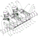
Example (b): a mirror surface polishing machine, refer to fig. 1, comprises a workbench 1, and a first guide rail 2 and a second guide rail 3 which are parallel to each other are arranged on the workbench 1. And a fixed ejector pin assembly 4 and a movable ejector pin assembly 5 are arranged on the first guide rail 2, a mounting seat 6 is arranged on the second guide rail 3, a control motor 61 for driving the mounting seat 6 to slide along the second guide rail 3 is arranged on one side of the second guide rail 3, and a coarse grinding assembly 7 and a fine grinding assembly 8 are arranged on the mounting seat 6.
Referring to fig. 5, the first guide rail 2 and the second guide rail 3 have the same structure and each include a sliding base 21 and a protective upper shell 22. The base 21 that slides is fixed connection on workstation 1, and protection epitheca 22 fixed connection has the interval between the two on the base 21 that slides. The sliding base 21 is fixedly connected with two guide slide rails 211, and the two guide slide rails 211 are arranged side by side along the width direction of the sliding base 21.
Referring to fig. 3, the fixed needle assembly 4 includes a first fixed base 41 and a left needle 42. The first fixed base 41 is fixedly connected to the sliding base 21 and the protective upper shell 22. The left thimble 42 is rotatably connected to the first fixing base 41 through a bearing, and one end of the left thimble 42 extending out of the first fixing base 41 is conical.
Referring to fig. 3, one end of the left thimble 42 extending into the first fixed base 41 is fixedly sleeved with a driven sprocket 421, a first driving motor 43 is connected to the lower portion of the workbench 1 through a bolt, an output shaft of the first driving motor 43 is fixedly sleeved with a driving sprocket 431, and a transmission chain 44 is engaged between the driving sprocket 431 and the driven sprocket 421. When the first driving motor 43 is started, the left thimble 42 is driven by the transmission chain 44 to rotate.
Referring to fig. 3, the movable needle assembly 5 includes a second fixed base 51 and a right needle 52. The right thimble 52 and the left thimble 42 are disposed opposite to each other along the length direction of the first fixing base, and are coaxial. The second fixed base 51 is buckled on the upper protection shell 22 in a U shape, a first connecting plate 511 is fixedly connected between the bottoms of the second fixed base 51, and the first connecting plate 511 bypasses the sliding base 21 and is connected to the guide sliding rail 211 in a sliding manner.
Referring to fig. 3 and 5, a first driving screw 53 is disposed between the guide rails 211 at both sides, and the first driving screw 53 passes through and is threadedly coupled to a first connection plate 511. Two ends of the first driving screw 53 are respectively sleeved with a first bearing seat 531, and the first bearing seats 531 are fixedly connected to the sliding base 21. One side of the working table 1 is connected with a second driving motor 54 through a bolt, the second driving motor 54 is coaxially connected with the first driving screw 53, and the second driving motor 54 is electrically connected with a foot switch 541 (refer to fig. 1).
Referring to fig. 1, when a roller is machined, a worker firstly lifts the roller between the left thimble 42 and the right thimble 52, then the second driving motor 54 is started through the foot switch 541, the second driving motor 54 drives the first driving screw 53 to rotate, and the screw thread fit between the first driving screw 53 and the first connecting plate 511 urges the second fixing base 51 to move towards the left thimble 42, so that the roller to be machined is abutted between the left thimble 42 and the right thimble 52.
Referring to fig. 6, the mounting seat 6 is U-shaped and fastened to the protective upper shell 22 of the second guide rail 3, a second connecting plate 62 is fixedly connected between the bottoms of the mounting seat 6, and the second connecting plate 62 bypasses the sliding base 21 and is connected to the guide rail 211 in a sliding manner. And a second driving screw rod 63 is arranged between the two guide slide rails 211 of the second guide rail 3, and the second driving screw rod 63 penetrates through and is in threaded connection with the second connecting plate 62. Two ends of the second driving screw 63 are respectively sleeved with a second bearing seat 64, and the second bearing seats 64 are fixedly connected to the sliding base 21 of the second guide rail 3.
Referring to fig. 1 and 6, a control motor 61 is connected to one side of the table 1 by bolts, and an output shaft of the control motor 61 is coaxially connected to a second driving screw 63. In the process of processing the roller, the control motor 61 drives the second driving screw rod 63 to rotate, the screw thread fit between the second driving screw rod 63 and the second connecting plate 62 enables the mounting seat 6 to move along the length direction of the second guide rail 3, and in the moving process, the mounting seat 6 drives the coarse grinding assembly 7 and the fine grinding assembly 8 to polish the surface of the roller, so that the roller is processed.
Referring to fig. 4, the rough grinding assembly 7 and the fine grinding assembly 8 are symmetrically disposed on the mounting base 6 along the length direction of the guide rail two 3, and both include a support frame 71 and a driving motor three 72. A rotating shaft 73 is rotatably connected to one side of the supporting frame 71 close to the first guide rail 2, and the rotating shaft 73 is parallel to a connecting line between the left thimble 42 and the right thimble 52. In order to improve the rotation fluency of the rotating shaft 73, two bearing blocks three 74 are sleeved on the rotating shaft 73, and the bearing blocks three 74 are fixedly connected to the supporting frame 71.
Referring to fig. 4, one end of the rotating shaft 73 of the rough grinding assembly 7 is provided with a rough grinding polishing disc 75, one end of the rotating shaft 73 of the fine grinding assembly 8 is provided with a fine grinding polishing disc 81, and the rough grinding polishing disc 75 and the fine grinding polishing disc 81 are perpendicular to the rotating shaft 73. An end surface of the rotating shaft 73 is fixedly connected with a mounting screw 731, and a locking nut 7311 is connected to the mounting screw 731 in a threaded manner. The fit between the locking nut 7311 and the mounting screw 731 enables the rough grinding polishing disc 75 and the accurate grinding polishing disc 81 to be detached, and in the actual working process, workers can replace the rough grinding polishing disc 75 and the accurate grinding polishing disc 81 according to the material of the roller piece and the abrasion condition of the rough grinding polishing disc 75 and the accurate grinding polishing disc 81.
Referring to fig. 4, a driven pulley 732 is fixedly secured to an end of the rotating shaft 73 remote from the rough grinding polishing disk 75 or the finish grinding polishing disk 81, the driving motor 72 is connected to the supporting frame 71 by bolts, a driving pulley 721 is fixedly secured to an output shaft thereof, and a transmission belt 76 is connected between the driven pulley 732 and the driving pulley 721. The rotating shaft 73 is driven by the driving motor 72 to rotate in a belt transmission manner, and the first rotating shaft 73 drives the rough grinding polishing disc 75 or the fine grinding polishing disc 81 to rotate in the rotating process.
Referring to fig. 6, a sliding rail 711 is fixedly connected to a lower surface of the supporting frame 71, and a longitudinal direction of the sliding rail 711 is perpendicular to a longitudinal direction of the first guide rail 2. A sliding guide groove 65 is fixedly connected to the upper surface of the mounting seat 6, and the sliding rail 711 slides in the sliding guide groove 65.
Referring to fig. 6, a feeding mechanism 77 is connected to the supporting frame 71, the feeding mechanism 77 includes a feeding motor 771 and a feeding screw 772, and the feeding screw 772 is located below the supporting frame 71. A supporting block 66 is fixedly connected to the upper surface of the mounting base 6, a feed screw 772 penetrates through and is in threaded connection with the supporting block 66, a feed motor 771 is connected to one side of the supporting frame 71, and the output shaft of the feed motor 771 is coaxially connected to the feed screw.
Referring to fig. 6, after the roller is fixed between the left thimble 42 and the right thimble 52, the worker first starts the feeding motor 771 of the rough grinding assembly 7, the feeding motor 771 slides towards the first guide rail 2 through the screw thread fit between the feeding screw 772 and the supporting block 66, and in the sliding process, the supporting frame 71 drives the rough grinding throwing disc 75 to move towards the surface of the roller to be processed. Meanwhile, the first driving motor 43 drives the roller to rotate, and the third driving motor 72 drives the rough grinding polishing disk 75 to rotate. When the rough grinding polishing disk 75 abuts against the surface of the roller, the relative friction between the rough grinding polishing disk 75 and the roller causes the surface of the roller to be roughly ground.
Referring to fig. 4, after the rough grinding process is completed, the feed motor 771 on the rough grinding assembly 7 is reversed, and the reversed feed motor 771 urges the rough grinding polishing disk 75 gradually away from the roller member to be processed until the rough grinding assembly 7 is restored to the initial position. Next, the worker starts the feed motor 771 on the fine grinding assembly 8, so that the fine grinding polishing disc 81 performs fine grinding on the roll member, thereby achieving a mirror surface effect on the surface of the roll member.
Compare in traditional roller spare polishing mode, the utility model discloses when polishing to roller spare, need not to use the material of saponification liquid, cooling water, polishing paste, kerosene, consequently reduced the environmental problem that above-mentioned material brought in very big degree, improved environmental protection effect in very big degree.
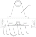
Referring to fig. 6, during the grinding process of the roller, the pressure applied to the roller has a crucial influence on the final grinding effect. Therefore, in order to control the pressing force of the fine grinding polishing disk 81 and the rough grinding polishing disk 75 against the roller members, a current sensor 91 is provided on the support frame 71, and a wire for supplying power to the drive motor 72 passes through the current sensor 91.
Referring to fig. 6, a PLC control system 9 (see fig. 2) is provided at one side of the table 1, the current sensor 91 and the feed motor 771 are electrically connected to the PLC control system 9, respectively, and a PLC operation platform 94 (see fig. 1) is connected to one side of the table 1. When the rough grinding polishing disk 75 or the fine grinding polishing disk 81 collides with the roller, the friction force between the rough grinding polishing disk 75 or the fine grinding polishing disk 81 and the roller to be processed is increased along with the increase of the colliding pressure, so that the current required for driving the motor three 72 is gradually increased, and the current is detected by the current sensor 91 and displayed on the PLC operation platform 94.
In the working process, a worker can set the current preset value of the feeding motor 771 in the PLC control system 9 according to the processing requirement of the roller, and when the rough grinding polishing disc 75 or the fine grinding polishing disc 81 is abutted to the surface of the roller and the current is kept at the set current preset value, the feeding motor 771 does not convey the rough grinding assembly 7 and the fine grinding assembly 8, so that a good polishing effect is achieved.
Referring to fig. 4, the control motor 61 is electrically connected to the PLC control system 9, one side of the mounting base 6 facing the first guide rail 2 is fixedly connected with an edge plate 67, a photoelectric sensor group 92 penetrates through the edge plate 67, and the photoelectric sensor group 92 is electrically connected to the PLC control system 9.
Referring to fig. 4, photoelectric sensor group 92 is used for responding to the position of waiting to process roller spare both ends to utilize PLC control system 9 to control the positive and negative rotation of control motor 61, make this mount pad 6 can carry out reciprocating motion between the both ends of roller spare, improved the utility model discloses a degree of automation.
Referring to fig. 4, a connecting frame 712 is fixedly connected to the supporting frame 71, a distance sensor 93 is disposed at a top end of the connecting frame 712, an emitting end of the distance sensor 93 points to an axis of the left thimble 42 and the right thimble 52, and the distance sensor 93 is electrically connected to the PLC control system 9.
Referring to fig. 4, the distance sensor 93 can measure the diameter of the roller on the one hand, the distance from the axis between the left thimble 42 and the right thimble 52 is an initial value a, the distance from the surface of the roller is a measured value B, and the diameter of the roller is 2 times the absolute value of the difference between a and B; on the other hand, the distance sensor 93 can transmit the distance between it and the roll member to the PLC control system 9, and when the distance between the distance sensor 93 and the roll member is gradually decreased, the PLC control system 9 can control the current of the feeding motor 771, thereby slowing down the feeding speed of the rough grinding assembly 7 or the fine grinding assembly 8.
Referring to fig. 4, dust hoods 10 are respectively arranged on the sides of the rough grinding polishing disk 75 and the fine grinding polishing disk 81, which are far away from the guide rail one 2, the dust hoods 10 are fixedly connected to the support frame 71, and an escape opening 101 is formed in one side of each dust hood 10, which faces the roller. The bottom of the dust hood 10 is communicated with a dust suction pipe 102, a dust suction fan 103 is arranged on the ground, an air inlet of the dust suction fan 103 is communicated with a dust suction main pipe 104, the dust suction pipe 102 is communicated with the dust suction main pipe 104, and an air outlet of the dust suction fan 103 is communicated with a dust removal cloth bag 105.
Referring to fig. 4, in the polishing process of the rough grinding polishing disk 75 or the fine grinding polishing disk 81, the dust absorption fan 103 can absorb the slag generated in the polishing process into the dust removal cloth bag 105, so that the cleanliness of the working environment is improved, and the environment-friendly effect is achieved.
Referring to fig. 1, a sound-proof cover 11 is provided on a table 1, and the sound-proof cover 11 is fixedly attached to the table 1. One side of the sound-proof housing 11 close to the first guide rail 2 is provided with an unloading opening 111, the outer surface of the sound-proof housing 11 and the upper side and the lower side of the unloading opening 111 are respectively and fixedly connected with a movable guide rail 112, and a shielding plate 113 for plugging the unloading opening 111 is connected between the upper movable guide rail 112 and the lower movable guide rail 112 in a sliding manner.
Referring to fig. 1, the loading/unloading opening 111 is used for loading/unloading the roller member, and the shielding plate 113 seals the loading/unloading opening 111 during the polishing process, and the soundproof cover 11 is in a closed state. The closed soundproof cover 11 has an effect of reducing noise, and can reduce noise generated in a working environment, thereby reducing noise pollution.
The specific implementation process comprises the following steps:
firstly, fixing a roller piece:
1. opening the unloading opening 111, then placing the roller to be processed between the left thimble 42 and the right thimble 52, starting the first driving motor 43 at the moment, and clamping the roller to be processed between the left thimble 42 and the right thimble 52 through the jacking of the right thimble 52;
2. starting the control motor 61, and driving the mounting seat 6 to move by using the control motor 61 until the rough grinding assembly 7 is opposite to one end of the roller to be processed;
II, rough grinding of the roller:
1. starting a feed motor 771 on the rough grinding assembly 7, wherein a distance sensor 93 is used for sensing the distance between the rough grinding polishing disk 75 and the roller, and the rotation speed of the feed motor 771 is gradually reduced along with the reduction of the distance, so that the speed of the rough grinding assembly 7 reaching the roller is reduced;
2. in the process that the rough grinding assembly 7 approaches the roller, the first driving assembly drives the left thimble 42 to rotate, and the left thimble 42 drives the roller to rotate;
3. and starting the third driving motor 72, driving the third rough grinding polishing disk 75 to rotate by the third driving motor 72, and polishing the surface of the roller by the rough grinding polishing disk 75 when the rough grinding polishing disk 75 is attached to the roller. In the polishing process, the current sensor 91 outputs the current of the driving motor III 72 to the PLC control system 9, and when the current is kept at the set current preset value, the feeding motor 771 does not convey the rough grinding assembly 7 any more, so that a good polishing effect is achieved;
4. in the process that the rough grinding polishing disc 75 rubs the roller, the control motor 61 drives the mounting seat 6 to move along the length direction of the roller, and the photoelectric sensing assembly is used for sensing the positions of two ends of the roller, so that the rough grinding polishing disc 75 performs reciprocating polishing movement on the roller;
5. after the rough grinding polishing disk 75 finishes polishing, reversing the feeding motor 771 on the rough grinding assembly 7 to enable the rough grinding polishing disk 75 to be separated from the surface of the roller;
thirdly, fine grinding roller:
1. the feed motor 771 of the refining assembly 8 is started, the feed motor 771 drives the refining polishing disc 81 to move towards the roller member, and when the refining polishing disc 81 is attached to the roller member, the refining polishing disc 81 polishes the surface of the roller member. In the polishing process, the current sensor 91 outputs the current of the driving motor III 72 to the PLC control system 9, and when the current is kept at the set current preset value, the feeding motor 771 does not convey the rough grinding assembly 7 any more, so that a good polishing effect is achieved;
2. in the process that the fine grinding polishing disc 81 rubs the roller, the control motor 61 drives the mounting seat 6 to move along the length direction of the roller, and the photoelectric sensing assembly is used for sensing the positions of two ends of the roller, so that the fine grinding polishing disc 81 performs reciprocating polishing motion on the roller;
3. after finishing the polishing of the fine grinding polishing disc 81, the feed motor 771 on the fine grinding assembly 8 is reversed, so that the fine grinding polishing disc 81 is separated from the surface of the roller, thereby finishing the fine grinding processing of the roller and enabling the surface of the roller to present a mirror surface effect.
The present embodiment is only for explaining the present invention, and it is not limited to the present invention, and those skilled in the art can make modifications to the present embodiment without inventive contribution as required after reading the present specification, but all of them are protected by patent laws within the scope of the claims of the present invention.
Claims (8)
1. The mirror polishing machine is characterized in that: the device comprises a workbench (1), wherein a first guide rail (2) and a second guide rail (3) which are parallel to each other are arranged on the workbench (1), a fixed ejector pin assembly (4) and a movable ejector pin assembly (5) are arranged on the first guide rail (2), an installation seat (6) is arranged on the second guide rail (3), a control motor (61) for driving the installation seat (6) to slide along the second guide rail (3) is arranged on one side of the second guide rail (3), and a coarse grinding assembly (7) and a fine grinding assembly (8) are arranged on the installation seat (6);
the fixed thimble assembly (4) comprises a first fixed base (41) and a left thimble (42), the first fixed base (41) is fixedly connected to the first guide rail (2), the left thimble (42) is rotatably connected to the first fixed base (41), and a first driving motor (43) for driving the left thimble (42) to rotate is arranged below the workbench (1);
the movable thimble assembly (5) comprises a second fixed base (51) and a right thimble (52), the second fixed base (51) is connected with the first guide rail (2) in a sliding manner, the right thimble (52) and the left thimble (42) are coaxially arranged, and one side of the workbench (1) is provided with a second driving motor (54) for driving the second fixed base (51) to slide along the first guide rail (2);
rough grinding subassembly (7) and accurate grinding subassembly (8) all include support frame (71) and three (72) of driving motor, one side rotation that support frame (71) is close to guided way (2) is connected with axis of rotation (73), three (72) of driving motor are used for driving axis of rotation (73) and rotate, the one end of axis of rotation (73) of rough grinding subassembly (7) is equipped with rough grinding polishing disc (75), the one end of axis of rotation (73) of accurate grinding subassembly (8) is equipped with accurate grinding polishing disc (81), support frame (71) slide and connect on mount pad (6), be connected with on support frame (71) and be used for driving rough grinding polishing disc (75) feed mechanism (77) that slides towards guided way (2).
2. The mirror polishing machine according to claim 1, wherein: and one sides of the rough grinding polishing disc (75) and the fine grinding polishing disc (81) departing from the guide rail I (2) are respectively provided with a dust hood (10), the bottom of the dust hood (10) is communicated with a dust suction pipe (102), a dust suction fan (103) is arranged on the ground, the air inlet of the dust suction fan (103) is communicated with the dust suction pipe (102), and the air outlet of the dust suction fan (103) is communicated with a dust removal cloth bag (105).
3. The mirror polishing machine according to claim 1, wherein: the end face of the rotating shaft (73) is fixedly connected with an installation screw (731), and a locking nut (7311) is connected to the installation screw (731) in a threaded mode.
4. The mirror polishing machine according to claim 1, wherein: one side of workstation (1) is equipped with PLC control system (9), control motor (61) electric connection is in PLC control system (9), one side of mount pad (6) orientation guided way (2) is equipped with photoelectric sensor group (92) that are used for the response to wait to process roller spare both ends position, photoelectric sensor group (92) electric connection is in PLC control system (9).
5. The mirror polishing machine according to claim 4, wherein: the feeding mechanism (77) is provided with a current sensor (91), and the current sensor (91) is electrically connected to the PLC control system (9).
6. The mirror polishing machine according to claim 4, wherein: be equipped with distance sensor (93) on support frame (71), distance sensor (93)'s the directional axis of left thimble (42) and right thimble (52) of transmitting end, distance sensor (93) electric connection in PLC control system (9).
7. The mirror polishing machine according to claim 1, wherein: be equipped with sound-proof housing (11) on workstation (1), open one side that sound-proof housing (11) are close to guided way (2) has the installing port, slide on sound-proof housing (11) has shielding plate (113) that are used for the shutoff installing port.
8. The mirror polishing machine according to claim 1, wherein: the second driving motor (54) is electrically connected with a foot switch (541).
Priority Applications (1)
| Application Number | Priority Date | Filing Date | Title |
|---|---|---|---|
| CN201921504010.3U CN210524750U (en) | 2019-09-10 | 2019-09-10 | Mirror surface polishing machine |
Applications Claiming Priority (1)
| Application Number | Priority Date | Filing Date | Title |
|---|---|---|---|
| CN201921504010.3U CN210524750U (en) | 2019-09-10 | 2019-09-10 | Mirror surface polishing machine |
Publications (1)
| Publication Number | Publication Date |
|---|---|
| CN210524750U true CN210524750U (en) | 2020-05-15 |
Family
ID=70604943
Family Applications (1)
| Application Number | Title | Priority Date | Filing Date |
|---|---|---|---|
| CN201921504010.3U Active CN210524750U (en) | 2019-09-10 | 2019-09-10 | Mirror surface polishing machine |
Country Status (1)
| Country | Link |
|---|---|
| CN (1) | CN210524750U (en) |
-
2019
- 2019-09-10 CN CN201921504010.3U patent/CN210524750U/en active Active
Similar Documents
| Publication | Publication Date | Title |
|---|---|---|
| US20130344778A1 (en) | Device For The Fine Machining Of Optically Active Surfaces On, In Particular, Spectacle Lenses | |
| CN102328251A (en) | Intelligent surface grinding machine with horizontal spindle and rotary table | |
| CN108972207A (en) | A kind of automotive brake pads automatic chamfering machine | |
| CN101434052A (en) | Full-automatic sanding polisher | |
| CN208866899U (en) | A kind of ancient building brick robot automatically grinding equipment | |
| CN112548798A (en) | Mirror surface polishing machine | |
| CN210524750U (en) | Mirror surface polishing machine | |
| CN214080787U (en) | Precise numerical control grinding machine for machining | |
| CN113560894A (en) | Can carry out non-standard part fluting grinding device that embryonic diameter detected to part | |
| US6250997B1 (en) | Processing machine | |
| CN210588110U (en) | Brake disc grinding device | |
| CN110842714A (en) | Multifunctional grinding machine | |
| CN217434021U (en) | Multi-station automatic grinding and polishing machine | |
| CN213438722U (en) | Special grinding device for common lathe | |
| CN209811899U (en) | Special efficient cylindrical grinding machine | |
| CN211760464U (en) | Auto parts automated inspection grinding device | |
| CN211439305U (en) | Disc brake pad inner and outer arc edge chamfer grinding machine | |
| CN210255631U (en) | Rotatable lifting device for polishing machine | |
| CN210060675U (en) | Grinding head component of high-speed accurate grinding linear bilateral edge grinding machine | |
| CN110871391A (en) | Multistation wood polishing equipment | |
| CN218875086U (en) | Grinding machine dresser structure with three grinding heads | |
| CN213998874U (en) | Multi-station grinding device for machining mechanical parts | |
| CN211681238U (en) | Rotary grinding machine structure | |
| CN213438831U (en) | Numerical control grinding machine for bearing production and processing | |
| CN215357547U (en) | Novel numerical control cylindrical grinding machine structure with grinding head driven by multi-wedge belt |
Legal Events
| Date | Code | Title | Description |
|---|---|---|---|
| GR01 | Patent grant | ||
| GR01 | Patent grant |