CN218875086U - Grinding machine dresser structure with three grinding heads - Google Patents
Grinding machine dresser structure with three grinding heads Download PDFInfo
- Publication number
- CN218875086U CN218875086U CN202223403741.3U CN202223403741U CN218875086U CN 218875086 U CN218875086 U CN 218875086U CN 202223403741 U CN202223403741 U CN 202223403741U CN 218875086 U CN218875086 U CN 218875086U
- Authority
- CN
- China
- Prior art keywords
- lifting
- seat
- grinding machine
- grinding
- head
- Prior art date
- Legal status (The legal status is an assumption and is not a legal conclusion. Google has not performed a legal analysis and makes no representation as to the accuracy of the status listed.)
- Active
Links
Images


Classifications
-
- Y—GENERAL TAGGING OF NEW TECHNOLOGICAL DEVELOPMENTS; GENERAL TAGGING OF CROSS-SECTIONAL TECHNOLOGIES SPANNING OVER SEVERAL SECTIONS OF THE IPC; TECHNICAL SUBJECTS COVERED BY FORMER USPC CROSS-REFERENCE ART COLLECTIONS [XRACs] AND DIGESTS
- Y02—TECHNOLOGIES OR APPLICATIONS FOR MITIGATION OR ADAPTATION AGAINST CLIMATE CHANGE
- Y02P—CLIMATE CHANGE MITIGATION TECHNOLOGIES IN THE PRODUCTION OR PROCESSING OF GOODS
- Y02P70/00—Climate change mitigation technologies in the production process for final industrial or consumer products
- Y02P70/10—Greenhouse gas [GHG] capture, material saving, heat recovery or other energy efficient measures, e.g. motor control, characterised by manufacturing processes, e.g. for rolling metal or metal working
Abstract
The utility model discloses a three bistrique grinding machine dresser structure aims at solving the bistrique and repaiies the time trimmer and can not the shift position, and the position that can only remove the bistrique is maintained, and this is maintained the operation and has brought inconvenient not enough for the bistrique. The utility model discloses an including removing the mount pad of installing on the grinding machine, fixed mounting on the mount pad, the lift seat of installation lift setting on the mount pad, the installation drives the moving pivot of repairing by the motor on the lift seat, repairs and installs diamond in the pivot and repairs the head. The trimmer mounted position of this three bistrique grinding machine trimmer structures of patent can remove, and the trimming head also can remove moreover, has made things convenient for the trimming operation of bistrique on the grinding machine.
Description
Technical Field
The utility model relates to a grinding machine technical field, more specifically say, it relates to a three bistrique grinding machine dresser structure.
Background
At present, grinding machines are widely used in the field of mechanical manufacturing, the surfaces of workpieces are ground in the working process of the grinding machines, the smoothness of the surfaces of the workpieces is improved, and the machining requirements of various products are met. The grinding head on the grinding machine rotates to grind the surface of a workpiece, the grinding head can generate abrasion after being used for a long time, in order to improve the accuracy of grinding effect and grinding size, the grinding head needs to be regularly repaired, the dresser is equipped with on a plurality of grinding machines at present, but the mounting position of general dresser is fixed, the position of the dresser can not be moved when the grinding head is repaired, the position of the grinding head can only be moved to repair, and inconvenience is brought to the repairing operation of the grinding head.
SUMMERY OF THE UTILITY MODEL
In order to overcome the defects, the utility model provides a three bistrique grinding machine dresser structure, dresser mounted position can remove, and the finishing head also can remove moreover, has made things convenient for the finishing operation of bistrique on the grinding machine.
In order to solve the technical problem, the utility model discloses a following technical scheme: the utility model provides a three bistrique grinding machine dresser structures, is including removing clamping seat, the mount pad of installing on the clamping seat on installing the grinding machine, installs the lift seat that goes up and down to set up on the mount pad, and the installation drives moving pivot of maintaining by the motor on the lift seat, maintains and installs diamond in the pivot and repaiies the head.
The clamping seat is installed and can be removed on the grinding machine in this application, and the mount pad is fixed and is removed together with the clamping seat on the clamping seat, and the lift seat is installed and can be moved up and down on the mount pad, and the pivot of repairing is installed and is removed along with the lift seat is gone up and down together on the lift seat, and the diamond is repaired the head and is installed on repairing the pivot, consequently, the diamond is repaired the head and is removed along with the lift seat is gone up and down together. When the grinding head on the grinding machine is used for finishing, the clamping seat moves to enable the whole dresser to move to be close to the grinding head, then the grinding head is enabled to be in contact with the diamond finishing head through the movement of the grinding head and the lifting movement of the lifting seat, the finishing rotating shaft runs, and the diamond finishing head is enabled to grind and finish the grinding head.
The trimmer mounted position of this three bistrique grinding machine trimmer structures of patent can remove, and the trimming head also can remove moreover, has made things convenient for the trimming operation of bistrique on the grinding machine.
Preferably, the lifting screw sleeve is installed on the lifting seat, the lifting motor is installed on the installation seat, the output shaft of the lifting motor is in transmission connection with the lifting screw rod, and the lifting screw rod is in adaptive connection with the lifting screw sleeve.
The lifting motor rotates to drive the lifting screw rod to rotate, so that the lifting screw sleeve is driven to lift and move, and the operation is stable and reliable.
Preferably, the mounting seat is provided with two vertically arranged linear guide rails, the lifting seat is correspondingly provided with a lifting block with the linear guide rails, the lifting block is provided with a sliding groove, and the lifting block is connected to the linear guide rails through the sliding groove in an adaptive manner.
In the lifting and moving process of the lifting seat, the lifting block slides on the linear guide rail, the position is accurate and reliable, and the offset phenomenon cannot occur.
Preferably, the side wall of the linear guide rail is provided with a V-shaped clamping groove, the side wall of the sliding groove is provided with a clamping strip matched with the clamping groove, and the clamping strip is clamped in the clamping groove.
Through the joint of draw-in groove and card strip, prevent that the elevator from breaking away from linear guide.
Preferably, the lifting seat comprises a connecting part and an installation part which are connected together in a fastening mode, the connecting part is arranged between the installation seat and the installation part, the lifting block is installed on the connecting part in a fastening mode, and the trimming rotating shaft is installed on the installation part.
The structure arrangement is convenient for the installation of parts on the lifting seat.
Preferably, a motor for driving the finishing rotating shaft to operate is installed on the lifting seat, a driving belt wheel is installed on an output shaft of the motor, a driven belt wheel is installed on the finishing rotating shaft, and belt transmission is carried out between the driving belt wheel and the driven belt wheel.
The belt-driven connection mode is reliable in transmission, and the clamping stagnation phenomenon cannot occur.
Preferably, the lifting seat is provided with a boss at the upper part of the trimming rotating shaft, the diamond trimming head is sleeved on the trimming rotating shaft, the upper end of the trimming rotating shaft is connected with a limiting end cover, and the diamond trimming head is limited between the limiting end cover and the boss. The diamond trimming head is reliably installed.
Preferably, the lifting seat is provided with a sleeve, the trimming rotating shaft is arranged in the sleeve, bearings are arranged at the upper part and the lower part in the sleeve, and the bearings are sleeved on the trimming rotating shaft. The arrangement of the sleeve and the bearing ensures the stable operation of the dressing rotating shaft.
As preferred, protective cover is installed to the sleeve upper end, and protective cover under the sleeve lower extreme installation, the upper and lower both ends of repairing the pivot extend upper protective cover and lower protective cover respectively. The upper protective cover and the lower protective cover play a good role in protection, and abrasive dust is prevented from entering the sleeve.
Compared with the prior art, the beneficial effects of the utility model are that: the trimmer mounted position of this three bistrique grinding machine trimmer structures of patent can remove, and the trimming head also can remove moreover, has made things convenient for the trimming operation of bistrique on the grinding machine.
Drawings
FIG. 1 is a schematic view of the structure of the present invention mounted on a grinding machine;
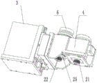
fig. 2 is a schematic structural diagram of the present invention;
FIG. 3 is a schematic view of the structure of the lower part of the mounting seat of the present invention;
fig. 4 is a partial exploded view of the present invention;
fig. 5 is a partial cross-sectional view of the present invention;
in the figure: 1. grinding machine, 2, clamping seat, 3, mounting seat, 4, lifting seat, 5, finishing rotating shaft, 6, diamond finishing head, 7, boss, 8, limiting end cover, 9, lifting screw sleeve, 10, lifting motor, 11, lifting screw, 12, linear guide, 13, lifting block, 14, sliding groove, 15, clamping groove, 16, clamping strip, 17, connecting part, 18, mounting part, 19, avoiding groove, 20, motor, 21, driving belt wheel, 22, driven belt wheel, 23, sleeve, 24, upper protective cover, 25 and lower protective cover.
Detailed Description
The technical solution of the present invention is further described in detail by the following specific embodiments in combination with the accompanying drawings:
example (b): the utility model provides a three bistrique grinding machine dresser structures (refer to fig. 1 to 5), is including removing clamping seat 2, the mount pad 3 of installing on clamping seat on the grinding machine 1 of installing, and the clamping seat is rectangular shape, and the mount pad fastening is installed in the one end of clamping seat, realizes removing through the lead screw structure between grinding machine and the clamping seat, and the motor of installing on the grinding machine drives the lead screw operation, and the lead screw is connected with the clamping seat, converts the rotary motion of lead screw into the removal of clamping seat. The installation goes up and down the lift seat 4 that sets up on the mount pad, and the installation drives moving pivot 5 of repairing by the motor on the lift seat, and the installation diamond is repaiied head 6 in the pivot of repairing. The upper portion of the lifting seat is provided with a boss 7, the diamond trimming head is of an annular structure and is sleeved on the trimming rotating shaft, the upper end of the trimming rotating shaft is connected with a limiting end cover 8, and the diamond trimming head is limited between the limiting end cover and the boss.
The lifting screw sleeve 9 is installed on the lifting seat, the lifting motor 10 is installed on the installation seat, the output shaft of the lifting motor is in transmission connection with the lifting screw rod 11, and the lifting screw rod is in adaptive connection with the lifting screw sleeve. The linear guide 12 of two vertical settings of installation on the mount pad, elevator motor sets up between two linear guide, and the last and linear guide of lift seat correspond installs elevator 13, is equipped with spout 14 on the elevator, and the elevator passes through spout adaptation and connects on linear guide. The side wall of the linear guide rail is provided with a V-shaped clamping groove 15, the side wall of the sliding groove is provided with a clamping strip 16 matched with the clamping groove, and the clamping strip is clamped in the clamping groove. The lifting seat comprises a connecting part 17 and an installation part 18 which are connected together in a fastening mode, the connecting part is arranged between the installation seat and the installation part, the lifting block is installed on the connecting part in a fastening mode, and the trimming rotating shaft is installed on the installation part. An avoiding groove 19 is formed in the mounting seat and opposite to the lifting seat, the lifting motor is mounted on the upper portion of the avoiding groove, and the lifting screw sleeve is arranged in the avoiding groove.
The lifting seat is provided with a motor 20 for driving the finishing rotating shaft to operate, a driving belt wheel 21 is arranged on an output shaft of the motor, a driven belt wheel 22 is arranged on the finishing rotating shaft, and belt transmission is carried out between the driving belt wheel and the driven belt wheel. Install sleeve 23 on the lift seat, the pivot of repairing is installed in the sleeve, and the bearing is all installed to upper portion position and lower part position in the sleeve, and the bearing suit is on repairing the pivot. Protective cover 24 is installed to the sleeve upper end, and protective cover 25 is down installed to the sleeve lower extreme, and the upper and lower both ends of repairing the pivot extend upper protective cover and lower protective cover respectively.
In this application the clamping holder is installed and can be removed on the mill, and the mount pad is fixed and is removed together with the clamping holder on the clamping holder, and the seat that goes up and down is installed and can go up and down to remove on the mount pad, and the maintenance pivot is installed and is gone up and down to remove along with the seat that goes up and down on going up and down to remove on the seat that goes up and down, and diamond is repaiied the head and is installed on maintaining the pivot, consequently, diamond is repaiied the head and goes up and down to remove along with the seat that goes up and down together. When the grinding head on the grinding machine is used for finishing, the clamping seat moves to enable the whole dresser to move to be close to the grinding head, then the grinding head is enabled to be in contact with the diamond finishing head through the movement of the grinding head and the lifting movement of the lifting seat, the finishing rotating shaft runs, and the diamond finishing head is enabled to grind and finish the grinding head.
The above-described embodiments are intended to be illustrative, and not restrictive, and other modifications and variations may be made without departing from the spirit and scope of the invention as defined in the appended claims.
Claims (9)
1. A grinding machine dresser structure with three grinding heads is characterized by comprising a clamping seat movably installed on a grinding machine and a mounting seat fixedly installed on the clamping seat, wherein a lifting seat arranged in a lifting mode is installed on the mounting seat, a dressing rotating shaft driven by a motor to rotate is installed on the lifting seat, and a diamond dresser head is installed on the dressing rotating shaft.
2. The dresser structure of the three-grinding-head grinding machine according to claim 1, wherein the lifting seat is provided with a lifting screw sleeve, the mounting seat is provided with a lifting motor, an output shaft of the lifting motor is in transmission connection with a lifting screw rod, and the lifting screw rod is in adaptive connection with the lifting screw sleeve.
3. The dresser structure of the three-grinding-head grinding machine according to claim 1, wherein two vertically arranged linear guide rails are installed on the installation seat, lifting blocks are installed on the lifting seat and correspond to the linear guide rails, sliding grooves are formed in the lifting blocks, and the lifting blocks are connected to the linear guide rails in a matched mode through the sliding grooves.
4. The dresser structure of a three-grinding-head grinding machine according to claim 3, wherein the side wall of the linear guide rail is provided with a V-shaped clamping groove, the side wall of the sliding chute is provided with a clamping strip matched with the clamping groove, and the clamping strip is clamped in the clamping groove.
5. A dresser structure for a three-wheelhead grinding machine according to claim 3, wherein the lifting block includes a connecting portion and a mounting portion which are fixedly connected together, the connecting portion being interposed between the mounting block and the mounting portion, the lifting block being fixedly mounted on the connecting portion, and the dressing shaft being mounted on the mounting portion.
6. The dresser structure of the three-grinding-head grinding machine according to claim 1, wherein the lifting seat is provided with a motor for driving the dressing rotating shaft to operate, a driving pulley is arranged on an output shaft of the motor, a driven pulley is arranged on the dressing rotating shaft, and a belt is arranged between the driving pulley and the driven pulley.
7. The dresser structure of a three-grinding-head grinding machine according to any one of claims 1 to 6, wherein a boss is arranged at the upper part of a dressing rotating shaft mounted on the lifting seat, the diamond dressing head is sleeved on the dressing rotating shaft, the upper end of the dressing rotating shaft is connected with a limiting end cover, and the diamond dressing head is limited between the limiting end cover and the boss.
8. The dresser structure of a three-grinding-head grinding machine according to any one of claims 1 to 6, wherein a sleeve is mounted on the lifting seat, the dressing rotating shaft is mounted in the sleeve, bearings are mounted at upper and lower positions in the sleeve, and the bearings are sleeved on the dressing rotating shaft.
9. The dresser structure of a three-grinding-head grinding machine according to claim 8, wherein an upper protecting cover is installed at the upper end of the sleeve, a lower protecting cover is installed at the lower end of the sleeve, and the upper protecting cover and the lower protecting cover are respectively extended from the upper end and the lower end of the dressing rotating shaft.
Priority Applications (1)
| Application Number | Priority Date | Filing Date | Title |
|---|---|---|---|
| CN202223403741.3U CN218875086U (en) | 2022-12-19 | 2022-12-19 | Grinding machine dresser structure with three grinding heads |
Applications Claiming Priority (1)
| Application Number | Priority Date | Filing Date | Title |
|---|---|---|---|
| CN202223403741.3U CN218875086U (en) | 2022-12-19 | 2022-12-19 | Grinding machine dresser structure with three grinding heads |
Publications (1)
| Publication Number | Publication Date |
|---|---|
| CN218875086U true CN218875086U (en) | 2023-04-18 |
Family
ID=85955437
Family Applications (1)
| Application Number | Title | Priority Date | Filing Date |
|---|---|---|---|
| CN202223403741.3U Active CN218875086U (en) | 2022-12-19 | 2022-12-19 | Grinding machine dresser structure with three grinding heads |
Country Status (1)
| Country | Link |
|---|---|
| CN (1) | CN218875086U (en) |
-
2022
- 2022-12-19 CN CN202223403741.3U patent/CN218875086U/en active Active
Similar Documents
| Publication | Publication Date | Title |
|---|---|---|
| CN105382659A (en) | Automatic grinding machine | |
| CN205166610U (en) | Automatic grinding machine | |
| CN111015445A (en) | Box-type structure elevator traction sheave processing equipment and processing method thereof | |
| CN218875086U (en) | Grinding machine dresser structure with three grinding heads | |
| CN209986722U (en) | Cambered surface polishing machine | |
| CN110842714A (en) | Multifunctional grinding machine | |
| CN108942441B (en) | Double-sided pot grinding device | |
| CN202462150U (en) | Crystal glass flour milling machine | |
| CN213106280U (en) | Precision grinding equipment for grinding ring | |
| CN212020448U (en) | Grinding wheel repairing device of centerless grinding machine | |
| CN214025054U (en) | Multi-station abrasive belt machine | |
| CN211728700U (en) | Multifunctional grinding machine | |
| CN109909856B (en) | Flexible polishing equipment | |
| CN209811899U (en) | Special efficient cylindrical grinding machine | |
| CN112548798A (en) | Mirror surface polishing machine | |
| CN217266666U (en) | Steel rail polishing mechanism | |
| CN201261152Y (en) | Main spindle elevating gear of crystal glass surface grinder | |
| CN215659571U (en) | Polisher for ring opening | |
| CN108942681A (en) | A kind of grinding machine diamond abrasive wheel dressing device | |
| CN208697012U (en) | A kind of processing of paper machine scraper, polishing all-in-one machine | |
| CN210524750U (en) | Mirror surface polishing machine | |
| CN217530283U (en) | Profile steel end surface cleaning equipment | |
| CN216731174U (en) | Novel automatic sand mill | |
| CN205290713U (en) | Stone material lines buffing wheel feeler mechanism and profiling mechanism that has this feeler mechanism thereof | |
| CN220007160U (en) | Auto-parts polisher of conveniently adjusting |
Legal Events
| Date | Code | Title | Description |
|---|---|---|---|
| GR01 | Patent grant | ||
| GR01 | Patent grant |