CN210432316U - Internal circulation combination heat dissipation formula SVG device - Google Patents
Internal circulation combination heat dissipation formula SVG device Download PDFInfo
- Publication number
- CN210432316U CN210432316U CN201921465942.1U CN201921465942U CN210432316U CN 210432316 U CN210432316 U CN 210432316U CN 201921465942 U CN201921465942 U CN 201921465942U CN 210432316 U CN210432316 U CN 210432316U
- Authority
- CN
- China
- Prior art keywords
- air
- svg
- chamber
- fan
- radiator
- Prior art date
- Legal status (The legal status is an assumption and is not a legal conclusion. Google has not performed a legal analysis and makes no representation as to the accuracy of the status listed.)
- Active
Links
Images


Landscapes
- Cooling Or The Like Of Electrical Apparatus (AREA)
Abstract
The utility model relates to an inner loop combination heat dissipation formula SVG device, include the box and install SVG module in the box, the rear side of SVG module is provided with rather than the sealed chamber of heat dissipation intercommunication, the rear side in sealed chamber is provided with the fan, the heat exchanger is installed to the top of SVG module, and the below is provided with the bottom chamber, the air conditioner chamber of SVG front side for installing the air conditioner, the radiator of SVG module, sealed chamber, fan, heat exchanger and air conditioner chamber, perhaps the radiator of SVG module, sealed chamber, fan, bottom chamber and air conditioner chamber form two circulation heat dissipation passageways, wherein the air in the radiator can pass through in proper order get into in the radiator again behind sealed chamber, fan, heat exchanger or bottom chamber and the air conditioner. The utility model discloses an air-cooled form of inner loop dispels the heat to the SVG module, avoids the external environment to the influence of SVG device to guarantee SVG device normal operating.
Description
Technical Field
The utility model belongs to the technical field of the SVG device heat dissipation, concretely relates to inner loop combination heat dissipation formula SVG device.
Background
Conventional SVG capacity is basically at 1~50M interval, the capacity is great more the loss that corresponds, calorific capacity needs to adopt forced air cooling or water-cooling to realize the heat dissipation, adopt the forced air cooling all to dispel the heat through the extrinsic cycle among the traditional mode, carry out a large amount of air currents or amount of wind exchange with the external world, and when the SVG device is in environment such as high sand blown by wind high humidity or high salt fog, impurity or steam in the external air current etc. can cause very big influence to the operation of SVG module, can cause the condition of its fault damage even.
SUMMERY OF THE UTILITY MODEL
The utility model aims at providing an inner loop combination heat dissipation formula SVG device to external environment produces the problem of influence to the SVG module when solving the forced air cooling heat dissipation.
The utility model discloses an inner loop combination heat dissipation formula SVG device is realized like this:
an internal circulation combined heat dissipation type SVG device,
including the box and installing SVG module in the box, include the box and install SVG module in the box, the rear side of SVG module is provided with the sealed chamber rather than the radiator intercommunication, the rear side in sealed chamber is provided with the fan, the heat exchanger is installed to the top of SVG module, and the below is provided with the bottom chamber, SVG module front side is the air-conditioning chamber of installing the air conditioner, the radiator of SVG module, sealed chamber, fan, heat exchanger and air-conditioning chamber, perhaps the radiator of SVG module, sealed chamber, fan, bottom chamber and air-conditioning chamber form two circulation heat dissipation passageways respectively, wherein the air in the radiator can pass through in proper order sealed chamber, fan, heat exchanger or bottom chamber and air-conditioning chamber back reentrant radiator.
Furthermore, the preceding air outlet of the radiator of SVG module with air conditioner chamber intercommunication, the back air outlet of the radiator of SVG module with sealed chamber intercommunication.
Furthermore, an air inlet and an air outlet of the air conditioner are respectively communicated with the air conditioner cavity, and the air conditioner is installed on a box door on the front side of the box body.
Furthermore, an air duct is arranged on the rear side of the sealed cavity, the fan is installed in the air duct, an air inlet of the fan is communicated with the sealed cavity, and an air outlet of the fan is communicated with the air duct.
Furthermore, a fan mounting opening is formed in the rear wall of the box body, and a sealing door is hinged to the fan mounting opening.
Further, the top of SVG module be provided with the last wind channel of wind channel and air conditioner chamber intercommunication, just the air intake and the air outlet of heat exchanger respectively with last wind channel intercommunication.
Furthermore, the bottom cavity is respectively communicated with the air conditioning cavity and the air duct, and a ventilation window is arranged between the bottom cavity and the air conditioning cavity.
Furthermore, the SVG module includes a plurality ofly, and installs on the mount according to upper and lower and left and right parallel mode.
After the technical scheme is adopted, the utility model discloses the beneficial effect who has does:
(1) the utility model adopts the internal circulation air cooling mode to radiate the SVG module, thereby avoiding the influence of the external environment on the SVG device and ensuring the normal operation thereof;
(2) the utility model discloses combine fan, heat exchanger and fan, can adjust the heat dissipation that realizes the SVG module through the mode of multiple combination according to different environment, improved radiating effect and radiating efficiency.
Drawings
The present invention will be further explained with reference to the drawings and examples.
Fig. 1 is a structural diagram of an internal circulation combined heat dissipation type SVG apparatus according to a preferred embodiment of the present invention;
fig. 2 is a structural diagram of an internal circulation combined heat dissipation type SVG apparatus according to a preferred embodiment of the present invention;
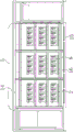
fig. 3 is a front view of an internal circulation combined heat dissipation type SVG apparatus according to a preferred embodiment of the present invention;
FIG. 4 is a cross-sectional view taken along line A-A of FIG. 3;
FIG. 5 is a cross-sectional view taken along line C-C of FIG. 3;
fig. 6 is a right side view of the internal circulation combined heat dissipation SVG apparatus according to the preferred embodiment of the present invention;
FIG. 7 is a cross-sectional view taken along line D-D of FIG. 6;
FIG. 8 is a cross-sectional view taken along line E-E of FIG. 6;
in the figure: the box 1, SVG module 2, sealed chamber 3, fan 4, heat exchanger 5, end chamber 6, air conditioner chamber 7, preceding air inlet 8, back air outlet 9, air conditioner 10, wind channel 11, fan installing port 12, sealing door 13, last wind channel 14, ventilation window 15, mount 16, chamber door 17.
Detailed Description
To make the objects, technical solutions and advantages of the embodiments of the present invention clearer, the drawings of the embodiments of the present invention are combined to clearly and completely describe the technical solutions of the embodiments of the present invention, and obviously, the described embodiments are some embodiments of the present invention, not all embodiments.
Thus, the following detailed description of the embodiments of the present invention, presented in the accompanying drawings, is not intended to limit the scope of the invention, as claimed, but is merely representative of selected embodiments of the invention. Based on the embodiments in the present invention, all other embodiments obtained by a person skilled in the art without creative work belong to the protection scope of the present invention.
As shown in fig. 1-8, an inner loop combination heat dissipation formula SVG device, include box 1 and install SVG module 2 in the box 1, SVG module 2's rear side is provided with sealed chamber 3 rather than the radiator intercommunication, sealed chamber 3's rear side is provided with fan 4, heat exchanger 5 is installed to SVG module 2's top, and the below is provided with bottom chamber 6, the air conditioner chamber 7 of SVG module 2 front side for installing air conditioner 10, SVG module 2's radiator, sealed chamber 3, fan 4, heat exchanger 5 and air conditioner chamber 6, perhaps SVG module 2's radiator, sealed chamber 3, fan 4, bottom chamber 6 and air conditioner chamber 7 form two circulation heat dissipation passageways respectively, and wherein the air in the radiator can pass through in proper order sealed chamber 3, fan 4, heat exchanger 5 or bottom chamber 6 and air conditioner chamber 7 back get into in the radiator again.
Specifically, the radiators of the SVG modules 2 are connected with the same sealed cavity 3, and the air inlet of the fan 4 is directly installed on the rear wall of the sealed cavity 3 and communicated with the sealed cavity.
Use sealed chamber 3 to communicate fan 4 and SVG module 2's radiator, and do not directly utilize fan 4 to communicate the radiator, can satisfy SVG module 2's electrical clearance requirement to can realize the even radiating effect to a plurality of SVG modules 2 through sealed chamber 3.
In order to realize the inside circulation of air of the radiator of SVG module 2, the preceding air outlet 8 of the radiator of SVG module 2 with air-conditioning chamber 7 intercommunication, the back air outlet 9 of the radiator of SVG module 2 with sealed chamber 3 intercommunication.
The air conditioner 10 is only used for air circulation in the box body 1 and does not exchange with outside air, wherein in order to ensure that the air conditioner 10 can participate in the internal circulation, an air inlet and an air outlet of the air conditioner 10 are respectively communicated with the air conditioning cavity 7, and the air conditioner 10 is installed on a box door 17 on the front side of the box body 1.
The cold air through air conditioner 10 or the heat exchanger 5 cooling is through going into in the radiator of SVG module 2 of air inlet 8 entering, carry out the heat exchange with the radiator to cool down SVG module 2, then the hot-air after the heat exchange then gets into in the sealed chamber 3 through back air outlet 9.
In order to realize the circulation of air flow, an air duct 11 is arranged at the rear side of the sealed cavity 3, the fan 4 is installed in the air duct 11, an air inlet of the fan 4 is communicated with the sealed cavity 3, and an air outlet of the fan 4 is communicated with the air duct 11.
The effect of fan 4 is for the air cycle in the box 1 provides power, and it can take the hot-air in the sealed chamber 3 out and send into wind channel 11, then cools down through heat exchanger 5 or air conditioner once more, is convenient for carry out the cooling work of next circulation to SVG module 2.
In order to facilitate the installation of the fan 4, a fan installation opening 12 is formed in the rear wall of the box body 1, and a sealing door 13 is hinged to the fan installation opening 12.
In order to realize the cooling of the internal circulating air by the heat exchanger 5, an upper air duct 14 communicated with the air duct 11 and the air conditioning cavity 7 is arranged above the SVG module 2, and the air inlet and the air outlet of the heat exchanger 5 are respectively communicated with the upper air duct 14.
The hot air discharged into the air duct 11 by the fan 4 can contact with the heat exchanger 5 through the upper air duct 14, then is cooled, enters the air conditioning cavity 7 again, and enters the front air inlet 8 after being cooled by the air conditioner again to cool the SVG module 2.
Preferably, the heat exchanger 5 can be a plate heat exchanger, and has a large contact area and a good heat exchange effect.
In order to realize the air circulation below the SVG module 2, the bottom cavity 6 is respectively communicated with the air conditioning cavity 7 and the air duct 11, and is provided with a ventilation window 15 between the air conditioning cavity 7.
The bottom cavity 6 is communicated with the air duct 11 and the air conditioning cavity 7 by adopting a grid plate, and preferably, the ventilation window 15 is a detachable grid plate.
The hot air entering the air duct 11 by the fan 4 can be directly sent into the air conditioning cavity 7 through the bottom cavity 6, and then sent into the radiator again through the cooling of the air conditioner 10 to realize the cooling effect.
The SVG module 2 includes a plurality of SVG modules, and is mounted on the fixing frame 16 in an up-down and left-right parallel manner.
A plurality of SVG modules 2 evenly distributed can guarantee its radiating effect.
The hot air and the cold air proposed in the present embodiment refer to relative temperatures of air in two states.
Referring to FIG. 4, the direction of the arrows indicates the direction of the internal circulation air flow. Specifically, when carrying out the inner loop cooling, the cold air through heat exchanger 5 and air conditioner 10 gets into in the radiator of SVG module 2 through advancing wind gap 8, carry out the heat exchange, cool down the radiator, the hot-air through the heat exchange then gets into sealed chamber 3 and utilizes fan 4 to take out through the back air outlet 9 of radiator, get into in wind channel 11, the hot-air that gets into wind channel 11 then cools down through the heat exchanger 5 of last wind channel 14, and get into SVG module 2 front side and utilize air conditioner 10 to cool down through end cavity 6, form cold air once more and get into the radiator and carry out the heat exchange.
When the inner loop cooling, the box 1 that this embodiment provided is totally enclosed structure, and the protection level is IP65, can be effective mode external environment to the influence of inside SVG module. In this embodiment, the SVG module 2, the fan 4 for heat dissipation, the heat exchanger 5 and the air conditioner 10 are all concentrated in one box body 1, so that the complexity of field installation can be reduced, the heat exchanger is suitable for various severe environments, and the practicability is high.
In light of the foregoing, it will be apparent to those skilled in the art from this disclosure that various changes and modifications can be made without departing from the spirit and scope of the invention. The technical scope of the present invention is not limited to the content of the specification, and must be determined according to the scope of the claims.
Claims (8)
1. The utility model provides an inner loop combination heat dissipation formula SVG device, a serial communication port, include box (1) and install SVG module (2) in box (1), the rear side of SVG module (2) is provided with sealed chamber (3) rather than radiator intercommunication, the rear side of sealed chamber (3) is provided with fan (4), heat exchanger (5) are installed to the top of SVG module (2), and the below is provided with bottom chamber (6), air conditioner chamber (7) of SVG module (2) front side for installing air conditioner (10), the radiator of SVG module (2), sealed chamber (3), fan (4), heat exchanger (5) and air conditioner chamber (7), perhaps the radiator of SVG module (2), sealed chamber (3), fan (4), bottom chamber (6) and air conditioner chamber (7) form two circulation heat dissipation passageways respectively, wherein the air in the radiator can pass through in proper order sealed chamber (3), The fan (4), the heat exchanger (5) or the bottom cavity (6) and the air conditioning cavity (7) enter the radiator again.
2. The internal-circulation combined-heat-dissipation SVG device according to claim 1, characterized in that the front air outlet (8) of the radiator of said SVG module (2) communicates with said air-conditioning chamber (7), and the rear air outlet (9) of the radiator of said SVG module (2) communicates with said sealed chamber (3).
3. An SVG device with internal circulation combined heat dissipation according to claim 2, wherein the air inlet and the air outlet of the air conditioner (10) are communicated with the air conditioning chamber (7), respectively, and the air conditioner (10) is mounted on a door (17) of the front side of the cabinet (1).
4. The internal circulation combined heat dissipation SVG device according to claim 1, characterized in that, the rear side of said sealed chamber (3) is provided with an air duct (11), said fan (4) is installed in said air duct (11), the air inlet of said fan (4) is communicated with said sealed chamber (3), and the air outlet is communicated with said air duct (11).
5. The SVG device of claim 1, wherein said box (1) is provided with a fan mounting port (12) on its rear wall, and said fan mounting port (12) is hinged with a sealing door (13).
6. The internal circulation combined heat dissipation SVG device according to claim 4, characterized in that an upper air duct (14) communicating with said air duct (11) and air conditioning chamber (7) is provided above said SVG module (2), and the air intake and air outlet of said heat exchanger (5) are respectively communicated with said upper air duct (14).
7. An SVG device with combined heat dissipation by internal circulation according to claim 4, characterized in that said bottom chamber (6) communicates with air-conditioning chamber (7) and air duct (11), respectively, and a ventilation window (15) is provided between it and said air-conditioning chamber (7).
8. The inner-circulation combined-heat-dissipating SVG device according to claim 1, wherein said SVG module (2) comprises a plurality and is mounted on a mount (16) in a side-by-side manner up and down and left and right.
Priority Applications (1)
| Application Number | Priority Date | Filing Date | Title |
|---|---|---|---|
| CN201921465942.1U CN210432316U (en) | 2019-09-04 | 2019-09-04 | Internal circulation combination heat dissipation formula SVG device |
Applications Claiming Priority (1)
| Application Number | Priority Date | Filing Date | Title |
|---|---|---|---|
| CN201921465942.1U CN210432316U (en) | 2019-09-04 | 2019-09-04 | Internal circulation combination heat dissipation formula SVG device |
Publications (1)
| Publication Number | Publication Date |
|---|---|
| CN210432316U true CN210432316U (en) | 2020-04-28 |
Family
ID=70366065
Family Applications (1)
| Application Number | Title | Priority Date | Filing Date |
|---|---|---|---|
| CN201921465942.1U Active CN210432316U (en) | 2019-09-04 | 2019-09-04 | Internal circulation combination heat dissipation formula SVG device |
Country Status (1)
| Country | Link |
|---|---|
| CN (1) | CN210432316U (en) |
-
2019
- 2019-09-04 CN CN201921465942.1U patent/CN210432316U/en active Active
Similar Documents
| Publication | Publication Date | Title |
|---|---|---|
| CN108495538B (en) | High-power outdoor heat dissipation rack | |
| CN202587697U (en) | Automatically controlled box and air conditioner's off-premises station | |
| CN206977887U (en) | A kind of rack semiconductor cooling device | |
| CN105042719A (en) | Outdoor machine of air conditioner | |
| CN213126970U (en) | Air-cooled heat dissipation system of VPX framework case | |
| CN110785064B (en) | Electric control assembly and hot water air conditioner | |
| CN210432316U (en) | Internal circulation combination heat dissipation formula SVG device | |
| CN201995273U (en) | Heat dissipating device for electronic control system of air conditioner outdoor unit | |
| CN209962840U (en) | Novel cooling structure of dry-type transformer | |
| CN116053604A (en) | Formation cabinet with heat dissipation function | |
| CN211378618U (en) | Fin structure for air-cooled radiator | |
| CN204902043U (en) | Outdoor machine of air conditioner | |
| CN114679129A (en) | Photovoltaic power generation assembly based on closed air cavity cooling and cooling method | |
| CN212109064U (en) | Semiconductor refrigerating system and smoke exhaust ventilator using same | |
| CN219659668U (en) | Photovoltaic module junction box | |
| CN107124855B (en) | Outdoor closed air-cooled cabinet | |
| CN216752519U (en) | Air guide assembly for 5G BBU cabinet | |
| CN214413332U (en) | Heat radiation structure of heating equipment host | |
| CN210959286U (en) | Air conditioning device for outdoor cabinet | |
| CN217884274U (en) | Dustproof PLC switch board of heat dissipation based on forced air cooling | |
| CN220139588U (en) | Switch with dampproofing function | |
| CN221653036U (en) | Cabinet type energy storage system | |
| CN214851650U (en) | Closed switch shell and switch | |
| CN221614481U (en) | Outdoor power distribution cabinet | |
| CN221467192U (en) | Circulation wind channel and dust removal power cabinet |
Legal Events
| Date | Code | Title | Description |
|---|---|---|---|
| GR01 | Patent grant | ||
| GR01 | Patent grant |