CN210203145U - Phosphorus-free fish viscera descaling machine - Google Patents
Phosphorus-free fish viscera descaling machine Download PDFInfo
- Publication number
- CN210203145U CN210203145U CN201921007784.5U CN201921007784U CN210203145U CN 210203145 U CN210203145 U CN 210203145U CN 201921007784 U CN201921007784 U CN 201921007784U CN 210203145 U CN210203145 U CN 210203145U
- Authority
- CN
- China
- Prior art keywords
- fish
- sliding
- bearing
- rotating rod
- phosphorus
- Prior art date
- Legal status (The legal status is an assumption and is not a legal conclusion. Google has not performed a legal analysis and makes no representation as to the accuracy of the status listed.)
- Active
Links
Images


Abstract
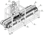
The utility model relates to a phosphorus-free fish viscera descaling machine belongs to fish processing equipment technical field. This phosphorus-free fish viscera descaling machine contains the frame, bears mould, transfer chain, brush ware and locator: a transmission chain is arranged on the frame through a transmission chain wheel and a transmission motor which are symmetrically arranged; a plurality of bearing clamping fixtures are uniformly arranged on the conveying chain; a brush remover is arranged on the machine frame above the conveying chain; the rack on one side of the conveying chain is movably provided with an assembling rotating rod; a driving cylinder is hinged on the rack above one side of the assembling rotating rod; the driving cylinder is connected with the assembling rotating rod through a hinged driving swing arm; a plurality of positioners are uniformly arranged on the assembling rotating rod. The phosphorus-free fish viscera cleaning machine is compact in structure and ingenious in design, can be used for mechanically removing viscera of eel and loach, solves the problems of high labor intensity and low working efficiency when viscera are removed manually, and meets the requirements of enterprises for production and use.
Description
Technical Field
The utility model relates to a phosphorus-free fish viscera descaling machine belongs to fish processing equipment technical field.
Background
The phosphorus-free fish such as eel and loach is one of the daily delicacies of the dining table, and is deeply favored by people due to the characteristics of rich nutritive value and delicious taste. In order to meet the taste of people, various food processing enterprises take eel and loach as basic raw materials, carry out industrial deep processing on the basic raw materials, and research and develop various types of instant food. In the industrial processing process of the eels and the loaches, the eels and the loaches need to be subjected to a plurality of steps of killing, removing internal organs, cleaning and the like. The eel and the loach have the characteristics of sticky and smooth surface and fine diameter; after the belly is cut by equipment, the internal organs still need to be manually removed, so that the problems of high labor intensity and low working efficiency exist; the requirements of enterprises for production and use cannot be met; therefore, there is a need to develop a viscera removing device, which can mechanically remove viscera of eel, so as to solve the above problems existing in artificial viscera removal.
Disclosure of Invention
The utility model aims to provide a: the phosphorus-free fish viscera cleaning machine has a compact structure and ingenious design and solves the problems of high labor intensity and low working efficiency when the viscera of the eels are manually removed.
The technical scheme of the utility model is that:
a phosphorus-free fish viscera cleaning machine comprises a frame, a bearing mould, a conveying chain, a brushing device and a positioner; the method is characterized in that: a transmission chain is arranged on the frame through a transmission chain wheel and a transmission motor which are symmetrically arranged; a plurality of bearing clamping fixtures are uniformly arranged on the conveying chain; a brush remover is arranged on the machine frame above the conveying chain; the rack on one side of the conveying chain is movably provided with an assembling rotating rod; a driving cylinder is hinged on the rack above one side of the assembling rotating rod; the driving cylinder is connected with the assembling rotating rod through a hinged driving swing arm; when the driving cylinder works, the driving swing arm can drive the assembling rotating rod to rotate back and forth; a plurality of positioners are uniformly arranged on the assembling rotating rod; the positioner is arranged opposite to one end of the bearing mould.
The bearing mould consists of an assembly bottom plate, a fish bearing seat and a blocking piece; the conveying chain is fixedly connected with an assembly bottom plate; a fish bearing seat is fixedly arranged on the assembly bottom plate; the upper end of the fish bearing seat is provided with a fish bearing groove with one end inclined downwards; the end of the fish bearing groove is fixedly provided with a baffle plate through a screw.
The section of the fish bearing groove is of a V-shaped structure.
The brushing device consists of a lifting frame, a sliding seat, a lifting motor, a sliding motor and a dirt removing brush roll; a lifting frame is arranged on the rack in a sliding way through a sliding rail; one side of the lifting frame is provided with a driving screw rod through a lifting motor; the driving screw rod is in threaded connection with the lifting frame; the lower end face of the lifting frame is provided with a sliding seat in a sliding way through a guide sliding rail; the lifting frame is provided with a sliding screw rod through a sliding motor; the sliding screw rod is in threaded connection with the sliding seat; the lower end of the sliding seat is provided with a dirt removing brush roll through a bearing seat; one end of the dirt removing brush roll is connected with a dirt removing motor arranged on the sliding seat through a transmission belt.
The guide sliding rail is arranged in an inclined shape.
The dirt removing brush roll is provided with a plurality of circles of dirt removing bristles; the dirt removing brush hair and the bearing mould are arranged oppositely.
The positioner consists of a rotating plate, an isolating elastic sheet, a fixed contact pin and a return spring; one end of the rotating plate is provided with an assembling hole in the key groove; the rotating plate is fixedly arranged on the assembling rotating rod through the assembling hole; the other end of the rotating plate is fixedly provided with a fixed contact pin; the bottom end of the rotating plate is fixedly provided with an isolating elastic sheet through a screw; one end of the isolating elastic sheet is provided with an avoidance port; the avoidance port is connected with the fixed contact pin in a plugging way; the middle part of the rotating plate is fixedly provided with an assembly sleeve; the guide rod with the T-shaped lower end penetrates through the isolating elastic sheet and then is in threaded connection with the assembling sleeve; the isolating elastic sheet is intermittently abutted and connected with the T-shaped part of the guide rod; a return spring is sleeved on the guide rod above the isolating elastic sheet; the reset spring is connected with the isolation elastic sheet and the assembly sleeve in an abutting mode.
The utility model has the advantages that:
the phosphorus-free fish viscera cleaning machine is compact in structure and ingenious in design, and can be used for mechanically removing viscera of eel and loach, so that the problems of high labor intensity and low working efficiency existing in manual viscera removal are solved, and the requirements of enterprises on production and use are met.
Drawings
Fig. 1 is a schematic structural view of the present invention;
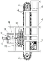
fig. 2 is a schematic view of the structure of the present invention;
fig. 3 is a left side view structure diagram of the present invention;
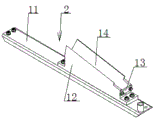
FIG. 4 is a schematic structural view of the load-bearing mold of the present invention;
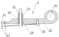
FIG. 5 is an enlarged schematic view of the structure at A in FIG. 1;
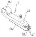
FIG. 6 is a schematic view of the positioner;
FIG. 7 is a schematic cross-sectional view of FIG. 6;
fig. 8 is a schematic structural view of the brush roller for removing dirt according to the present invention.
In the figure: 1. the device comprises a rack, 2, a bearing mould, 3, a conveying chain, 4, a brushing device, 5, a positioner, 6, a transmission chain wheel, 7, a transmission motor, 8, an assembly rotating rod, 9, a driving cylinder, 10, a driving swing arm, 11, an assembly bottom plate, 12, a fish bearing seat, 13, a baffle plate, 14, a fish bearing groove, 15, a lifting frame, 16, a sliding seat, 17, a lifting motor, 18, a sliding motor, 19, a dirt removing brush roll, 20, a driving screw rod, 21, a guide sliding rail, 22, a sliding screw rod, 23, a dirt removing motor, 24, dirt removing bristles, 25, a rotating plate, 26, an isolating elastic sheet, 27, a fixed contact pin, 28, a reset spring, 29, an assembly hole, 30, a screw, 31, an avoiding hole, 32, an assembly cover, 33 and a guide rod.
Detailed Description
The phosphorus-free fish viscera cleaning machine comprises a frame 1, a bearing clamping fixture 2, a conveying chain 3, a brushing device 4 and a positioner 5 (see the attached figures 1, 2 and 3 in the specification).
A transmission chain 3 (refer to the attached figure 3 in the specification) is symmetrically arranged on the frame 1 through a transmission chain wheel 6 and a transmission motor 7 which are symmetrically arranged; a plurality of bearing clamping molds 2 are uniformly arranged on the conveying chain 3 (see the attached figure 2 in the specification); when the transmission motor 7 works, the transmission chain wheel 6 can drive the transmission chain 3 to rotate ceaselessly; the conveying chain 3 drives the bearing mould 2 to synchronously rotate in the rotating process.
The bearing clamping fixture 2 is composed of an assembly bottom plate 11, a fish bearing seat 12 and a baffle plate 13 (see the attached figure 4 in the specification); the transmission chain 3 is fixedly connected with an assembly bottom plate 11; a fish bearing seat 12 is fixedly arranged on the assembly bottom plate 11; the upper end of the fish bearing seat 12 is provided with a fish bearing groove 14 with one end inclined downwards; the end of the fish bearing groove 14 is fixedly provided with a baffle plate 13 through a screw (see the description and the attached figure 4). The purpose of such a fish receiving groove 14 is: so that during operation, after eel or loach which is split into sections is placed in the fish bearing groove 14 from one end of the fish bearing seat 12, the eel or loach can slide down along the fish bearing groove 14 to a state that the head of the eel or loach is abutted against the baffle 13 under the action of gravity.
The section of the fish bearing groove 14 is in a V-shaped structure (see the attached figure 4 in the specification). The purpose of such a fish receiving groove 14 is: so that the eels or the loaches with various diameters can smoothly slide down the fish bearing grooves 14 under the guidance of the V-shaped structure fish bearing grooves 14, thereby avoiding that the eels or the loaches cannot slide down the fish bearing grooves 14 in a horizontal state when the fish bearing grooves 14 are in other structures, and ensuring that the eels or the loaches can be placed in the fish bearing grooves 14 in the same posture.
A brush remover 4 is mounted on the frame 1 above the conveyor chain 3 (see figures 1, 2 and 3 of the specification).
The brush remover 4 is composed of a lifting frame 15, a sliding seat 16, a lifting motor 17, a sliding motor 18 and a dirt removing brush roll 19 (see the attached figure 3 in the specification); the frame 1 is provided with a lifting frame 15 through a slide rail in a sliding way; one side of the lifting frame 15 is provided with a driving screw rod 20 through a lifting motor 17; the driving screw rod 20 is in threaded connection with the lifting frame 15; when the lifting motor 17 drives the driving screw rod 20 to work, the lifting frame 15 can be driven to move up and down in the vertical direction.
The lower end surface of the lifting frame 15 is provided with a sliding seat 16 in a sliding way through a guide sliding rail 21; the lifting frame 15 is provided with a sliding screw rod 22 through a sliding motor 18; the sliding screw rod 22 is in threaded connection with the sliding seat 16 (see the attached figure 3 in the specification); when the sliding motor 18 drives the sliding screw rod 22 to work, the sliding base 16 can be driven to move back and forth along the guide slide rail 21.
The guide rail 21 is provided in an inclined manner. The purpose of arranging the guide slide rail 21 in an "inclined" shape is to: so that slide 16 can be along "incline the orbit" motion under the guide of direction slide rail 21 to make slide 16 drive and remove dirty brush roll 19 from the upward motion in-process down, remove the dirty brush hair 24 among the dirty brush roll 19 and can remove eel viscera along same angle and same gesture, so can avoid removing dirty brush hair 24 course of operation, the emergence of the inconsistent problem of effect that leads to of removing dirty brush hair 24 gesture.
The lower end of the sliding seat 16 is provided with a dirt removing brush roll 19 through a bearing seat; one end of the dirt removing brush roll 19 is connected with a dirt removing motor 23 arranged on the sliding seat 16 through a transmission belt (see the attached figure 3 in the specification). When the dirt removing motor 23 works, the dirt removing brush roll 19 can be driven to synchronously rotate through the transmission belt.
The dirt removing brush roll 19 is provided with a plurality of circles of dirt removing bristles 24; the dirt removing brush 24 is arranged opposite to the bearing mould 2 (see the description and the attached figure 8). When the dirt removing brush roll 19 rotates, the dirt removing brush roll 19 can remove the internal organs of the eels through the dirt removing brush hairs 24.
An assembly rotating rod 8 (refer to the attached figures 3 and 5 in the specification) is movably arranged on the frame 1 at one side of the conveying chain 3; a driving cylinder 9 is hinged on the frame 1 above one side of the assembling rotating rod 8; the driving cylinder 9 is connected with the assembling rotating rod 8 through a hinged driving swing arm 10; when the driving cylinder 9 works, the assembly rotating rod 8 can be driven to rotate back and forth by the driving swing arm 10.
A plurality of locators 5 are uniformly arranged on the assembling rotating rod 8; the positioner 5 is arranged opposite to one end of the bearing mould 2.
The positioner 5 is composed of a rotating plate 25, an isolating elastic sheet 26, a fixed contact pin 27 and a return spring 28 (see the description of figures 6 and 7); one end of the rotating plate 25 is provided with an assembling hole 29 in the key groove; the rotating plate 25 is fixedly arranged on the assembling rotating rod 8 through an assembling hole 29 (see the description and the attached drawings 6 and 7); when the rotating rod 8 is assembled in this way, the rotating plate 25 can drive the positioner 5 to rotate synchronously.
The other end of the rotating plate 25 is fixedly provided with a fixed contact pin 27; the bottom end of the rotating plate 25 is fixedly provided with an isolating elastic sheet 26 through a screw 30. The isolating spring 26 is in an open state with the rotating plate 25 under the action of its own elastic force (see fig. 6 and 7 in the specification).
One end of the isolating elastic sheet 26 is provided with an avoidance port 31; the avoiding port 31 is connected with the fixed contact pin 27 in a plugging way; the middle part of the rotating plate 25 is fixedly provided with an assembly sleeve 32; a guide rod 33 with a T-shaped lower end penetrates through the isolating elastic sheet 26 and then is in threaded connection with the assembling sleeve 32; the isolating elastic sheet 26 is intermittently abutted and connected with the T part of the guide rod 33; a return spring 28 is sleeved on the guide rod 33 above the isolation elastic sheet 26; the return spring 28 is in abutting connection with the isolating spring plate 26 and the mounting sleeve 32.
When the phosphorus-free fish viscera cleaning machine works, firstly, eels or loaches which have already completed laparotomy are put into a plurality of fish bearing grooves 14 of the bearing clamping fixture 2 on one side of the brushing device 4 in an upward belly posture. The section of the fish bearing groove 14 is of a V-shaped structure; and the eel or the loach is obliquely arranged, so that after the eel or the loach is placed into the fish bearing groove 14, the eel or the loach slides downwards under the action of self gravity and finally takes the posture that the head of the eel or the loach is abutted against the blocking piece 13 and the split belly is upward.
After the eel or the loach is placed, the transmission motor 7 acts, and drives each bearing mould 2 to move backwards through the transmission chain wheel 6 and the transmission chain 3; when the bearing mould 2 loaded with the eels or the loaches and the locators 5 are in opposite states, the transmission motor 7 stops acting.
Then the driving cylinder 9 drives the assembling rotating rod 8 and each positioner 5 to rotate downwards through the driving swing arm 10; when the fixed pin 27 on the positioner 5 inserts and fastens the head of the eel or the loach in the bearing mould 2, the driving cylinder 9 stops acting.
After the processes are finished, the dirt removing motor 23 drives the dirt removing brush roll 19 to synchronously rotate through the transmission belt. Then the lifting motor 17 drives the lifting frame 15 to move downwards through the driving screw rod 20; when the dirt removing brush 24 on the dirt removing brush roll 19 is contacted with one end of the head of the eel or the loach, the lifting motor 17 stops.
Then, the sliding motor 18 drives the sliding base 16 to move backwards along the guide sliding rail 21 through the sliding screw rod 22. In the process that the sliding seat 16 moves backwards, the internal organs of the eels or the loaches which are already cut open can be removed by the rotating internal organs removing bristles 24; when the dirt removing brush bristles 24 on the dirt removing brush roll 19 move backwards to be separated from the fish bearing seat 12, the lifting motor 17 drives the lifting frame 15 to reset through the driving screw rod 20.
In the process, the eel or the loach which is split into the abdomen is manually placed into the subsequent bearing mould 2 in a posture that the belly is upward.
After the above processes are finished, the driving cylinder 9 drives the assembling rotating rod 8 and each positioner 5 to rotate upwards and reset through the driving swing arm 10. During the process of upward rotation of each retainer 5; the rotating plate 25 in the positioner 5 is first rotated upwards, and the isolating elastic sheet 26 keeps abutting against the fish bearing seat 12 of the bearing mould 2 under the action of the self elasticity and the elasticity of the return spring 28; therefore, when the fixed contact pin 27 at one end of the rotating plate 25 drives the head of the eel or the loach to start, the isolating elastic sheet 26 can pick the eel or the loach from the fixed contact pin 27 to enable the eel or the loach to fall into the fish bearing seat 12 again, and then the rotating plate 25 continues to rotate to drive the isolating elastic sheet 26 to reset, and then the air cylinder 9 is driven to stop acting.
After the processes are finished, the transmission motor 7 acts to drive each bearing mould 2 to move backwards through the transmission chain wheel 6 and the transmission chain 3; when the next batch of bearing clamping tools 2 filled with the eels or the loaches and the locators 5 are in opposite states, the phosphorus-free fish viscera cleaning machine can enter the next working cycle.
The phosphorus-free fish viscera cleaning machine is compact in structure and ingenious in design, and can be used for mechanically removing viscera of eel and loach, so that the problems of high labor intensity and low working efficiency existing in manual viscera removal are solved, and the requirements of enterprises on production and use are met.
Claims (7)
1. A phosphorus-free fish viscera cleaning machine comprises a frame (1), a bearing mould (2), a conveying chain (3), a brush remover (4) and a positioner (5); the method is characterized in that: a transmission chain (3) is arranged on the frame (1) through a transmission chain wheel (6) and a transmission motor (7) which are symmetrically arranged; a plurality of bearing clamping tools (2) are uniformly arranged on the conveying chain (3); a brush remover (4) is arranged on the frame (1) above the conveying chain (3); an assembly rotating rod (8) is movably arranged on the rack (1) at one side of the conveying chain (3); a driving cylinder (9) is hinged on the rack (1) above one side of the assembling rotating rod (8); the driving cylinder (9) is connected with the assembling rotating rod (8) through a hinged driving swing arm (10); when the driving cylinder (9) works, the assembly rotating rod (8) can be driven to rotate back and forth by the driving swing arm (10); a plurality of positioners (5) are uniformly arranged on the assembling rotating rod (8); the positioner (5) is arranged opposite to one end of the bearing mould (2).
2. The fish viscera cleaning machine without phosphorus according to claim 1, characterized in that: the bearing mould (2) consists of an assembly bottom plate (11), a fish bearing seat (12) and a blocking piece (13); the conveying chain (3) is fixedly connected with an assembly bottom plate (11); a fish bearing seat (12) is fixedly arranged on the assembly bottom plate (11); the upper end of the fish bearing seat (12) is provided with a fish bearing groove (14) with one end inclined downwards; the end of the fish bearing groove (14) is fixedly provided with a baffle plate (13) through a screw.
3. The fish viscera cleaning machine without phosphorus according to claim 2, characterized in that: the section of the fish bearing groove (14) is of a V-shaped structure.
4. The fish viscera cleaning machine without phosphorus according to claim 3, characterized in that: the brush remover (4) consists of a lifting frame (15), a sliding seat (16), a lifting motor (17), a sliding motor (18) and a dirt removing brush roll (19); a lifting frame (15) is arranged on the rack (1) in a sliding way through a sliding rail; one side of the lifting frame (15) is provided with a driving screw rod (20) through a lifting motor (17); the driving screw rod (20) is in threaded connection with the lifting frame (15); the lower end surface of the lifting frame (15) is provided with a sliding seat (16) in a sliding way through a guide sliding rail (21); a sliding screw rod (22) is arranged on the lifting frame (15) through a sliding motor (18); the sliding screw rod (22) is in threaded connection with the sliding seat (16); the lower end of the sliding seat (16) is provided with a dirt removing brush roll (19) through a bearing seat; one end of the dirt removing brush roll (19) is connected with a dirt removing motor (23) arranged on the sliding seat (16) through a transmission belt.
5. The fish viscera cleaning machine without phosphorus according to claim 4, characterized in that: the guide slide rail (21) is arranged in an inclined shape.
6. The fish viscera cleaning machine without phosphorus according to claim 5, characterized in that: a plurality of circles of dirt removing bristles (24) are arranged on the dirt removing brush roll (19); the dirt removing brush hair (24) and the bearing mould (2) are arranged in opposite directions.
7. The fish viscera cleaning machine without phosphorus according to claim 6, characterized in that: the positioner (5) consists of a rotating plate (25), an isolating elastic sheet (26), a fixed contact pin (27) and a return spring (28); one end of the rotating plate (25) is provided with an assembling hole (29) in the key groove; the rotating plate (25) is fixedly arranged on the assembling rotating rod (8) through an assembling hole (29); the other end of the rotating plate (25) is fixedly provided with a fixed contact pin (27); the bottom end of the rotating plate (25) is fixedly provided with an isolation elastic sheet (26) through a screw (30); one end of the isolating elastic sheet (26) is provided with an avoidance port (31); the avoidance port (31) is in plug connection with the fixed contact pin (27); the middle part of the rotating plate (25) is fixedly provided with an assembly sleeve (32); a guide rod (33) with a T-shaped lower end penetrates through the isolation elastic sheet (26) and then is in threaded connection with the assembly sleeve (32); the isolating elastic sheet (26) is intermittently abutted and connected with the T-shaped part of the guide rod (33); a return spring (28) is sleeved on the guide rod (33) above the isolation elastic sheet (26); the return spring (28) is connected with the isolation elastic sheet (26) and the assembly cover (32) in an abutting mode.
Priority Applications (1)
| Application Number | Priority Date | Filing Date | Title |
|---|---|---|---|
| CN201921007784.5U CN210203145U (en) | 2019-07-01 | 2019-07-01 | Phosphorus-free fish viscera descaling machine |
Applications Claiming Priority (1)
| Application Number | Priority Date | Filing Date | Title |
|---|---|---|---|
| CN201921007784.5U CN210203145U (en) | 2019-07-01 | 2019-07-01 | Phosphorus-free fish viscera descaling machine |
Publications (1)
| Publication Number | Publication Date |
|---|---|
| CN210203145U true CN210203145U (en) | 2020-03-31 |
Family
ID=69935167
Family Applications (1)
| Application Number | Title | Priority Date | Filing Date |
|---|---|---|---|
| CN201921007784.5U Active CN210203145U (en) | 2019-07-01 | 2019-07-01 | Phosphorus-free fish viscera descaling machine |
Country Status (1)
| Country | Link |
|---|---|
| CN (1) | CN210203145U (en) |
Cited By (1)
| Publication number | Priority date | Publication date | Assignee | Title |
|---|---|---|---|---|
| CN110250256A (en) * | 2019-07-01 | 2019-09-20 | 荆州市集创机电科技股份有限公司 | A kind of loach yellow eel internal organ removal device |
-
2019
- 2019-07-01 CN CN201921007784.5U patent/CN210203145U/en active Active
Cited By (2)
| Publication number | Priority date | Publication date | Assignee | Title |
|---|---|---|---|---|
| CN110250256A (en) * | 2019-07-01 | 2019-09-20 | 荆州市集创机电科技股份有限公司 | A kind of loach yellow eel internal organ removal device |
| CN110250256B (en) * | 2019-07-01 | 2023-07-04 | 荆州市集创机电科技股份有限公司 | Loach eel viscera remove device |
Similar Documents
| Publication | Publication Date | Title |
|---|---|---|
| CN107309944B (en) | Automatic waste separating device | |
| CN210248186U (en) | Conveyor of eel viscera gets rid of machine | |
| CN210203145U (en) | Phosphorus-free fish viscera descaling machine | |
| CN205572424U (en) | A manipulator snatchs mechanism for toothbrush assembly line | |
| CN109433676B (en) | Natural rubber block processing equipment and natural rubber block processing technology | |
| CN108908426A (en) | It is a kind of based on the Preserved produciton slicing device delayed into the edible medicinal one of transmission | |
| CN110250256B (en) | Loach eel viscera remove device | |
| CN202377886U (en) | Workpiece deburring device utilizing 6-axis robot | |
| CN113941535A (en) | Gear surface waste chip brushing device for gearbox of agricultural machine and using method thereof | |
| CN116674137B (en) | Demolding device and method for rubber processing | |
| CN112935982A (en) | Effectual window frame burr treatment device of burring | |
| CN116393477B (en) | Device and method for cleaning ceramic products after molding | |
| CN110153053B (en) | Dust removing equipment for hardware with through holes and use method of dust removing equipment | |
| CN109700058B (en) | Garlic root cutting machine with profiling keeping and resetting functions | |
| CN112547907A (en) | A die forging shaping part overlap remove device for auto-parts production | |
| CN111742787B (en) | Quick perforating device of mushroom stick | |
| CN113841910B (en) | Peanut peeling device | |
| CN212852164U (en) | Belt cleaning device is used to pig | |
| CN209318264U (en) | Insulator chain cleaning robot | |
| CN112493663A (en) | Feeding and discharging equipment of multi-station toothbrush bristle planting machine | |
| CN210045721U (en) | A inner wall sweeps grey device for porcelain | |
| CN208755132U (en) | A kind of olive cleaning device | |
| CN111775245A (en) | Thin bamboo strip trimming machine for birdcage weaving | |
| CN210203144U (en) | Dirty device that removes of machine is got rid of to eel viscera | |
| CN111466190A (en) | Under-driven pot seedling transplanting paw |
Legal Events
| Date | Code | Title | Description |
|---|---|---|---|
| GR01 | Patent grant | ||
| GR01 | Patent grant |