CN210035509U - Vehicle-mounted movable anaerobic garbage cracking treatment device - Google Patents
Vehicle-mounted movable anaerobic garbage cracking treatment device Download PDFInfo
- Publication number
- CN210035509U CN210035509U CN201920148164.7U CN201920148164U CN210035509U CN 210035509 U CN210035509 U CN 210035509U CN 201920148164 U CN201920148164 U CN 201920148164U CN 210035509 U CN210035509 U CN 210035509U
- Authority
- CN
- China
- Prior art keywords
- flue gas
- cracking
- pipeline
- outlet
- rotary
- Prior art date
- Legal status (The legal status is an assumption and is not a legal conclusion. Google has not performed a legal analysis and makes no representation as to the accuracy of the status listed.)
- Active
Links
Images


Abstract
The utility model discloses an on-vehicle portable rubbish anaerobic cracking treatment device, including frame, feed arrangement, anaerobic rotary kiln cracker, lime-ash processing apparatus, pyrolysis gas purification burning-integrative device of heat supply, flue gas cooling purifier. The material enters the anaerobic rotary kiln cracking furnace through the feeding device, the generated cracking gas is purified by the cracking gas purifying device and then enters the hot blast stove for combustion, the generated flue gas provides heat energy for the rotary kiln cracking furnace through an indirect external heating mode, and finally the flue gas is discharged after reaching the standard through the cooling and purifying device. Has the advantages that: the optimized structure is a vehicle-mounted structure, so that the system is flexible to move, and is convenient for harmless treatment of dispersed, emergency burst and local area type garbage solid wastes; by adopting an indirect external heating mode for anaerobic cracking, no combustion pollutants are generated, and the method is safer and more environment-friendly; the system is more energy-saving through the cyclic utilization of the cracked gas and the cyclic utilization of the heat energy.
Description
Technical Field
The utility model relates to a refuse handling installation field, concretely relates to on-vehicle portable rubbish anaerobic cracking treatment device.
Background
The current garbage treatment technologies mainly comprise landfill, composting and incineration. The landfill not only occupies a large amount of land resources, but also brings serious secondary pollution problems, such as seepage prevention, deodorization, explosion prevention, landfill gas utilization, leachate treatment and other problems are not effectively solved. The garbage compost can only decompose part of organic components in garbage, and the components such as plastics, rubber, glass and the like which cannot be decomposed do not meet related fertilizer standards, and have environmental problems such as odor diffusion, soil salinization and the like. The waste incineration is the main means of the reduction of the waste at present, realizes low-efficiency waste reclamation to a certain extent, but has the problems of secondary pollution, particularly dioxin emission, high investment and operation cost and can only be treated in a centralized and large scale. The garbage treatment methods have the defects of the methods, and the reduction, the recycling and the harmless treatment of the household garbage cannot be really realized. Meanwhile, the fixed treatment is not flexible enough, and the safe, environment-friendly and harmless treatment can not be rapidly realized on the dispersed small-batch wastes in local areas, such as the domestic wastes in islands, army and camping places and scenic spots and the medical wastes in hospitals.
For the mobile small-batch treatment of garbage, Chinese patents with publication numbers CN200820301882, CN201210202172, CN201710706078 and CN201810139158 disclose corresponding mobile treatment schemes, but the treatment mode of the garbage is a direct heating mode, oxygen directly participates in the reaction in the thermal decomposition process of the garbage, pollutants such as dioxin and the like are easily generated, and the safe, environment-friendly and harmless treatment of the garbage is difficult to achieve due to the fact that a mobile small-sized garbage treatment device is difficult to be provided with perfect smoke treatment equipment like a large-sized garbage incineration project. Therefore, a garbage disposal device which is suitable for a distributed small-batch use scene of a local area and can meet the requirement of safe and harmless disposal is needed.
SUMMERY OF THE UTILITY MODEL
The utility model aims at providing a vehicle-mounted movable garbage anaerobic cracking treatment device for solving the problems.
The utility model discloses a following technical scheme realizes above-mentioned purpose:
a vehicle-mounted movable anaerobic cracking treatment system for garbage comprises a frame, a feeding device, an anaerobic rotary kiln cracking device, an ash treatment device, a cracked gas purification, combustion and heat supply integrated device and a flue gas cooling and purifying device, wherein a support is welded on a support column at the bottom of the frame, and the feeding device is arranged at the short edge of one side of the frame;
the feeding device comprises a tipping bucket feeding machine, a hopper connected with the upper part of the tipping bucket feeding machine, a constant feeder connected with the bottom of the hopper through a bolt, and a lower chute connected with the lower part of the constant feeder through a bolt, wherein the constant feeder adopts a double-roller feeding mode, double rollers automatically adjust the distance according to the size of a material, the tipping bucket feeding machine fixes a tipping bucket outside the frame through a mounting bracket, the tipping bucket feeding machine adopts chain transmission driven by a motor as power, so that the up-and-down movement of the tipping bucket is realized, the stable feeding is realized, and a larger lifting angle is met under the condition of occupying a smaller space; the oxygen-free rotary kiln cracking device is arranged on the inner side of the frame and adjacent to the feeding device;
the anaerobic rotary kiln cracking device comprises a rotary cracking furnace, wherein the feed end of the rotary cracking furnace is fixedly connected with the tail end of the lower chute through bolts, the slag outlet of the rotary cracking furnace is connected with a water-cooled slag extractor through a pipeline, the heating flue gas inlet of the rotary cracking furnace is connected with the outlet of a hot air furnace for combustion through a high temperature resistant pipeline, and the heating flue gas outlet of the rotary cracking furnace is connected with the heating flue gas inlet of an air heat exchanger through a high temperature resistant pipeline; the rotary cracking furnace is a double-barrel rotary furnace, materials are filled in an inner barrel of the rotary cracking furnace, high-temperature flue gas is introduced into an outer barrel of the rotary cracking furnace, the cracking temperature is 300-600 ℃, the flue gas temperature is 700-900 ℃, so that the direct contact between the flue gas and the materials is avoided, the materials are cracked in a flue gas indirect heating mode, various pollutants (such as dioxin) generated in aerobic process can not be generated by cracking reaction in a completely oxygen-free reducing atmosphere, the formation of the dioxin is restrained from the source, and meanwhile, the generation of metal fly ash is avoided due to the low cracking temperature; an ash outlet of the rotary cracking furnace is connected with the ash treatment device; the gas outlet of the rotary cracking furnace is connected with the cracking gas purification device;
the ash residue treatment device comprises the water-cooling slag extractor and a collection box connected with the water-cooling slag extractor through a pipeline, and the water-cooling slag extractor cools ash residues in a water-cooling indirect heat exchange mode;
the pyrolysis gas purification, combustion and heat supply integrated device comprises a cyclone dust collector, a high-temperature filter, a gas induced draft fan, a burner and the combustion hot blast stove, wherein the inlet of the cyclone dust collector is connected with the pyrolysis gas outlet of the rotary cracking furnace through a pipeline, most of dust particles carried in the pyrolysis gas can be removed through the cyclone dust collector, the outlet of the cyclone dust collector is connected with the inlet of the high-temperature filter through a pipeline, the high-temperature filter is used for removing acid gas in the pyrolysis gas and further filtering dust in flue gas, the outlet of the high-temperature filter is connected with the inlet of the gas induced draft fan through a pipeline, the outlet of the gas induced draft fan is connected with the gas inlet of the combustion hot blast stove through a pipeline, and the air inlet of the combustion hot blast stove is connected with the outlet of a combustion-supporting fan fixed on the air heat exchanger through a pipeline, the air heat exchanger is fixed at the top of the inner side of the frame through bolts, an air inlet of the combustion-supporting fan and an air outlet of the air heat exchanger are fixed through a hoop, an outlet of the combustion hot blast stove is connected with a flue gas inlet of the air heat exchanger through a pipeline, the burner is welded on the combustion hot blast stove through a mounting plate, the burner works to provide heat when the air heater is started, after pyrolysis gas is generated, the pyrolysis gas replaces fuel oil of the burner to burn, at the moment, the fuel oil does not need to be continuously burnt, and therefore energy consumption is saved;
a control cabinet fixed on the frame through bolts is arranged beside the high-temperature filter, and a flue gas cooling and purifying device is arranged at the inner side of the frame and adjacent to the anaerobic cracking device;
flue gas cooling and purifying device includes air heat exchanger, spray column, flue gas draught fan and chimney, air heat exchanger's exhanst gas outlet with the flue gas import of spray column is connected through the pipeline, for the soda that allots in the spray column, can absorb remaining a small amount of acid gas in the flue gas, simultaneously through spraying can remove dust and cool down the flue gas, the flue gas import of spray column pass through the pipeline with the flue gas draught fan is connected, the welding has on the flue gas draught fan the chimney.
In order to further improve the using effect of the device, the support is a rectangular steel plate, and 2-4 symmetrically arranged mounting holes are formed in the support.
For the result of use of further improvement device, chute top and tail end set up to the flange down, the chute lower part is closing in formula inverted pyramid structure down, install on the chute down and prevent blockking up automatic stoker to guarantee that the feeding is even stable.
In order to further improve the using effect of the device, 4-8 air inlets of the air heat exchanger are arranged, each air inlet is provided with an axial flow fan, air is fed from the side through the axial flow fan, the air heat exchanger is internally divided into an air pipeline and a heating pipeline wrapping the air pipeline, and high-temperature flue gas passes through the heating pipeline, so that cold air in the air pipeline is preheated, the combustion efficiency is increased, and energy conservation and emission reduction are realized.
The utility model has the advantages that: the optimized structure is a vehicle-mounted structure, so that the system is flexible to move, and is convenient for harmless treatment of dispersed, emergency burst and local area type garbage solid wastes; by adopting an indirect external heating mode for anaerobic cracking, no combustion pollutants are generated, the method is safer and more environment-friendly, and safe and harmless treatment is realized; the system is more energy-saving through the cyclic utilization of the cracked gas and the cyclic utilization of the heat energy.
Drawings
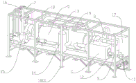
FIG. 1 is a schematic structural view of a vehicle-mounted mobile garbage anaerobic cracking treatment device of the present invention;
FIG. 2 is a schematic structural view of the vehicle-mounted mobile garbage anaerobic cracking treatment device of the present invention;
FIG. 3 is a schematic view of the process flow of the vehicle-mounted mobile anaerobic garbage cracking treatment device.
The reference numerals are explained below:
1. a tipping bucket feeding machine; 2. a hopper; 3. a constant feeder; 4. a chute is arranged; 5. a rotary cracking furnace; 6. water-cooling the slag extractor; 7. a collection box; 8. a cyclone dust collector; 9. a high temperature filter; 10. a gas induced draft fan; 11. burning a hot blast stove; 12. a combustion engine; 13. an air heat exchanger; 14. a spray tower; 15. a flue gas induced draft fan; 16. a chimney; 17. a control cabinet; 18. a frame; 1801. a support; 19. a combustion-supporting fan.
Detailed Description
The present invention will be further explained with reference to the accompanying drawings:
as shown in fig. 1-3, a tipping bucket feeding machine 1 is fixed on the short edge of one side of a frame 18 through bolts, a rotary cracking furnace 5 is fixed in the middle of the inner side of the frame 18 through bolts, a lower chute 4 is fixed on the feed side of the rotary cracking furnace 5 through bolts, a constant feeder 3 is fixed on the lower chute 4 through bolts, a hopper 2 is fixed on the constant feeder 3 through bolts, a water-cooling slag extractor 6 and a cyclone dust collector 8 are connected on the discharge side of the rotary cracking furnace 5 through pipelines, a collecting box fixed on the frame 18 is arranged on the outlet side of the water-cooling slag extractor 6, a high temperature filter 9 is connected on the outlet of the cyclone dust collector 8 through a pipeline, the high temperature filter 9 is connected to a combustion hot blast stove 11 through a gas induced draft fan 10 and a pipeline, a combustion machine 12 is welded on the combustion hot blast stove 11, the outlet of the combustion hot blast stove 11 is connected to the air inlet of the rotary, the flue gas outlet of the air heat exchanger 13 is connected to the spray tower 14 through a pipeline, the spray tower 14 is connected with a flue gas induced draft fan 15 through a pipeline, a chimney 16 is welded on the flue gas induced draft fan 15, the air outlet of the air heat exchanger 13 is connected to an air inlet of the combustion hot blast stove 11 through a combustion fan 19 and a pipeline, the air heat exchanger 13 is fixed at the top of the inner side of the frame 18 through bolts, a control cabinet 17 is fixed on one side of the inside of the frame 18 through bolts, the control cabinet 17 is electrically connected with electrical elements of the system, control and power supply of each electrical element are realized, and a support 1801 is.
When the rotary cracking furnace works, garbage is conveyed into a hopper 2 through a feeding tipping machine 1, the garbage in the hopper 2 is conveyed to a lower chute 4 through a double-roller type constant feeder 3, and finally enters an inner cylinder of a rotary cracking furnace 5 through the lower chute 4;
flue gas generated by a combustion hot blast stove 11 heats garbage in an inner cylinder of a rotary cracking furnace 5 through an outer cylinder of the rotary cracking furnace 5, the garbage moves forwards along with the rotation and uniform heating of the inner cylinder of the rotary cracking furnace 5, the reaction temperature of the rotary cracking furnace 5 is about 500 ℃, pyrolysis gas generated after pyrolysis enters a cyclone dust collector 8, and the pyrolysis gas is CO and H2、CO2、CH4、H2The ash slag which can not be cracked enters a water-cooled slag extractor 6 and then is sent to an ash slag collecting box 7;
pyrolysis gas removes dust through cyclone 8 earlier, the dust of collection sends into ash collecting box 7, then deacidify and further remove dust through high temperature filter 9 again, send into burning hot-blast furnace 11 by gas draught fan 10 at last, the air after preheating through air heat exchanger 13 simultaneously sends into burning hot-blast furnace 11 through combustion fan 19, with the pyrolysis gas burning generation high temperature flue gas in burning hot-blast furnace 11, then high temperature flue gas gets into 5 urceolus of gyration pyrolysis furnace and gives the material heating, the temperature of high temperature flue gas is 700 + 900 ℃.
After the flue gas is heated in the rotary cracking furnace 5, the flue gas enters the air heat exchanger 13 to preheat combustion air, the flue gas is cooled, then the flue gas enters the spray tower 14, spray water in the spray tower 14 is prepared alkaline water, acid gas in the flue gas can be removed, the flue gas is dedusted and cooled when the flue gas is introduced, and the flue gas after being cooled and purified to reach the standard is finally sent to the chimney 16 through the flue gas induced draft fan 15 to be discharged outwards.
The foregoing illustrates and describes the principles, general features, and advantages of the present invention. It will be understood by those skilled in the art that the present invention is not limited to the above embodiments, and that the foregoing embodiments and descriptions are provided only to illustrate the principles of the present invention without departing from the spirit and scope of the present invention. The scope of the invention is defined by the appended claims and equivalents thereof.
Claims (4)
1. The utility model provides a vehicle-mounted portable rubbish anaerobic cracking processing device which characterized in that: the device comprises a frame, a feeding device, an anaerobic rotary kiln cracking device, an ash treatment device, a cracked gas purification, combustion and heat supply integrated device and a flue gas cooling and purifying device, wherein a support is welded on a strut at the bottom of the frame, and the feeding device is arranged at the short edge of one side of the frame;
the feeding device comprises a tipping bucket feeding machine, a hopper connected with the upper part of the tipping bucket feeding machine, a constant feeder connected with the bottom of the hopper through a bolt, and a lower chute connected with the lower part of the constant feeder through a bolt, wherein the constant feeder adopts a double-roller feeding mode, the tipping bucket feeding machine fixes a tipping bucket on the outer side of the frame through a mounting bracket, and the tipping bucket feeding machine is powered by chain transmission driven by a motor; the oxygen-free rotary kiln cracking device is arranged on the inner side of the frame and adjacent to the feeding device;
the anaerobic rotary kiln cracking device comprises a rotary cracking furnace, wherein the feed end of the rotary cracking furnace is fixedly connected with the tail end of the lower chute through bolts, the slag outlet of the rotary cracking furnace is connected with a water-cooled slag extractor through a pipeline, the heating flue gas inlet of the rotary cracking furnace is connected with the outlet of a hot air furnace for combustion through a high temperature resistant pipeline, and the heating flue gas outlet of the rotary cracking furnace is connected with the heating flue gas inlet of an air heat exchanger through a high temperature resistant pipeline; the rotary cracking furnace is a double-barrel rotary furnace, materials are filled in an inner barrel of the rotary cracking furnace, high-temperature flue gas is introduced into an outer barrel of the rotary cracking furnace, the cracking temperature is 300-600 ℃, and the flue gas temperature is 700-900 ℃; an ash outlet of the rotary cracking furnace is connected with the ash treatment device; the gas outlet of the rotary cracking furnace is connected with the cracking gas purification device;
the ash residue treatment device comprises the water-cooling slag extractor and a collection box connected with the water-cooling slag extractor through a pipeline, and the water-cooling slag extractor cools ash residues in a water-cooling indirect heat exchange mode;
the pyrolysis gas purification, combustion and heat supply integrated device comprises a cyclone dust collector, a high-temperature filter, a gas induced draft fan, a burner and the combustion hot blast stove, wherein the inlet of the cyclone dust collector is connected with the pyrolysis gas outlet of the rotary cracking furnace through a pipeline, the outlet of the cyclone dust collector is connected with the inlet of the high-temperature filter through a pipeline, the outlet of the high-temperature filter is connected with the inlet of the gas induced draft fan through a pipeline, the outlet of the gas induced draft fan is connected with the gas inlet of the combustion hot blast stove through a pipeline, the air inlet of the combustion hot blast stove is connected with the outlet of a combustion fan fixed on the air heat exchanger through a pipeline, the air heat exchanger is fixed at the top of the inner side of the frame through bolts, and the air inlet of the combustion fan is fixed with the air outlet, the outlet of the combustion hot blast stove is connected with the flue gas inlet of the air heat exchanger through a pipeline, and the combustion machine is welded on the combustion hot blast stove through a mounting plate;
a control cabinet fixed on the frame through bolts is arranged beside the high-temperature filter, and a flue gas cooling and purifying device is arranged at the inner side of the frame and adjacent to the anaerobic cracking device;
the flue gas cooling and purifying device comprises an air heat exchanger, a spray tower, a flue gas induced draft fan and a chimney, wherein a flue gas outlet of the air heat exchanger is connected with a flue gas inlet of the spray tower through a pipeline, the flue gas inlet of the spray tower is connected with the flue gas induced draft fan through a pipeline, and the chimney is welded on the flue gas induced draft fan.
2. The vehicle-mounted movable anaerobic garbage cracking treatment device of claim 1, which is characterized in that: the support is a rectangular steel plate, and 2-4 symmetrically arranged mounting holes are formed in the support.
3. The vehicle-mounted movable anaerobic garbage cracking treatment device of claim 1, which is characterized in that: chute top and tail end set up to the flange down, chute lower part is closing in formula inverted pyramid structure down, install on the chute down and prevent blockking up automatic stoker.
4. The vehicle-mounted movable anaerobic garbage cracking treatment device of claim 1, which is characterized in that: the air heat exchanger is characterized in that 4-8 air inlets are arranged, each air inlet is provided with an axial flow fan, air is fed from the side face through the axial flow fan, and the inside of the air heat exchanger is divided into an air pipeline and a heating pipeline wrapping the air pipeline.
Priority Applications (1)
| Application Number | Priority Date | Filing Date | Title |
|---|---|---|---|
| CN201920148164.7U CN210035509U (en) | 2019-01-28 | 2019-01-28 | Vehicle-mounted movable anaerobic garbage cracking treatment device |
Applications Claiming Priority (1)
| Application Number | Priority Date | Filing Date | Title |
|---|---|---|---|
| CN201920148164.7U CN210035509U (en) | 2019-01-28 | 2019-01-28 | Vehicle-mounted movable anaerobic garbage cracking treatment device |
Publications (1)
| Publication Number | Publication Date |
|---|---|
| CN210035509U true CN210035509U (en) | 2020-02-07 |
Family
ID=69352552
Family Applications (1)
| Application Number | Title | Priority Date | Filing Date |
|---|---|---|---|
| CN201920148164.7U Active CN210035509U (en) | 2019-01-28 | 2019-01-28 | Vehicle-mounted movable anaerobic garbage cracking treatment device |
Country Status (1)
| Country | Link |
|---|---|
| CN (1) | CN210035509U (en) |
Cited By (1)
| Publication number | Priority date | Publication date | Assignee | Title |
|---|---|---|---|---|
| CN109764336A (en) * | 2019-01-28 | 2019-05-17 | 广州维港环保科技有限公司 | A kind of vehicle-mounted removable rubbish anaerobic cracking treatment system and method |
-
2019
- 2019-01-28 CN CN201920148164.7U patent/CN210035509U/en active Active
Cited By (1)
| Publication number | Priority date | Publication date | Assignee | Title |
|---|---|---|---|---|
| CN109764336A (en) * | 2019-01-28 | 2019-05-17 | 广州维港环保科技有限公司 | A kind of vehicle-mounted removable rubbish anaerobic cracking treatment system and method |
Similar Documents
| Publication | Publication Date | Title |
|---|---|---|
| CN203791331U (en) | System for synergistic treatment of municipal domestic waste in cement kiln | |
| CN102607033A (en) | Domestic garbage gasifying and melting incineration system and incineration method thereof | |
| CN107699294B (en) | Green island type urban and rural organic waste harmless recycling treatment process | |
| CN102012032A (en) | Medical waste complete incineration device | |
| CN112856432A (en) | Vortex self-heating type low-temperature dioxin detoxification device and detoxification system | |
| CN107676789A (en) | A kind of refuse pyrolysis method and device | |
| CN101476730A (en) | Energy-saving rubbish and dangerous waste incineration processing method | |
| CN210035509U (en) | Vehicle-mounted movable anaerobic garbage cracking treatment device | |
| CN106082571A (en) | Low heat value mud three change processes technique and device | |
| CN109764336A (en) | A kind of vehicle-mounted removable rubbish anaerobic cracking treatment system and method | |
| CN202501480U (en) | Domestic garbage gasification and melting incineration system | |
| CN211255815U (en) | Small cabinet type garbage low-temperature pyrolysis system | |
| CN210176803U (en) | Solid waste gasification melting system | |
| CN110699124A (en) | Method and system for organic solid waste gasification melting harmless treatment | |
| CN110762535A (en) | Method and system for harmless treatment of incineration and melting of organic solid wastes | |
| CN208869480U (en) | A kind of process system of industrial sludge cracking | |
| CN203036646U (en) | Incineration disposal system of oily sludge | |
| CN210826081U (en) | Double-bed pyrolysis gasification device for municipal domestic waste | |
| CN211345325U (en) | System for organic solid waste incineration melting innocent treatment | |
| CN213746746U (en) | Harmless treatment equipment for hazardous waste | |
| CN211170607U (en) | System for organic solid waste gasification melting innocent treatment | |
| CN210320063U (en) | Carbonization incinerator for treating solid waste material | |
| CN204022755U (en) | With the refuse disposal system of generating set | |
| CN112355033A (en) | High-temperature melting system of thermal plasma torch | |
| CN101516536B (en) | A deposited industrial waste thermodecomposition apparatus and decomposition method using thereof |
Legal Events
| Date | Code | Title | Description |
|---|---|---|---|
| GR01 | Patent grant | ||
| GR01 | Patent grant |