A kind of full-automatic superhard metal annular sawing machine
Technical field
The utility model relates to a kind of full-automatic superhard metal annular sawing machine.
Background technology
In prior art, for heavy, superhard metal bar, while adopting conventional metal annular sawing machine to cut, due to factors such as saw blade cutting machine speed are slow, cutting force is large, easily there is the problems such as burr, round edge, overlap, water chestnut oblique angle in cut surface, so not only smoothness and the sawing precision of the cut work piece cut face of impact, also can cause blade wear, reduces production efficiency; And circular sawing machine when work, conventionally be all hand operating mechanism, vibration and noise are larger, when the workpiece of different cross section and different length is cut, often to adopt the cutting machine of different size to produce or machinery debugging, can not branched while continuous saw cutting when sawing, affected production efficiency and economic benefit.
In addition, when the material of sawing different cross section, also to customize different fixtures, thereby increase production cost, for different processing lengths, can not realize any conversion, and operating cumbersomely, complex structure, during simultaneously for steel that phosphorus content is high or hardness is different such as heavy duty metal bar matter, sawing difficulty has certain requirement, if use general metal annular sawing machine, may cause the danger in cutting process, also do not have the product that can address these problems to occur at present.
Utility model content
The purpose of this utility model is to provide a kind of full-automatic superhard metal annular sawing machine, automatically completes feeding, lifts material, the process such as material folding, sawing, advance and retreat cutter, discharging, chip removal can branched continuous cutting-off, to overcome prior art above shortcomings.
The purpose of this utility model is to be achieved through the following technical solutions:
A kind of full-automatic superhard metal annular sawing machine, comprise main frame, material-preparing machine and Scrap-removing machine, the discharging opening of material-preparing machine is connected with the charging aperture of main frame, Scrap-removing machine is connected with main frame, main frame comprises fuselage, underbelly is provided with base, and base top is provided with to send lifts materials device, material feed clamping device, frame head apparatus, advance and retreat knife system and drawing mechanism, and fuselage outside is provided with control cabinet, control panel, relay indicating light and discharging opening.
Further, send act materials device to be fixed on base, send act materials device to comprise pay-off, clamping device and act materials device, pay-off comprises front jocket wheel, rear guide wheel and charging screw mandrel, charging screw mandrel is connected with motor by synchronizing wheel, and clamping device comprises stationary clamp, adjustable cramp and material folding oil cylinder, and adjustable cramp is connected with material folding oil cylinder, lift materials device and comprise act flitch, upper act oil cylinder and back-moving spring, lift flitch and be connected with back-moving spring with upper act oil cylinder respectively.
Further, material feed clamping device is positioned at frame and the main frame junction of material-preparing machine.
Further, frame head apparatus is fixed on base by fixed axis and two bearing blocks, is provided with motor, gear-box and saw blade in frame head apparatus, and motor is connected with the power shaft of gear-box, saw blade is connected with the output shaft of gear-box, and frame head apparatus is provided with magnetic powder brake device and blade shroud.
Further, advance and retreat knife system is fixed on base, and frame head apparatus is connected on advance and retreat knife system, and advance and retreat knife system comprises servo motor, synchronizing wheel and ball screw, and servo motor is all connected with synchronizing wheel with ball screw.
Further, drawing mechanism comprises discharging opening and the discharging differentiation plate that is arranged on discharging opening middle part, and the discharging opening right side is provided with discharging and regulates oil cylinder.
Further, material-preparing machine comprises frame, Lifting Device and micromatic setting, Lifting Device comprises power transmission shaft and die pad, in die pad, be vertically penetrated with guide pillar, guide pillar is fixed in frame, and a side of die pad is vertically provided with tooth bar, tooth bar is engaged with gear, gear is fixedly connected on one end of power transmission shaft, and die pad is connected with hydraulic jack, and micromatic setting is positioned at a side of frame.
Further, the fixed axis of frame head apparatus partly comprises main shaft, self-lubricating bearing and plane bearing, and self-lubricating bearing and plane bearing are installed on main shaft, is arranged with two groups of self-lubricating bearings and plane bearing on main shaft, and plane bearing is positioned at the outside of self-lubricating bearing.
Further, in gear-box, be provided with power shaft, driven shaft, clutch shaft and output shaft, power shaft is provided with input shaft gear, driven shaft is provided with driven gear one and driven gear two, the outside that is positioned at driven gear two on driven shaft is provided with buffer gear cold, clutch shaft is provided with clutch shaft gear, and output shaft is provided with output shaft gear; Input shaft gear and driven gear one, driven gear two mesh respectively with output shaft gear, output shaft gear and clutch shaft gear.
The beneficial effects of the utility model are: complete machine adopts total formation of the mechanisms such as touch screen control, servomotor, ball-screw, hydraulic system, can automatically complete feeding, lift the processes such as material, material folding, sawing, advance and retreat cutter, discharging, chip removal, each moving part of complete machine is equipped with automatic lubricating system, easy maintenance, raise the efficiency, reduce secondary operations, reduce costs and safety and environmental protection, product sawing precision is high, feed is steadily even, and noise is low, shakes little, can branched continuous cutting-off, greatly improve client's productivity effect.
Accompanying drawing explanation
With reference to the accompanying drawings the utility model is described in further detail below.
Fig. 1 is the overall structure schematic diagram of the full-automatic superhard metal annular sawing machine of the utility model embodiment;
Fig. 2 is the main frame external structure schematic diagram of the full-automatic superhard metal annular sawing machine of the utility model embodiment;
Fig. 3 is the main frame internal structure schematic diagram one of the full-automatic superhard metal annular sawing machine of the utility model embodiment;
Fig. 4 is the main frame internal structure schematic diagram two of the full-automatic superhard metal annular sawing machine of the utility model embodiment;
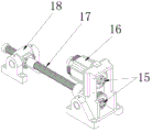
Fig. 5 is the advance and retreat knife system structural representation of the full-automatic superhard metal annular sawing machine of the utility model embodiment;
Fig. 6 is that sending of the full-automatic superhard metal annular sawing machine of the utility model embodiment lifted materials device structural representation;
Fig. 7 is the material-preparing machine structural representation of the full-automatic superhard metal annular sawing machine of the utility model embodiment;
Fig. 8 is the material-preparing machine partial structurtes schematic diagram of the full-automatic superhard metal annular sawing machine of the utility model embodiment;
Fig. 9 is the figure head fixed axle structure signal of the full-automatic superhard metal annular sawing machine of the utility model embodiment;
Figure 10 is the gear-box internal structure schematic diagram of the full-automatic superhard metal annular sawing machine of the utility model embodiment.
In figure:
1, main frame; 2, material-preparing machine; 3, Scrap-removing machine; 4, relay indicating light; 5, control panel; 6, control cabinet; 7, discharging opening; 8, frame head apparatus; 9, upper compressing cylinder; 10, advance and retreat knife system; 11, plate is differentiated in discharging; 12, discharging regulates oil cylinder; 13, base; 14, send act materials device; 15, synchronizing wheel; 16, servo motor; 17, ball screw; 18, feed screw nut; 19, adjustable cramp; 20, front jocket wheel; 21, guide rod; 22, rear guide wheel; 23, driven synchronizing wheel; 24, active synchronization wheel; 25, charging screw mandrel; 26, back-moving spring; 27, upper act oil cylinder; 28, lift flitch; 29, stationary clamp; 30, frame; 31, power transmission shaft; 32, micromatic setting; 33, Lifting Device; 34, die pad; 35, hydraulic jack; 36, tooth bar; 37, gear; 38, guide pillar; 39, main shaft; 40, self-lubricating bearing; 41, plane bearing; 42, input shaft gear; 43, driven gear two; 44, power shaft; 45, driven gear one; 46, driven shaft; 47, clutch shaft; 48, clutch shaft gear; 49, output shaft gear; 50, output shaft; 51, buffer gear cold.
The specific embodiment
As Figure 1-10 shows, a kind of full-automatic superhard metal annular sawing machine of the utility model embodiment, comprise main frame 1, material-preparing machine 2 and Scrap-removing machine 3, the discharging opening of material-preparing machine 2 is connected with the charging aperture of main frame 1, Scrap-removing machine 3 is connected with main frame 1, and main frame 1 comprises fuselage, and underbelly is provided with base 13, base 13 tops are provided with to send lifts materials device 14, clamping device, frame head apparatus 8, advance and retreat knife system 10 and drawing mechanism, and fuselage outside is provided with control cabinet 6, control panel 5, relay indicating light 4 and discharging opening 7.
Send act materials device 14 to be fixed on base 13, send act materials device 14 to comprise pay-off, clamping device and act materials device, pay-off comprises front jocket wheel 20, rear guide wheel 22 and charging screw mandrel 25, charging screw mandrel 25 is connected with motor by synchronizing wheel, clamping device comprises stationary clamp 29, adjustable cramp 19 and material folding oil cylinder, adjustable cramp 19 is connected with material folding oil cylinder, lift materials device and comprise act flitch 28, upper act oil cylinder 27 and back-moving spring 26, lift flitch 28 and be connected with back-moving spring 26 with upper act oil cylinder 27 respectively.
Material feed clamping device is positioned at the frame 30 of material-preparing machine 2 and the junction of main frame 1.
Frame head apparatus 8 is fixed on base 13 by fixed axis and two bearing blocks, frame head apparatus 8 is provided with motor, gear-box and saw blade, motor and belt pulley are connected with the power shaft 44 of gear-box, saw blade is connected with the output shaft 50 of gear-box, and the outside of frame head apparatus 8 is also provided with magnetic powder brake device and blade shroud.
Advance and retreat knife system 10 is fixed on base 13, and frame head apparatus 8 is connected on advance and retreat knife system 10, and advance and retreat knife system 10 comprises servo motor 16, synchronizing wheel 15 and ball screw 17, and servo motor 16 is all connected with synchronizing wheel 15 with ball screw 17.
Drawing mechanism comprises discharging opening 7 and the discharging differentiation plate 11 that is arranged on discharging opening 7 middle parts, and discharging opening 7 right sides are provided with discharging and regulate oil cylinder 12.
Material-preparing machine 2 comprises frame 30, Lifting Device 33 and micromatic setting 32, Lifting Device 33 comprises power transmission shaft 31 and die pad 34, the interior guide pillar 38 that is vertically penetrated with of die pad 34, guide pillar 38 is fixed in frame 30, one side of die pad 34 is vertically provided with tooth bar 36, and tooth bar 36 is engaged with gear 37, and gear 37 is fixedly connected on one end of power transmission shaft 31, die pad 34 is connected with hydraulic jack 35, and micromatic setting 32 is positioned at a side of frame 30.
The fixed axis of frame head apparatus 8 partly comprises main shaft 39, self-lubricating bearing 40 and plane bearing 41, self-lubricating bearing 40 and plane bearing 41 are installed on main shaft 39, on main shaft 39, be arranged with two groups of self-lubricating bearings 40 and plane bearing 41, plane bearing 41 is positioned at the outside of self-lubricating bearing 40.
In gear-box, be provided with power shaft 44, driven shaft 46, clutch shaft 47 and output shaft 50, power shaft 44 is provided with input shaft gear 42, driven shaft 46 is provided with driven gear 1 and driven gear 2 43, the outside that is positioned at driven gear 2 43 on driven shaft 46 is provided with buffer gear cold 51, clutch shaft 47 is provided with clutch shaft gear 48, and output shaft 50 is provided with output shaft gear 49; Input shaft gear 42 meshes respectively with clutch shaft gear 48 with output shaft gear 49, output shaft gear 49 with driven gear 1, driven gear 2 43.
Material-preparing machine 2 is auxiliary bodies that independently, complete automatic feed preparation, and micromatic setting 32 is mainly to carry out the spacing device of manual adjustments by material size.Material-preparing machine 2 is mainly carried out automatic feed preparation to cutting material; 1 pair of quilt of main frame is cut material and is implemented self-feeding, material folding, act material, automatic sawing, cutting automatic discrimination discharging, Scrap-removing machine 3 is to allow the sawdust producing after sawing automatically discharge, time and the manpower of sweeping iron filings have been saved, the personal injury that also can avoid so operate and produce.
Support is used for assembling main frame 1 each parts, main frame 1 protective cover adopts unique circular arc, right angle and oblique angle design, a plurality of observation windows can be multi-faceted the operating condition of observation main frame 1 inner each parts, the effect of discharge bucket is that the complete material of sawing is sent to main frame 1, and stub bar and finished product material are differentiated, isolated, control panel 5 is realized the operations to complete machine, comprise machine parameter setting, modification, move, stop etc.Operation and the halted state of relay indicating light 4 display devices.
Frame head apparatus 8 is rapidoprint to be carried out to the parts of sawing, by fixed axis and two bearing blocks, whole parts is fixed on support.Motor and drive pulley drive driven pulley, then by gear-box during by cutting required moment pass to saw blade, thereby rapidoprint is implemented to sawing.In sawing process, the relatively whole head of advance and retreat knife system 10 moves back and forth, and head is done oscillating motion centered by fixed axis, thereby realizes the object of automatic tool advancing and retracting.While adopting this equipment, the noise of complete machine is all smaller with vibrations, and user can adjust sawing and feed velocity on request voluntarily.
Advance and retreat knife system 10 is devices of realizing head automatic tool advancing and retracting, whole device by servo motor 16, synchronizing wheel 15 by transmission of power to ball screw 17, coordinate feed screw nut 18 and rear end bearing seat to do horizontal and move back and forth, thereby make head and saw blade realize horizontal advance and retreat cutter.This structure feed is steady, speed is even, and sawing face is level and smooth, indeformable, without burr.
Sending and lifting materials device 14 is automatically to complete feeding, clamp, lift the device of material, when machined material by material preparing rack, delivered to front jocket wheel 21 and after on guide wheel 22 after, servomotor drives synchronizing wheel 15, by charging screw mandrel 25, driven whole feeding again, material folding is moved and is return, the rear material folding oil cylinder that moved automatically by adjustable cramp 19, will be cut material and stationary clamp 29 clamps, again by upper act oil cylinder 27 by whole pay-off centered by guide rod 21, one-sided upper act 2-5MM, to guarantee that material surface does not produce friction with miscellaneous part and scratches in feeding process, then by servomotor, synchronizing wheel 15, screw mandrel, to be cut material and be delivered to head position.Complete after feeding, upper act oil cylinder 27 and back-moving spring 26 reset whole feeding part, and feeding and clamping oil cylinder, adjustable cramp 19 unclamp, and complete feeding, and return to reset, prepare next feeding.When material, automatically deliver to behind sawing position, clamping cylinder can be subject to oil pressure Automatic-clamping to be cut material, goes up compressing cylinder 9 simultaneously and from top, compresses material, makes head complete better more stably sawing action, improves sawing precision.
Lifting Device 33 is by preparing microscler bar on oblique frame and automatically head into the pay-off junction of main frame 1, replacing manpower to get the raw materials ready, simple and practical.
Head fixed axis is comprised of main shaft 39, self-lubricating bearing 40, plane bearing 41, bearing block, hubcap, and gear-box be take main shaft 39 and done swing feed campaign as fulcrum.Self-lubricating bearing 40 has reduced the radial friction between main shaft 39 and gear-box, and the effect of plane bearing 41 is: after main shaft 39, bearing block, hubcap are because of external force locking, gear-box still and between main shaft 39, keep going slick and without gap, left and right.Simple in structure, modern design.
Gear-box is comprised of several gears and bearing, power shaft 44, input shaft gear 42, driven gear, driven gear and output shaft gear 49 are for transmitting cutting moment and adjusting rotating speed, the effect of clutch gear is: when mechanical action is complete or people when stopping, exterior brake work, and reverse resistance is passed to output shaft gear 49, reach the object of slowing-down brake.The effect of buffer gear cold 51 is: because the running between gear exists necessary back lash, so gear can send sound or vibrations when initial engagement running, this buffer gear cold 51 designs in order to alleviate this deficiency.
The utility model complete machine adopts total formation of the mechanisms such as touch screen control, servomotor, ball-screw, hydraulic system, can automatically complete feeding, lift the processes such as material, material folding, sawing, advance and retreat cutter, discharging, chip removal, and each moving part of complete machine is equipped with automatic lubricating system, easy maintenance, raise the efficiency, reduce secondary operations, reduce costs and safety and environmental protection, product sawing precision is high, feed is steadily even, and noise is low, shakes little, can branched continuous cutting-off, greatly improve client's productivity effect.
Above-described embodiment is only for the utility model creation example is clearly described, and not the utility model is created the restriction of the specific embodiment.For those of ordinary skill in the field, can also make other changes in different forms on the basis of the above description.Here exhaustive without also giving all embodiments.All any apparent variations of being extended out within spirit of the present utility model and principle or change are still among the utility model is created the protection domain of claim.