CN203158098U - Front suspension device for commercial vehicle driving cab - Google Patents
Front suspension device for commercial vehicle driving cab Download PDFInfo
- Publication number
- CN203158098U CN203158098U CN 201320209638 CN201320209638U CN203158098U CN 203158098 U CN203158098 U CN 203158098U CN 201320209638 CN201320209638 CN 201320209638 CN 201320209638 U CN201320209638 U CN 201320209638U CN 203158098 U CN203158098 U CN 203158098U
- Authority
- CN
- China
- Prior art keywords
- shock absorber
- drum
- mounting seat
- type shock
- driving cab
- Prior art date
- Legal status (The legal status is an assumption and is not a legal conclusion. Google has not performed a legal analysis and makes no representation as to the accuracy of the status listed.)
- Expired - Fee Related
Links
Images
Abstract
The utility model provides a front suspension device for a commercial vehicle driving cab. The front suspension device comprises two corresponding mounting bases which are respectively fixed on a vehicle girder, a stable connecting rod is connected between the two mounting bases, and an overturning shaft is arranged behind each of the two mounting bases; an upper support frame is arranged on each overturning shaft; the outside face of each mounting base is provided and connected with a drum-type shock absorber by a pin shaft, a lower fixing end cover is sleeved outside each drum-type shock absorber, and is provided with a spiral spring sleeved outside the drum-type shock absorber, and the top end of each drum-type shock absorber is provided with a driving cab fixer, and an upper end cover is arranged between the driving cab fixer and the spiral spring; and an elastic limiting block is correspondingly arranged at the vehicle girder under the overturning shaft. The spiral spring and the drum-type shock absorber form a vibration isolation system to achieve the functions of buffering and damping the vibration transmitted on the upper end of a frame, thus improving the comfort level of a driving person, optimizing the structure of the suspension system, enhancing the strength of a longitudinal beam of the driving cab and reducing the broken risk of the longitudinal beam; and all indexes achieve project design requirements.
Description
Technical field
The utility model relates to the automobile cab field, specifically is the commercial-vehicle cab front hung holders.
Background technology
At present, domestic load-carrying vehicle Cab mounting can be divided into three kinds of modes substantially, namely traditional approach, 2 floated and 4 floated.Traditional Cab mounting mode is preceding trip shaft, back damping rubber block damping modes.The characteristics of this mode are simple in structure, easy to use; Shortcoming is that damping performance is poor.Simple in structure because of it, low price, be still at present domestic in the mode that mainly suspends of light-duty commercial vehicle/comm..vehicle.
2 suspensions mode front suspension that suspends adopts the trip shaft of rubber mount or band rubber coating, realizes essential suspension, vibration damping and guiding function.After suspend and adopt coil spring as elastic element, top links to each other with operator's compartment by portal frame, the bottom links to each other with vehicle frame by support, by guide groove and hydraulic lock channeling conduct.2 suspended pattern traveling comforts improve greatly than traditional approach, are mainly used on the medium and heavy automobile.This mode of suspending be the beginning of the eighties in last century domestic heavy goods vehicles manufacturing enterprise from external introduction, agingly gradually be about to withdraw from the market.The heavy motor vehicle suspension system is the kinematic scheme of a complexity, and Cab mounting also is the kinematic scheme of a complexity as the important component part of heavy motor vehicle suspension system.
4 suspended patterns generally comprise independently suspend before the operator's compartment and operator's compartment after suspend.Before left and right sides bearing, trip shaft (mainly being the inclination that reduces operator's compartment when turning), trip shaft left and right sides support assembly, the spiral damping spring (main effect is to bear vertical load and relax road shocks) etc. of suspending before comprising that suspend; After suspend and comprise left and right pillar, entablatrance, after cross member, operator's compartment lock, helical spring shock absorber (main effect is to bear vertical load and relax road shocks) etc., the suspend traveling comfort of mode of 4 suspensions has had large increase.
Suspend aspect the mode 4 suspensions and since at present both at home and abroad the lower operator's compartment of moving velocity adopt rigidity to suspend usually, it can produce strong vibrations when irregular road travels, pass to navigating mate.Especially at home the relatively poor area of some road conditions and when giving it the gun, this vibratory sensation is stronger, directly has influence on the driving safety of automobile, and is easy to generate driving fatigue, and safety is relatively poor.
Summary of the invention
The utility model improves safety and traveling comfort in order to reduce the vibrations of operator's compartment when irregular road travels, the special commercial-vehicle cab front hung holder that proposes.
The technical solution of the utility model is for this reason, the commercial-vehicle cab front hung holder comprises two corresponding mounting seat, and mounting seat is separately fixed on the automotive frame, be provided with stable pipe link between two mounting seat, the back of two mounting seat is provided with trip shaft; Trip shaft is provided with bracket; It is characterized in that: the lateral surface of mounting seat is connected with telescopic shock absorber by bearing pin, and telescopic shock absorber is with down fixedly end cap outward, and following fixed end covers and is provided with coil spring and is enclosed within outside the telescopic shock absorber, and the top of telescopic shock absorber is provided with the operator's compartment fixer; Be provided with fixedly end cap between operator's compartment fixer and the coil spring.
Improvement again to such scheme is: correspondence is provided with the elasticity limiting stopper on the automotive frame under the trip shaft.
Beneficial effect:
The utility model adopts coil spring to add telescopic shock absorber resistance element composition vibrating isolation system, can effectively play the vibration that transmit buffering and decay vehicle frame upper end, well improves comfort of drivers and passengers.By optimizing suspension system configuration, strengthened the intensity of operator's compartment longeron, reduce the risk of its fracture, every index has reached the Project design requirement.
The setting of elasticity limiting stopper is to play buffer action effectively when preventing the rigid landing of operator's compartment.
Description of drawings
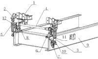
Fig. 1 is the utility model mounting structure scheme drawing.
1 is bracket among the figure, the 2nd, and the operator's compartment fixer, the 3rd, telescopic shock absorber, the 4th, stablize pipe link, 5 coil springs, 6 trip shafts, 7 mounting seat, 8 elasticity limiting stoppers, the 9th, automotive frame, the 10th, bearing pin, the 11st, following fixedly end cap, the 12nd, go up fixedly end cap.
The specific embodiment
The utility model as shown in Figure 1,
The commercial-vehicle cab front hung holder comprises two corresponding mounting seat 7, and mounting seat 7 is separately fixed on the automotive frame 9, is provided with the back of stablizing 4, two mounting seat 7 of pipe link between two mounting seat 7 and is provided with trip shaft 6; Trip shaft 6 is provided with bracket 1; The lateral surface of mounting seat 7 is connected with telescopic shock absorber 3 by bearing pin 10, the telescopic shock absorber 3 outer fixedly end caps 11 that are with down, fixedly end cap 11 is provided with coil spring 5 and is enclosed within outside the telescopic shock absorber 3 down, and the top of telescopic shock absorber 3 is provided with operator's compartment fixer 2; Be provided with fixedly end cap 12 between operator's compartment fixer 2 and the coil spring 5.
Correspondence is provided with elasticity limiting stopper 8 on the automotive frame 9 under the trip shaft 6.
The upper end of bracket 1 and operator's compartment fixer 2 are captiveed joint operator's compartment during use, by bottom bracket link trip shaft 6; Trip shaft 6 both sides link with mounting seat 7 respectively, mounting seat 7 uses bearing pin 10 and coil spring 5 and telescopic shock absorber 3 to couple together, telescopic shock absorber 3 is separate state with bracket 1 and stabilizer rod, telescopic shock absorber 3 is with mounting seat 7 that level is vertical puts, be 90 degree vertical direction with stable pipe link 4, install and more step up to urge, promote stability, enlarged cab space; Elasticity limiting device 8 is positioned at mounting seat 7 inboards, plays the fixedly effect of operator's compartment upper limit and lower limit.This technical scheme has used bracket 1 to be connected vehicle body with vehicle body fixer 2 stablizing pipe link 4 upsides simultaneously, makes the operator's compartment stabilizing power increase, and reduces the impact sense that commercial vehicle/comm..vehicle jolts and brings chaufeur when travelling.
Claims (2)
1. the commercial-vehicle cab front hung holder comprises two corresponding mounting seat, and mounting seat is separately fixed on the automotive frame, is provided with stable pipe link between two mounting seat, and the back of two mounting seat is provided with trip shaft; Trip shaft is provided with bracket; It is characterized in that: the lateral surface of mounting seat is connected with telescopic shock absorber by bearing pin, and telescopic shock absorber is with down fixedly end cap outward, and following fixed end covers and is provided with coil spring and is enclosed within outside the telescopic shock absorber, and the top of telescopic shock absorber is provided with the operator's compartment fixer; Be provided with fixedly end cap between operator's compartment fixer and the coil spring.
2.
According to claim 1The commercial-vehicle cab front hung holder is characterized in that: correspondence is provided with the elasticity limiting stopper on the automotive frame under the trip shaft.
Priority Applications (1)
| Application Number | Priority Date | Filing Date | Title |
|---|---|---|---|
| CN 201320209638 CN203158098U (en) | 2013-04-24 | 2013-04-24 | Front suspension device for commercial vehicle driving cab |
Applications Claiming Priority (1)
| Application Number | Priority Date | Filing Date | Title |
|---|---|---|---|
| CN 201320209638 CN203158098U (en) | 2013-04-24 | 2013-04-24 | Front suspension device for commercial vehicle driving cab |
Publications (1)
| Publication Number | Publication Date |
|---|---|
| CN203158098U true CN203158098U (en) | 2013-08-28 |
Family
ID=49019307
Family Applications (1)
| Application Number | Title | Priority Date | Filing Date |
|---|---|---|---|
| CN 201320209638 Expired - Fee Related CN203158098U (en) | 2013-04-24 | 2013-04-24 | Front suspension device for commercial vehicle driving cab |
Country Status (1)
| Country | Link |
|---|---|
| CN (1) | CN203158098U (en) |
Cited By (2)
| Publication number | Priority date | Publication date | Assignee | Title |
|---|---|---|---|---|
| CN108131564A (en) * | 2018-01-30 | 2018-06-08 | 张家港市华地机械装备有限公司 | The damping type braced frame of Vehicular liquefied natural gas cylinder |
| CN113184066A (en) * | 2021-06-21 | 2021-07-30 | 三一重机有限公司 | Front turning device of cab |
-
2013
- 2013-04-24 CN CN 201320209638 patent/CN203158098U/en not_active Expired - Fee Related
Cited By (3)
| Publication number | Priority date | Publication date | Assignee | Title |
|---|---|---|---|---|
| CN108131564A (en) * | 2018-01-30 | 2018-06-08 | 张家港市华地机械装备有限公司 | The damping type braced frame of Vehicular liquefied natural gas cylinder |
| CN113184066A (en) * | 2021-06-21 | 2021-07-30 | 三一重机有限公司 | Front turning device of cab |
| CN113184066B (en) * | 2021-06-21 | 2022-09-30 | 三一重机有限公司 | Front turning device of cab |
Similar Documents
| Publication | Publication Date | Title |
|---|---|---|
| CN206201894U (en) | A kind of shockproof vehicle suspension | |
| CN210191656U (en) | Commercial truck cab rear suspension system and vehicle | |
| CN203401898U (en) | Automobile rear independent suspension | |
| CN201961398U (en) | Front suspension device with variable rigidity | |
| CN203158098U (en) | Front suspension device for commercial vehicle driving cab | |
| CN208615670U (en) | A kind of suspension frame structure of vehicle chassis | |
| CN204432281U (en) | Deriving holds an independent suspension more | |
| CN203974460U (en) | A kind of caravan independent suspension device | |
| CN205113493U (en) | Torsional spring hangs mechanism with spring combination absorbing zhi chong | |
| CN106347060A (en) | Balanced suspension and automobile | |
| CN202301732U (en) | Automotive shock absorber with shock resistance | |
| CN102358128A (en) | Front suspension assembly | |
| CN205292169U (en) | Electric motor car forward mounting system | |
| CN205553836U (en) | Suspension assembly for vehicle | |
| CN202213463U (en) | Front suspension assembly | |
| CN201882153U (en) | Reinforcing structure of front shock absorber of automobile | |
| CN202186439U (en) | Front suspension device for cab | |
| CN203868234U (en) | Strengthened type vehicle shock absorber | |
| CN204726173U (en) | A kind of caravan independent suspension | |
| CN203996502U (en) | Multifunctional driver chamber suspension system | |
| CN103486174B (en) | A kind of damping spring | |
| CN202320327U (en) | Power chassis for heavy mining dumper | |
| CN214875182U (en) | Desert vehicle cab rear suspension damping device | |
| CN215041905U (en) | Independent suspension system of wheel | |
| CN105291744A (en) | Independent suspension device for touring car |
Legal Events
| Date | Code | Title | Description |
|---|---|---|---|
| C14 | Grant of patent or utility model | ||
| GR01 | Patent grant | ||
| CF01 | Termination of patent right due to non-payment of annual fee |
Granted publication date: 20130828 Termination date: 20160424 |
|
| CF01 | Termination of patent right due to non-payment of annual fee |