CN203051663U - Incomplete gear mechanism of mechanical arm - Google Patents

Incomplete gear mechanism of mechanical arm Download PDF

Info

Publication number
CN203051663U
CN203051663U CN201320016317.5U CN201320016317U CN203051663U CN 203051663 U CN203051663 U CN 203051663U CN 201320016317 U CN201320016317 U CN 201320016317U CN 203051663 U CN203051663 U CN 203051663U
Authority
CN
China
Prior art keywords
gear
cylindrical gears
incomplete
cylindrical
incomplete gear
Prior art date
Legal status (The legal status is an assumption and is not a legal conclusion. Google has not performed a legal analysis and makes no representation as to the accuracy of the status listed.)
Expired - Fee Related
Application number
CN201320016317.5U
Other languages
Chinese (zh)
Inventor
欧李苇
吴海涛
刘泓滨
温礼刚
Current Assignee (The listed assignees may be inaccurate. Google has not performed a legal analysis and makes no representation or warranty as to the accuracy of the list.)
Kunming University of Science and Technology
Original Assignee
Kunming University of Science and Technology
Priority date (The priority date is an assumption and is not a legal conclusion. Google has not performed a legal analysis and makes no representation as to the accuracy of the date listed.)
Filing date
Publication date
Application filed by Kunming University of Science and Technology filed Critical Kunming University of Science and Technology
Priority to CN201320016317.5U priority Critical patent/CN203051663U/en
Application granted granted Critical
Publication of CN203051663U publication Critical patent/CN203051663U/en
Anticipated expiration legal-status Critical
Expired - Fee Related legal-status Critical Current

Links

Images

Landscapes

  • Gear Transmission (AREA)

Abstract

本实用新型涉及一种机械手的不完全齿轮机构,属于机械设备齿轮传动设计和齿轮技术领域。本实用新型包括圆柱齿轮Ⅰ、不完全齿轮Ⅰ、从动齿轮、不完全齿轮Ⅱ、齿轮轴、圆柱齿轮Ⅱ;不完全齿轮Ⅰ通过齿轮轴安装在圆柱齿轮Ⅰ上,不完全齿轮Ⅱ通过齿轮轴安装在圆柱齿轮Ⅱ上,圆柱齿轮Ⅰ与圆柱齿轮Ⅱ啮合,从动齿轮安装在不完全齿轮Ⅰ与不完全齿轮Ⅱ中间、并与不完全齿轮Ⅰ啮合。本实用新型可实现机械手停顿需要、来回送放料工艺动作,机构结构简单,易于实现。

Figure 201320016317

The utility model relates to an incomplete gear mechanism of a manipulator, which belongs to the technical field of gear transmission design of mechanical equipment and gears. The utility model comprises a cylindrical gear I, an incomplete gear I, a driven gear, an incomplete gear II, a gear shaft and a cylindrical gear II; the incomplete gear I is installed on the cylindrical gear I through the gear shaft, and the incomplete gear II passes through the gear shaft Installed on the cylindrical gear II, the cylindrical gear I meshes with the cylindrical gear II, and the driven gear is installed between the incomplete gear I and the incomplete gear II, and meshes with the incomplete gear I. The utility model can realize the needs of the manipulator to stop, and the technological action of feeding and discharging back and forth, and the mechanism structure is simple and easy to realize.

Figure 201320016317

Description

A kind of intermittent gearing mechanism of mechanism hand
Technical field
The utility model relates to a kind of intermittent gearing mechanism of mechanism hand, belongs to machinery Gear Transmission Design and gear technique field.
Background technique
Intermittent gearing mechanism is a kind of intermittent motion mechanism, namely make a part of tooth at driving wheel, and make the gear teeth that are meshed with the driving wheel gear teeth according to run duration at follower with the requirement that rests, when the active crop rotation is turned round continuously, follower is done intermittent-rotation, and this mechanism structure is simple, easy to manufacture, reliable operation.At the veer away characteristics of motion of material of certain hot rammer material-extruding machine mechanism hand be: mechanism hand put after material folding, horizontal rotation, turn to utmost point position after, mechanism hand needs the time to pause to the lower swing blowing, puts on the arm behind the blowing, turns round in the other direction and treats material folding.Simple crankrocker mechanism or ratchet mechanism can't drive the material motion that veers away of mechanism hand that the above-mentioned characteristics of motion requires, and the realization of the technological action of feeding blowing is brought difficulty and inconvenience.
Summary of the invention
The purpose of this utility model provides a kind of intermittent gearing mechanism of mechanism hand, and the problem of free pause technological action is located in utmost point position in the time of can't realizing that to solve common crank rocker or ratchet mechanism mechanism hand veers away material.
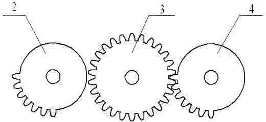
The utility model is realized by following technological scheme: a kind of intermittent gearing mechanism of mechanism hand comprises cylindrical gears I 1, partial gear I 2, driven gear 3, partial gear II 4, gear shaft 5, cylindrical gears II 6; Partial gear I 2 is installed on the cylindrical gears I 1 by gear shaft 5, partial gear II 4 is installed on the cylindrical gears II 6 by gear shaft 5, cylindrical gears I 1 is installed in the middle of partial gear I 2 and the partial gear II 4 and with partial gear I 2 and meshes with cylindrical gears II 6 engagements, driven gear 3.
A kind of working principle of intermittent gearing mechanism of mechanism hand is: motor is imported through being delivered on the cylindrical gears I 1 after the gear reduction step by step, cylindrical gears I 1 is rotated through gear shaft 5 and is delivered on the partial gear I 2, driving driven gear 3 rotates, cylindrical gears I 1 and 6 engagements of cylindrical gears II, so direction of rotation, then the direction of rotation of the sense of rotation of partial gear II 4 and partial gear I 2 can drive middle driven gear 3 and come back rotation.According to actual needs, radius by design partial gear and middle driven gear is realized different velocity ratios, and can design the number of teeth of partial gear, change the engagement time with intermediate gear, thereby reach mechanism hand in the time pause requirement at place, utmost point position.
The beneficial effect that the utlity model has is: can realize that the mechanism hand pause needs, the material technological action that veers away back and forth, mechanism structure is simple, is easy to realize.
Description of drawings
Fig. 1 is structural representation of the present utility model;
Fig. 2 is the utility model gear linkage structure schematic representation.
Each label is among the figure: 1: cylindrical gears I, 2: partial gear I, 3: driven gear, 4: partial gear II, 5: gear shaft, 6: the cylindrical gears II.
Embodiment
Below in conjunction with drawings and Examples, the utility model is described in further detail, but content of the present utility model is not limited to described scope.
Embodiment 1: shown in Fig. 1-2, a kind of intermittent gearing mechanism of mechanism hand comprises cylindrical gears I 1, partial gear I 2, driven gear 3, partial gear II 4, gear shaft 5, cylindrical gears II 6; Partial gear I 2 is installed on the cylindrical gears I 1 by gear shaft 5, partial gear II 4 is installed on the cylindrical gears II 6 by gear shaft 5, cylindrical gears I 1 and 6 engagements of cylindrical gears II, driven gear 3 are installed in partial gear I 2 and mesh in the middle of partial gear II 4 and with partial gear I 2.

Claims (1)

1. the intermittent gearing mechanism of a mechanism hand is characterized in that: comprise cylindrical gears I (1), partial gear I (2), driven gear (3), partial gear II (4), gear shaft (5), cylindrical gears II (6); Partial gear I (2) is installed on the cylindrical gears I (1) by gear shaft (5), partial gear II (4) is installed on the cylindrical gears II (6) by gear shaft (5), cylindrical gears I (1) and cylindrical gears II (6) engagement, driven gear (3) is installed in the middle of partial gear I (2) and the partial gear II (4) and with partial gear I (2) and meshes.
CN201320016317.5U 2013-01-14 2013-01-14 Incomplete gear mechanism of mechanical arm Expired - Fee Related CN203051663U (en)

Priority Applications (1)

Application Number Priority Date Filing Date Title
CN201320016317.5U CN203051663U (en) 2013-01-14 2013-01-14 Incomplete gear mechanism of mechanical arm

Applications Claiming Priority (1)

Application Number Priority Date Filing Date Title
CN201320016317.5U CN203051663U (en) 2013-01-14 2013-01-14 Incomplete gear mechanism of mechanical arm

Publications (1)

Publication Number Publication Date
CN203051663U true CN203051663U (en) 2013-07-10

Family

ID=48734619

Family Applications (1)

Application Number Title Priority Date Filing Date
CN201320016317.5U Expired - Fee Related CN203051663U (en) 2013-01-14 2013-01-14 Incomplete gear mechanism of mechanical arm

Country Status (1)

Country Link
CN (1) CN203051663U (en)

Cited By (5)

* Cited by examiner, † Cited by third party
Publication number Priority date Publication date Assignee Title
CN103807395A (en) * 2014-01-10 2014-05-21 平湖英厚机械有限公司 Gapless-alternating-motion gear mechanism
CN104400781A (en) * 2014-11-18 2015-03-11 河海大学常州校区 Material feeding manipulator
CN105443699A (en) * 2015-12-26 2016-03-30 郭嘉辉 Intermittent speed reducer
CN107950195A (en) * 2017-11-24 2018-04-24 西安科技大学 A kind of picking machine of incomplete gear mechanism transmission
CN109931375A (en) * 2019-03-05 2019-06-25 杭州天铭科技股份有限公司 Transmission device

Cited By (7)

* Cited by examiner, † Cited by third party
Publication number Priority date Publication date Assignee Title
CN103807395A (en) * 2014-01-10 2014-05-21 平湖英厚机械有限公司 Gapless-alternating-motion gear mechanism
CN104400781A (en) * 2014-11-18 2015-03-11 河海大学常州校区 Material feeding manipulator
CN104400781B (en) * 2014-11-18 2016-05-11 河海大学常州校区 Feeding mechanical hand
CN105443699A (en) * 2015-12-26 2016-03-30 郭嘉辉 Intermittent speed reducer
CN105443699B (en) * 2015-12-26 2018-03-27 盐城哈力动力传动及智能装备产业研究院有限公司 A kind of batch (-type) decelerator
CN107950195A (en) * 2017-11-24 2018-04-24 西安科技大学 A kind of picking machine of incomplete gear mechanism transmission
CN109931375A (en) * 2019-03-05 2019-06-25 杭州天铭科技股份有限公司 Transmission device

Similar Documents

Publication Publication Date Title
CN203051663U (en) Incomplete gear mechanism of mechanical arm
CN202690903U (en) Reversing device
CN104964013B (en) The transmission mechanism that a kind of single rotation direction input double rotational directions rotating is alternately exported
CN103026843A (en) Variable speed continuous box moving mechanism for transplanting pot seedlings
CN202326955U (en) Automatic forward and backward reverser
CN102720806A (en) One-way force transmission outputting reversing device driven by reciprocating force
CN203023404U (en) Two-way to one-way rotary transmission device
CN204828530U (en) Dan xuanxiang input bispin is to positive and negative drive mechanism who delivers for output
CN102804958A (en) Plug seedling taking mechanism with planetary gear trains of eccentric circular gears and non-circular gears
CN202228621U (en) Non-uniform speed intermittent transmission gear mechanism
CN202301786U (en) A multi-shaft synchronous transmission device
CN104315089B (en) Constant-speed transmission case of planetary gear train
CN104400781A (en) Material feeding manipulator
CN106424514A (en) Hot upsetting-extruding feeding manipulator
CN102434643A (en) Non-uniform speed intermittent transmission gear mechanism
CN202323309U (en) Roller right bracket of flat knitting machine
CN204321706U (en) Automatic tool change system and its power transmission device and reducer
CN203990780U (en) A kind of ball mill device for the production of foamed ceramic slurry
CN204327873U (en) Constant speed planetary gear train transmission case
CN203229619U (en) Unidirectional drive transmission mechanism with two servo motors for detaching rollers of combing machine
CN105570397A (en) Full ratchet gear wheel stepless speed change device
CN201621229U (en) Special speed changer for firecracker braiding machine
CN204868296U (en) Geared feed structure
CN204312628U (en) Speed reducer
CN202746505U (en) Position-changing bidirectional switching mechanism of gear with teeth difference

Legal Events

Date Code Title Description
C14 Grant of patent or utility model
GR01 Patent grant
CF01 Termination of patent right due to non-payment of annual fee

Granted publication date: 20130710

Termination date: 20150114

EXPY Termination of patent right or utility model