CN202947583U - Turbine casing position degree detecting device - Google Patents
Turbine casing position degree detecting device Download PDFInfo
- Publication number
- CN202947583U CN202947583U CN 201220608025 CN201220608025U CN202947583U CN 202947583 U CN202947583 U CN 202947583U CN 201220608025 CN201220608025 CN 201220608025 CN 201220608025 U CN201220608025 U CN 201220608025U CN 202947583 U CN202947583 U CN 202947583U
- Authority
- CN
- China
- Prior art keywords
- measuring
- base plate
- seat
- turbine case
- measured
- Prior art date
- Legal status (The legal status is an assumption and is not a legal conclusion. Google has not performed a legal analysis and makes no representation as to the accuracy of the status listed.)
- Expired - Fee Related
Links
Images


Landscapes
- Length Measuring Devices With Unspecified Measuring Means (AREA)
Abstract
The utility model provides a turbine casing position degree detecting device. The turbine casing position degree detecting device can improve detection efficiency, is suitable for a rapid detection link in the batch production process, reduces the using requirements for detection workers, and further reduces detection cost. The turbine casing position degree detecting device comprises a base plate, and bottom feet are installed at four corners of the base plate and are located on the bottom surface of the base plate. The turbine casing position degree detecting device is characterized by comprising a limiting structure and a position degree detection structure. The limiting structure and the position degree detection structure are vertically installed on the base plate. The position degree detection structure comprises a measuring base, a coarse locator, adjusting screws and a dial indicator measuring body. The measuring base is vertically installed on the base plate through a bolt and is respectively provided with two detecting through holes in a horizontal direction and a longitudinal direction, measuring sleeves are inserted into the detecting through holes, the coarse locator is installed on one side of the measuring base facing to a to-be-detected turbine casing, threaded holes are arranged below the measuring base and the coarse locator, the adjusting screws are installed in the threaded holes, the to-be-detected turbine casing is installed on the base plate through the limiting structure, and one end of an air outlet face of the to-be-detected turbine casing is towards the measuring base.
Description
Technical field
The utility model relates to supercharger turbo shell detection technique field, is specifically related to a kind of turbine case position detecting tool.
Background technology
The dimension control of tradition supercharger turbo shell position degree need adopt three-dimensional detection machine to test, measuring accuracy is high, can accurately measure the data deviation between element to be measured and drawing requirement, but Measuring Time is long, and detection efficiency is low, can't satisfy the fast detecting requirement in batch production process, high to testing staff's request for utilization simultaneously, need the system training through three-dimensional detection method and instrument use, could use, detect three-dimensional detection machine, testing cost be high.
Summary of the invention
For the problems referred to above, the utility model provides a kind of turbine case position detecting tool, and it can improve detection efficiency, is applicable to the fast detecting link in batch production process, and reduces the request for utilization to the testing staff, has further reduced testing cost.
its technical scheme is such, a kind of turbine case position detecting tool, it comprises base plate, be positioned at described base plate bottom surface, four jiaos of base plates are equipped with footing, it is characterized in that: it comprises position limiting structure and position degree detection architecture, described position limiting structure and described position degree detection architecture at right angle setting are in base plate, described position degree detection architecture comprises measuring seat, coarse positioning, set screw and clock gauge are measured body, described measuring seat passes through the bolt at right angle setting in described base plate, described measuring seat laterally and vertically respectively has two and detects through holes, described detection through-hole mounting has measuring unit, described coarse positioning is installed on described measuring seat towards turbine case one side to be detected, described measuring seat, described coarse positioning below is provided with threaded hole, described set screw is installed in threaded hole, described turbine case to be measured is installed on described base plate by position limiting structure, its face one end of giving vent to anger is towards described measuring seat.
It is further characterized in that:
described position limiting structure comprises reference seat, reference column and screw rod, described base plate, be positioned at described measuring seat one side and have datum hole, described reference seat at right angle setting is in described datum hole, described reference column at right angle setting is in described reference seat, described reference column and described reference seat center have connecting hole, described turbine case to be measured is positioned on described reference seat, its faying face is located by described reference column, described screw rod connects described turbine case to be measured successively, described reference column and described reference seat, described screw rod one end by pad and Bolt to position in the base plate bottom, described screw rod is positioned at turbine case one end clamping piece and fastening nuts turbine case to be measured to be measured,
described clock gauge is measured body and is comprised clock gauge, retaining sleeve, clamping ring, lengthen measuring staff and lengthen the measuring staff cover, described lengthening measuring staff cover has pilot hole along axis, described pilot hole one end is provided with step, described clock gauge measuring staff cover is installed on described lengthening measuring staff by retaining sleeve and overlaps its step, clamp with clamping ring between described clock gauge measuring staff cover and described retaining sleeve, described lengthening measuring staff is plugged in described lengthening measuring staff cover, described lengthening measuring staff cover, be positioned at perpendicular to its sidewall direction and have pilot hole, the corresponding pilot hole of described lengthening measuring staff has locating slot, described locating slot width is greater than described pilot hole internal diameter, be fitted with register pin in described pilot hole, described register pin one end inserts locating slot.
It further is characterised in that:
Described base plate and described reference seat have the pilot hole of connection, the corresponding turbine case bottom through-hole to be measured of described pilot hole, and locate with test pin.
after adopting the utility model structure, its beneficial effect is: during detection, the turbine case faying face is positioned on reference column, and locate with register pin, turbine case is given vent to anger facing to measuring seat, recent face one end of turbine case clamping piece and fastening nuts, clock gauge measurement body is inserted in two holes that are positioned at the measuring seat longitudinal direction, if clock gauge is looked several inconsistent, regulate set screw, make it consistent, at this moment, the volute face of giving vent to anger keeps vertical with surface level, measure body at two holes insertion clock gauges of measuring seat horizontal direction again, if depending on several inconsistent, represent that the volute facial plane degree of giving vent to anger is bad, it uses and detects rapidly, has improved detection efficiency, be applicable to the quick test in volute batch machining process, and it is simple to operate, has reduced the request for utilization to the testing staff, has further reduced testing cost.
Description of drawings
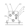
Fig. 1 is the utility model structural representation;
Fig. 2 is the utility model plan structure schematic diagram;
Fig. 3 is the left TV structure schematic diagram of the utility model measuring seat;
Fig. 4 is that in the utility model, clock gauge is measured the body structure schematic diagram.
Embodiment
see Fig. 1, Fig. 2, Fig. 3 and Fig. 4, a kind of turbine case position detecting tool, it comprises base plate 2, be positioned at base plate 2 bottom surfaces, four jiaos of base plates are equipped with footing 1, it comprises position limiting structure and position degree detection architecture, position limiting structure and position degree detection architecture at right angle setting are in base plate 2, the position degree detection architecture comprises measuring seat 3, coarse positioning 5, set screw 4 and clock gauge are measured body, measuring seat 3 passes through the bolt at right angle setting in base plate 2, measuring seat 3 laterally has two and detects through hole 21, 22, measuring seat 3 vertically has two and detects through hole 23, 24, detect through-hole mounting measuring unit 6 is arranged, coarse positioning 5 is installed on measuring seat 3 towards turbine case one side to be detected, measuring seat 3, coarse positioning below is provided with threaded hole, set screw 4 is installed in threaded hole, turbine case 13 to be measured is installed on base plate 2 by position limiting structure, its face one end of giving vent to anger is towards measuring seat 3,
position limiting structure comprises reference seat 8, reference column 11 and screw rod 20, base plate 2, be positioned at measuring seat 3 one sides and have datum hole, reference seat 8 at right angle settings are in datum hole, reference column 11 at right angle settings are in reference seat 8, reference column 11 and reference seat 8 centers have connecting hole, turbine case 13 to be measured is positioned on reference seat 8, its faying face is by reference column 11 location, screw rod 20 connects turbine case 13 to be measured successively, reference column 11 and reference seat 8, screw rod 20 1 ends by pad 12 with Bolt to position in the base plate bottom, screw rod 20 is positioned at turbine case 13 1 ends clamping piece 9 and the fastening turbine case 13 to be measured of nut 10 to be measured,
clock gauge is measured body and is comprised clock gauge 14, retaining sleeve 15, clamping ring 16, lengthen measuring staff 19 and lengthen measuring staff cover 17, lengthen measuring staff cover 17 and have pilot hole along axis, pilot hole one end is provided with step, clock gauge 14 measuring staff covers are installed on by retaining sleeve 15 and lengthen measuring staff cover 17 its steps, clamp with clamping ring 16 between clock gauge 14 measuring staff covers and retaining sleeve 15, lengthen measuring staff 19 and be plugged in lengthening measuring staff cover 17, lengthen measuring staff cover 17, be positioned at perpendicular to its sidewall direction and have pilot hole, lengthen the corresponding pilot hole of measuring staff 17 and have locating slot, the locating slot width is greater than the pilot hole internal diameter, be fitted with register pin 18 in pilot hole, register pin 18 1 ends insert locating slot,
Base plate 2 and reference seat 8 have the pilot hole of connection, corresponding turbine case 13 bottom through-holes to be measured of pilot hole, and locate with test pin 7.
Claims (4)
1. turbine case position detecting tool, it comprises base plate, be positioned at described base plate bottom surface, four jiaos of base plates are equipped with footing, it is characterized in that: it comprises position limiting structure and position degree detection architecture, described position limiting structure and described position degree detection architecture at right angle setting are in base plate, described position degree detection architecture comprises measuring seat, coarse positioning, set screw and clock gauge are measured body, described measuring seat passes through the bolt at right angle setting in described base plate, described measuring seat laterally and vertically respectively has two and detects through holes, described detection through-hole mounting has measuring unit, described coarse positioning is installed on described measuring seat towards turbine case one side to be detected, described measuring seat, described coarse positioning below is provided with threaded hole, described set screw is installed in threaded hole, described turbine case to be measured is installed on described base plate by position limiting structure, its face one end of giving vent to anger is towards described measuring seat.
2. a kind of turbine case position detecting tool according to claim 1, it is characterized in that: described position limiting structure comprises reference seat, reference column and screw rod, described base plate, be positioned at described measuring seat one side and have datum hole, described reference seat at right angle setting is in described datum hole, described reference column at right angle setting is in described reference seat, described reference column and described reference seat center have connecting hole, described turbine case to be measured is positioned on described reference seat, its faying face is located by described reference column, described screw rod connects described turbine case to be measured successively, described reference column and described reference seat, described screw rod one end by pad and Bolt to position in the base plate bottom, described screw rod is positioned at turbine case one end clamping piece and fastening nuts turbine case to be measured to be measured.
3. a kind of turbine case position detecting tool according to claim 1, it is characterized in that: described clock gauge is measured body and is comprised clock gauge, retaining sleeve, clamping ring, lengthen measuring staff and lengthen the measuring staff cover, described lengthening measuring staff cover has pilot hole along axis, described pilot hole one end is provided with step, described clock gauge measuring staff cover is installed on described lengthening measuring staff by retaining sleeve and overlaps its step, clamp with clamping ring between described clock gauge measuring staff cover and described retaining sleeve, described lengthening measuring staff is plugged in described lengthening measuring staff cover, described lengthening measuring staff cover, be positioned at perpendicular to its sidewall direction and have pilot hole, the corresponding pilot hole of described lengthening measuring staff has locating slot, described locating slot width is greater than described pilot hole internal diameter, be fitted with register pin in described pilot hole, described register pin one end inserts locating slot.
4. a kind of turbine case position detecting tool according to claim 2, it is characterized in that: described base plate and described reference seat have the pilot hole of connection, the corresponding turbine case bottom through-hole to be measured of described pilot hole, and locate with test pin.
Priority Applications (1)
| Application Number | Priority Date | Filing Date | Title |
|---|---|---|---|
| CN 201220608025 CN202947583U (en) | 2012-11-18 | 2012-11-18 | Turbine casing position degree detecting device |
Applications Claiming Priority (1)
| Application Number | Priority Date | Filing Date | Title |
|---|---|---|---|
| CN 201220608025 CN202947583U (en) | 2012-11-18 | 2012-11-18 | Turbine casing position degree detecting device |
Publications (1)
| Publication Number | Publication Date |
|---|---|
| CN202947583U true CN202947583U (en) | 2013-05-22 |
Family
ID=48423282
Family Applications (1)
| Application Number | Title | Priority Date | Filing Date |
|---|---|---|---|
| CN 201220608025 Expired - Fee Related CN202947583U (en) | 2012-11-18 | 2012-11-18 | Turbine casing position degree detecting device |
Country Status (1)
| Country | Link |
|---|---|
| CN (1) | CN202947583U (en) |
Cited By (2)
| Publication number | Priority date | Publication date | Assignee | Title |
|---|---|---|---|---|
| CN102980464A (en) * | 2012-11-18 | 2013-03-20 | 无锡麦铁精密机械制造有限公司 | Turbine shell location degree detection tool |
| CN107627153A (en) * | 2017-10-25 | 2018-01-26 | 东风设备制造有限公司 | Camshaft positions clamping end face gas check |
-
2012
- 2012-11-18 CN CN 201220608025 patent/CN202947583U/en not_active Expired - Fee Related
Cited By (3)
| Publication number | Priority date | Publication date | Assignee | Title |
|---|---|---|---|---|
| CN102980464A (en) * | 2012-11-18 | 2013-03-20 | 无锡麦铁精密机械制造有限公司 | Turbine shell location degree detection tool |
| CN107627153A (en) * | 2017-10-25 | 2018-01-26 | 东风设备制造有限公司 | Camshaft positions clamping end face gas check |
| CN107627153B (en) * | 2017-10-25 | 2024-01-09 | 东风设备制造有限公司 | End face gas detection device for positioning and clamping camshaft |
Similar Documents
| Publication | Publication Date | Title |
|---|---|---|
| CN102980464A (en) | Turbine shell location degree detection tool | |
| CN102967216A (en) | Steering connector position degree inspection device | |
| CN102607433B (en) | Multi-point detection device for thickness of bearing bush | |
| CN111872743B (en) | Device and method for detecting thermotropic straightness-verticality error of horizontal machining center | |
| CN102288083B (en) | Method and gauge for detecting true position of pump shell | |
| CN102967252B (en) | Connection bracket stationary plane planeness check tool | |
| CN102967211A (en) | Engine connecting bracket location degree detection measuring tool | |
| CN202002592U (en) | Middle case jumping checking tool | |
| CN202329505U (en) | Position error inspection jig | |
| CN202947583U (en) | Turbine casing position degree detecting device | |
| CN202734787U (en) | Co-plane degree inspection device for belt pulley series of engine | |
| CN103438842A (en) | Detecting device of engine cylinder cover holes | |
| CN203116688U (en) | Inspection tool for eccentric magnitude parallelism of eccentric bushing | |
| CN203572381U (en) | Integrated detector for turbine casing | |
| CN203893769U (en) | Steering device housing position accuracy testing gauge | |
| CN102980465A (en) | Position degree checking tool of motor back cover | |
| CN205664765U (en) | Detection apparatus for be used for auto parts shape face | |
| CN202947593U (en) | Engine connecting support position detection device | |
| CN203657643U (en) | Detection structure for flange member of automobile engine | |
| CN201885666U (en) | Surface shape calibrator | |
| CN206556537U (en) | Pipe fitting hole location detecting mechanism | |
| CN103398647B (en) | A kind of method for measuring point and cross section spacing on part | |
| CN202947581U (en) | Gauge for crankshaft end face connection hole location degree | |
| CN202947676U (en) | Gauge for connecting support fixing face planeness | |
| CN207180516U (en) | A kind of holes detects special gauge |
Legal Events
| Date | Code | Title | Description |
|---|---|---|---|
| C14 | Grant of patent or utility model | ||
| GR01 | Patent grant | ||
| C17 | Cessation of patent right | ||
| CF01 | Termination of patent right due to non-payment of annual fee |
Granted publication date: 20130522 Termination date: 20131118 |