CN202848530U - Precision connecting conveyor - Google Patents
Precision connecting conveyor Download PDFInfo
- Publication number
- CN202848530U CN202848530U CN 201220375286 CN201220375286U CN202848530U CN 202848530 U CN202848530 U CN 202848530U CN 201220375286 CN201220375286 CN 201220375286 CN 201220375286 U CN201220375286 U CN 201220375286U CN 202848530 U CN202848530 U CN 202848530U
- Authority
- CN
- China
- Prior art keywords
- chain
- precision
- wheel
- fixture block
- frame
- Prior art date
- Legal status (The legal status is an assumption and is not a legal conclusion. Google has not performed a legal analysis and makes no representation as to the accuracy of the status listed.)
- Expired - Fee Related
Links
Images

Abstract
The utility model discloses a precision connecting conveyor and belongs to the field of industrial conveyors. The precision connecting conveyor comprises a chain support. The precision connecting conveyor further comprises a supporting guide roller, a dividing wheel drove by a cam indexer and a chain connecting the supporting guide roller and the dividing wheel. The supporting guide roller is arranged at one end of the chain support through a transverse adjusting device and the dividing wheel is rotatablely arranged at the other end of the chain support. The chain is composed of a plurality of chain knots connected in a hinge mode through a chain shaft. The chain knots comprise a first connecting plate (7) and a second connecting plate, wherein the first connecting plate (7) and the second connecting plate are connected together in a hinge mode through the chain shaft. A fixture block is sleeved on the chain shaft and a plurality of card slots corresponding to the fixture block are arranged on the dividing wheel. The precision connecting conveyor is good in location accuracy, high in work efficiently and long in service life.
Description
Technical field
The utility model relates to a kind of accurate conveyer that connects, and belongs to industrial conveyer field.
Background technology
At present, existing conveyer adopts the conveyer of load-transfer device or conventional chain-type mostly.Adopt both that reducing motor drives, motorized pulleys drive the cooperative mechanical drive mechanism, such as mechanical types such as cam, worm screw, gear, sprocket wheels, the life-span that can cause the generation of extra heating, the common-mode voltage of motor, cable might reduce motor shaft.The conveyer belt type transmission, easy to wear, the phenomenon circulation has some setbacks clamping stagnation to occur easily, skid etc., transmits that precision and accuracy of positioning are poor to be not suitable for high-precision transmission demand.And it is because of the material problem, need to regularly change, and maintenance cost is high.The chain conveyor line is actual in relatively less in factory, its complex structure, and noise is large.Behind the wear of hinge of chain, cause obscission so that pitch becomes Da Yi, installation and maintenance requirement are higher.So a kind of belt conveyor of high-speed, high precision invention is that market and practical value are arranged very much, not only had been fit to product and has transmitted, but also make things convenient for product orientation processing.Possesses high reliability and permanent service life, the advantages such as less maintenance requirement (annual inspection and the adjustment that only need carry out the preload load of a chain), intensity high-wearing feature extendability good, each chain link can be carried arbitrarily tool fixture by force, and highly versatile, application are wide.
Summary of the invention
The purpose of this utility model is the defective that overcomes prior art, provides a kind of accuracy of positioning good, high efficiency, and the precision of long service life connects conveyer.
The technical scheme that realizes the utility model purpose is: a kind of accurate conveyer that connects, comprise the chain frame, also comprise and support guide wheel and be connected the divided wheel of cam protractor driving and the chain that connects support guide wheel and divided wheel, support guide wheel is installed in the chain frame by lateral adjustment a end, divided wheel is rotatably installed in the other end of chain frame, chain is comprised of by the hinged chain link of chain rivet some, chain link comprises by chain rivet hinged the first connecting panel 7 and the second connecting panel, be set with fixture block on the chain rivet, be provided with the draw-in groove that some cards are joined fixture block on the described divided wheel.
Further, described fixture block is bearing, the baffle plate with the bearing rolling groove is installed on the described chain frame, and baffle plate is positioned at the both sides of chain.
Further, the guide rail of supporting chain is installed on the described chain frame, the antifriction-bearing box that can roll in the guide rail side is installed on the described chain.
Further, be set with oilless metal at the position that contacts with the first connecting panel on the described chain rivet.
After having adopted technique scheme, frequency converter is controlled the gear motor rotation, the motor driving cam protractor, indexing attachment drives divided wheel and rotates, divided wheel drives the chain rotation, support guide wheel chain is played guiding, thereby reach the purpose of transmission, cam protractor is intermittent moment, has just in time met the needs of assembling line needs time of setting up, support guide wheel can also by lateral adjustment regulate support guide wheel away from or regulate its tension force near the chain frame, make chain tightens, in order to avoid chain-loose can load location or transmission that frock or tool carry out product on each chain link, thereby reach the purpose of conveying.The design of baffle plate or guide rail has prevented that the phenomenon of horizontal displacement from appearring in chain, makes transmitting ratio more continuous, reduces the phenomenon of stagnating midway; There is certain difficulty the position of chain of the present utility model so that chain is oily, and the use of oilless metal has just reduced the phenomenon of chain oiling, also can lubricate better, and working environment has also obtained further beautifying.
Description of drawings
Fig. 1 is the accurate block diagram that connects conveyer of the present utility model;
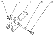
Fig. 2 is the three-dimensional broken away view of chain link of the present utility model.
The specific embodiment
Content of the present utility model is easier to be expressly understood in order to make, and the below is described in further detail the utility model according to specific embodiment also by reference to the accompanying drawings,
Such as Fig. 1, shown in 2, a kind of accurate conveyer that connects, comprise chain frame 1, also comprise and support guide wheel 2 and be connected the divided wheel 3 of cam protractor driving and the chain 4 that connects support guide wheel 2 and divided wheel 3, support guide wheel 2 is installed in chain frame 1 by lateral adjustment 5 a end, divided wheel 3 is rotatably installed in the other end of chain frame 1, chain 4 is comprised of by chain rivet 6 hinged chain links some, chain link comprises by chain rivet 6 hinged the first connecting panel 7 and the second connecting panel 8, be set with fixture block 9 on the chain rivet 6, be provided with the draw-in groove 3-1 that some cards are joined fixture block 9 on the described divided wheel 3.The both sides of chain frame 1 are equipped with feet assembly 14.
As shown in Figure 1, fixture block 9 is bearing, the baffle plate 10 with bearing rolling groove 10-1 is installed on the chain frame 1, and baffle plate 10 is positioned at the both sides of chain 4.
As shown in Figure 1, 2, the guide rail 11 of supporting chain 4 is installed on the chain frame 1, the antifriction-bearing box 12 that can roll in guide rail 11 sides is installed on the chain 4.
As shown in Figure 2, be set with oilless metal 13 at the position that contacts with the first connecting panel 7 on the chain rivet 6.
Principle of work of the present utility model is as follows:
Frequency converter is controlled the gear motor rotation, the motor driving cam protractor, cam protractor drives divided wheel 3 and rotates, divided wheel 3 drives chain 4 rotations, support 2 pairs of chains 4 of guide wheel and play guiding, thereby reach the purpose of transmission, cam protractor is intermittent moment, the needs that just in time met assembling line needs time of setting up, support guide wheel 2 can also by lateral adjustment 5 regulate support guide wheels 2 away from or regulate its tension force near chain frame 1, chain 4 is tightened, in order to avoid chain 4 is loosening, can load frock or tool on each chain link and carry out location or the transmission of product, thereby reach the purpose of conveying.The design of baffle plate 10 or guide rail 11 has prevented that the phenomenon of horizontal displacement from appearring in chain 4, makes transmitting ratio more continuous, reduces the phenomenon of stagnating midway; There is certain difficulty the position of chain 4 of the present utility model so that chain 4 is oily, and the use of oilless metal 13 has just reduced the phenomenon that chain 4 oils, and also can lubricate better, and working environment has also obtained further beautifying.
Above-described specific embodiment; the purpose of this utility model, technical scheme and beneficial effect are further described; institute is understood that; the above only is specific embodiment of the utility model; be not limited to the utility model; all within spirit of the present utility model and principle, any modification of making, be equal to replacement, improvement etc., all should be included within the protection domain of the present utility model.
Claims (4)
1. a precision connects conveyer, comprise chain frame (1), it is characterized in that: also comprise and support guide wheel (2) and be connected the divided wheel (3) of cam protractor driving and the chain (4) that connects support guide wheel (2) and divided wheel (3), support guide wheel (2) is installed in chain frame (1) by lateral adjustment (5) a end, divided wheel (3) is rotatably installed in the other end of chain frame (1), chain (4) is comprised of by the hinged chain link of chain rivet (6) some, chain link comprises by chain rivet (6) hinged the first connecting panel (7) and the second connecting panel (8), be set with fixture block (9) on the chain rivet (6), be provided with some cards on the described divided wheel (3) and join the draw-in groove of fixture block (9) (3-1).
2. precision according to claim 1 connects conveyer, it is characterized in that: described fixture block (9) is bearing, the baffle plate (10) of band bearing rolling groove (10-1) is installed on the described chain frame (1), and baffle plate (10) is positioned at the both sides of chain (4).
3. precision according to claim 1 and 2 connects conveyer, it is characterized in that: the guide rail (11) of supporting chain (4) is installed on the described chain frame (1), the antifriction-bearing box (12) that can roll in guide rail (11) side is installed on the described chain (4).
4. precision according to claim 1 and 2 connects conveyer, it is characterized in that: described chain rivet (6) is upper to be set with oilless metal (13) at the position that contacts with the first connecting panel (7).
Priority Applications (1)
| Application Number | Priority Date | Filing Date | Title |
|---|---|---|---|
| CN 201220375286 CN202848530U (en) | 2012-07-31 | 2012-07-31 | Precision connecting conveyor |
Applications Claiming Priority (1)
| Application Number | Priority Date | Filing Date | Title |
|---|---|---|---|
| CN 201220375286 CN202848530U (en) | 2012-07-31 | 2012-07-31 | Precision connecting conveyor |
Publications (1)
| Publication Number | Publication Date |
|---|---|
| CN202848530U true CN202848530U (en) | 2013-04-03 |
Family
ID=47979751
Family Applications (1)
| Application Number | Title | Priority Date | Filing Date |
|---|---|---|---|
| CN 201220375286 Expired - Fee Related CN202848530U (en) | 2012-07-31 | 2012-07-31 | Precision connecting conveyor |
Country Status (1)
| Country | Link |
|---|---|
| CN (1) | CN202848530U (en) |
Cited By (2)
| Publication number | Priority date | Publication date | Assignee | Title |
|---|---|---|---|---|
| CN106809599A (en) * | 2017-03-07 | 2017-06-09 | 苏州盖特龙自动化设备有限公司 | A kind of chain-type high speed and precision induction system |
| CN111620048A (en) * | 2020-06-03 | 2020-09-04 | 嘉善伟悦紧固件有限公司 | Feeding device is used in fastener production |
-
2012
- 2012-07-31 CN CN 201220375286 patent/CN202848530U/en not_active Expired - Fee Related
Cited By (4)
| Publication number | Priority date | Publication date | Assignee | Title |
|---|---|---|---|---|
| CN106809599A (en) * | 2017-03-07 | 2017-06-09 | 苏州盖特龙自动化设备有限公司 | A kind of chain-type high speed and precision induction system |
| CN106809599B (en) * | 2017-03-07 | 2023-08-15 | 苏州盖特龙自动化设备有限公司 | Chain type precise high-speed conveying system |
| CN111620048A (en) * | 2020-06-03 | 2020-09-04 | 嘉善伟悦紧固件有限公司 | Feeding device is used in fastener production |
| CN111620048B (en) * | 2020-06-03 | 2022-06-21 | 嘉善伟悦紧固件有限公司 | Feeding device is used in fastener production |
Similar Documents
| Publication | Publication Date | Title |
|---|---|---|
| CN207861344U (en) | A kind of novel jacking transferring machine | |
| CN205998511U (en) | A kind of wheel hub pipeline | |
| US20090266186A1 (en) | Ring Rack Oil Pumping Machine | |
| CN202481664U (en) | Plate chain conveyer | |
| CN106276077A (en) | A kind of double-chain conveyor | |
| CN201729478U (en) | Belt conveying mechanism | |
| CN106628918A (en) | Long-distance heavy-load dragging device | |
| CN202924356U (en) | Transitional lifting rolling machine | |
| CN104816921A (en) | Double side drive transport system | |
| CN202848530U (en) | Precision connecting conveyor | |
| CN201770272U (en) | Chain bed conveyor | |
| CN208699969U (en) | A kind of high speed shunting machine | |
| CN202924355U (en) | Rotary lifting rolling machine | |
| CN201145008Y (en) | Two-sided synchronous toothed belt drive device | |
| CN203889533U (en) | Linearly-driven roller conveying system | |
| CN203753779U (en) | PBT extra-heavy type ground plate chain conveyer | |
| CN205734799U (en) | A kind of synchronization intersection double-station device | |
| CN202717286U (en) | Transmission device of belt material conveying equipment | |
| CN214191327U (en) | Double-chain conveyor with variable width | |
| CN210133213U (en) | Intelligent transfer trolley | |
| CN206456905U (en) | A kind of heavily loaded actuator of long range | |
| CN109489416B (en) | In-out transfer machine for roller kiln | |
| CN205927275U (en) | Put dual drive structure in planer -type sheet metal keyway planer | |
| CN210527556U (en) | Rotary belt roller machine for tobacco conveying | |
| CN214568537U (en) | Conveying device with adjustable width |
Legal Events
| Date | Code | Title | Description |
|---|---|---|---|
| C14 | Grant of patent or utility model | ||
| GR01 | Patent grant | ||
| CF01 | Termination of patent right due to non-payment of annual fee |
Granted publication date: 20130403 Termination date: 20150731 |
|
| EXPY | Termination of patent right or utility model |