CN111620048A - Feeding device is used in fastener production - Google Patents
Feeding device is used in fastener production Download PDFInfo
- Publication number
- CN111620048A CN111620048A CN202010493910.3A CN202010493910A CN111620048A CN 111620048 A CN111620048 A CN 111620048A CN 202010493910 A CN202010493910 A CN 202010493910A CN 111620048 A CN111620048 A CN 111620048A
- Authority
- CN
- China
- Prior art keywords
- groove
- plate
- feeding device
- close
- fastener
- Prior art date
- Legal status (The legal status is an assumption and is not a legal conclusion. Google has not performed a legal analysis and makes no representation as to the accuracy of the status listed.)
- Granted
Links
Images


Classifications
-
- B—PERFORMING OPERATIONS; TRANSPORTING
- B65—CONVEYING; PACKING; STORING; HANDLING THIN OR FILAMENTARY MATERIAL
- B65G—TRANSPORT OR STORAGE DEVICES, e.g. CONVEYORS FOR LOADING OR TIPPING, SHOP CONVEYOR SYSTEMS OR PNEUMATIC TUBE CONVEYORS
- B65G17/00—Conveyors having an endless traction element, e.g. a chain, transmitting movement to a continuous or substantially-continuous load-carrying surface or to a series of individual load-carriers; Endless-chain conveyors in which the chains form the load-carrying surface
- B65G17/30—Details; Auxiliary devices
- B65G17/38—Chains or like traction elements; Connections between traction elements and load-carriers
- B65G17/40—Chains acting as load-carriers
-
- B—PERFORMING OPERATIONS; TRANSPORTING
- B65—CONVEYING; PACKING; STORING; HANDLING THIN OR FILAMENTARY MATERIAL
- B65G—TRANSPORT OR STORAGE DEVICES, e.g. CONVEYORS FOR LOADING OR TIPPING, SHOP CONVEYOR SYSTEMS OR PNEUMATIC TUBE CONVEYORS
- B65G17/00—Conveyors having an endless traction element, e.g. a chain, transmitting movement to a continuous or substantially-continuous load-carrying surface or to a series of individual load-carriers; Endless-chain conveyors in which the chains form the load-carrying surface
- B65G17/30—Details; Auxiliary devices
- B65G17/46—Means for holding or retaining the loads in fixed position on the load-carriers, e.g. magnetic
Abstract
The invention discloses a feeding device for fastener production, which comprises a chain plate and a fixed plate, wherein two ends of the chain plate are respectively provided with a lug, two sides of each lug are respectively provided with a transverse shaft, a bearing is sleeved on each transverse shaft, the outer side surface of each bearing is provided with a clamping groove, the upper end of the chain plate is provided with a placing groove, a limiting rod is arranged between the front end and the rear end of the placing groove and close to the side wall, a limiting plate is arranged between the front end and the rear end of the placing groove and close to the middle position, two groups of limiting rods are sleeved with a push plate, a collecting box is arranged between the rear end of the push plate and the side wall of the placing groove, a partition plate is arranged between the side walls of the collecting box and close to the middle position, the partition plate divides the. This loading attachment is used in fastener production can be convenient for the staff installation and dismantle the link joint, and the material loading of the former material of fastener is comparatively convenient.
Description
Technical Field
The invention relates to the field of fasteners, in particular to a feeding device for fastener production.
Background
The fastener is a mechanical part which is used for fastening connection and has wide application, has wide application industry, comprises the industries of energy, electronics, electrical appliances, machinery, chemical industry, metallurgy, molds, hydraulic pressure and the like, and has wide application on various machines, equipment, vehicles, ships, railways, bridges, buildings, structures, tools, instruments, chemical industry, instruments, supplies and the like; it is characterized by various varieties and specifications, various performance and purposes, and extremely high standardization, serialization and generalization degrees; thus, one type of fastener that also has national standards is known as a standard fastener, or simply a standard;
the feeding device for producing the fasteners on the market is mostly inconvenient for installing and disassembling chain plates, and feeding of raw materials of the fasteners is troublesome, so that the feeding device for producing the fasteners is provided.
Disclosure of Invention
The invention aims to provide a feeding device for producing fasteners, which aims to solve the problems that the feeding device for producing fasteners in the market proposed in the background art is inconvenient to mount and dismount chain plates and troublesome in feeding raw materials of the fasteners.
In order to achieve the purpose, the invention provides the following technical scheme: the utility model provides a loading attachment is used in fastener production, includes link joint and fixed plate, the link joint both ends all are provided with the lug, the lug both sides all are provided with the cross axle, the cover is equipped with the bearing on the cross axle, the draw-in groove has been seted up on the bearing lateral surface, the standing groove has been seted up to the link joint upper end, it all is provided with the gag lever post to be close to the lateral wall position between both ends around the standing groove is inside, it is provided with the limiting plate, two sets of to be close to the intermediate position between both ends around the standing groove is inside the cover is equipped with the push pedal on the gag.
As a further scheme of the invention: the collecting box is characterized in that a partition board is arranged between the side walls of the collecting box and close to the middle position, the partition board divides the collecting box into a first collecting groove and a second collecting groove, a plurality of groups of limiting columns are arranged at the bottom end of the inner portion of the first collecting groove, two groups of sliding grooves are formed in the right side wall of the partition board and the right side wall of the inner portion of the collecting box, and a placing board is arranged between the partition board and the collecting box.
As a further scheme of the invention: the fixed plate front end is close to both sides position and all runs through and has seted up the fixed slot, the fixed plate upper end is close to both sides position and all runs through and is provided with the cross rod, the cross rod bottom is provided with the fixture block, the fixed plate is inside to be close to the bottom position and has seted up L type groove, L type groove lateral wall runs through and is provided with the gear, the gear upper end is close to the border position and sets up the montant, the activity of montant upper end is provided.
As a further scheme of the invention: the fixed plate is movably arranged with the cross shaft through a fixed groove matched bearing, a plurality of groups of balls are arranged inside the bearing, a reset spring is sleeved on the surface of the cross rod, the upper end of the reset spring is fixedly connected with the side wall of the fixed groove, the bottom end of the reset spring is fixedly connected with the upper end of a clamping block, and the clamping block is matched with the clamping groove.
As a further scheme of the invention: the utility model discloses a solar energy concentrating box, including the standing groove, the gag lever post activity is set up in the standing groove, the gag lever post surface winding is provided with spacing spring, the push pedal passes through spacing spring cooperation gag lever post activity and sets up in the inside bottom of standing groove, the spacing groove has all been seted up to push pedal and concentrating box bottom, the concentrating box passes through the activity of spacing groove cooperation limiting plate and sets up inside the standing groove.
As a further scheme of the invention: the limiting columns are arranged in parallel, the upper end of the placing plate is provided with a plurality of hexagonal clamping holes, the sliding grooves are internally provided with sliding blocks, and the placing plate is movably arranged in the concentration groove II through the sliding grooves matched with the sliding blocks.
As a further scheme of the invention: be provided with pivot one between horizontal pole and the montant, be provided with pivot two between montant and the gear, the horizontal pole passes through montant cooperation gear and moves about along L type groove, the horizontal pole left end contacts with the lug side.
Compared with the prior art, the invention has the beneficial effects that: the feeding device for producing the fasteners is provided with the chain plates and the fixed plates, the fixed plates are sleeved on the cross shafts through the fixed grooves, bearings are arranged between the side walls of the cross shafts and the side walls of the fixed grooves, the reset springs enable the fixture blocks to move downwards to the inside of the clamp grooves through the cross rods, the fixed plates are well limited and prevented from sliding off in the using process, the plurality of groups of chain plates are connected together by repeating the operation, the cross rods can move leftwards in the L-shaped grooves through the matching of the vertical rods and the rotating shafts through the rotating gears, the left ends of the cross rods are tightly attached to the protruding blocks, so that the fixed plates are pushed to move rightwards along the surfaces of the bearings, the fixed plates are separated from;
this loading attachment is used in fastener production is through being provided with centralized box, establish a plurality of groups spacing posts through establishing the former material cover of annular fastener, the former material of columnar fastener sets up in the card hole of placing the board and seting up, can make the more orderly of the former material distribution of different kinds of fastener, wherein can take out the board of placing through spout cooperation slider, later set up centralized box inside the standing groove through spacing groove cooperation limiting plate, spacing spring cooperation gag lever post makes the push pedal move backward, can press from both sides tight centralized box, prevent that it from taking place vibrations and dropping when moving in the device, thereby be convenient for transport the former material of fastener.
Drawings
FIG. 1 is a schematic structural diagram of a connecting plate and a link plate according to the present invention;
FIG. 2 is a schematic view of the link plate and header connection of the present invention;
FIG. 3 is a schematic view of the structure of the header of the present invention;
FIG. 4 is a cross-sectional view of a web of the present invention;
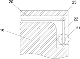
FIG. 5 is a schematic view of the internal structure of the L-shaped groove of the present invention.
In the figure: 1. a chain plate; 2. a bump; 3. a horizontal axis; 4. a bearing; 5. a card slot; 6. a placement groove; 7. a limiting rod; 8. a limiting plate; 9. pushing the plate; 10. a concentration box; 11. a partition plate; 12. collecting a first tank; 13. a limiting column; 14. a chute; 15. placing the plate; 16. a fixing plate; 17. fixing grooves; 18. a cross bar; 19. a clamping block; 20. an L-shaped groove; 21. a gear; 22. a vertical rod; 23. a cross bar.
Detailed Description
The technical solutions in the embodiments of the present invention will be clearly and completely described below with reference to the drawings in the embodiments of the present invention, and it is obvious that the described embodiments are only a part of the embodiments of the present invention, and not all of the embodiments. All other embodiments, which can be derived by a person skilled in the art from the embodiments given herein without making any creative effort, shall fall within the protection scope of the present invention.
Referring to fig. 1-5, the present invention provides a technical solution: a feeding device for fastener production comprises a chain plate 1 and a fixing plate 16, wherein two ends of the chain plate 1 are respectively provided with a lug 2, two sides of each lug 2 are respectively provided with a transverse shaft 3, the transverse shaft 3 is sleeved with a bearing 4, the outer side surface of the bearing 4 is provided with a clamping groove 5, the upper end of the chain plate 1 is provided with a placing groove 6, a limiting rod 7 is arranged between the front end and the rear end of the placing groove 6 and close to the side wall, a limiting plate 8 is arranged between the front end and the rear end of the placing groove 6 and close to the middle position, two groups of limiting rods 7 are sleeved with a push plate 9, a concentration box 10 is arranged between the rear end of the push plate 9 and the side wall of the placing groove 6, the surface of each limiting rod 7 is wound with a limiting spring, the push plate 9 is movably arranged at the bottom end of the placing groove 6 through the limiting spring matched with the limiting, a partition plate 11 is arranged between the side walls of the concentration box 10 near the middle position, the partition plate 11 divides the concentration box 10 into a first collection groove 12 and a second collection groove, a plurality of groups of limiting columns 13 are arranged at the bottom end inside the first collection groove 12, two groups of sliding grooves 14 are respectively arranged on the right side wall of the partition plate 11 and the right side wall inside the concentration box 10, a placing plate 15 is arranged between the partition plate 11 and the concentration box 10, the plurality of groups of limiting columns 13 are arranged in parallel, a plurality of groups of hexagonal clamping holes are arranged at the upper end of the placing plate 15, sliding blocks are arranged inside the sliding grooves 14, the placing plate 15 is movably arranged inside the second collection groove by matching the sliding blocks with the sliding blocks through the sliding grooves 14, the ring-shaped fastener raw material is sleeved on the plurality of groups of limiting columns 13, the column-shaped fastener raw material is arranged in clamping holes arranged on the placing plate 15, different types of fastener raw materials can be distributed, then, the concentration box 10 is arranged in the placing groove 6 through the matching of the limiting groove and the limiting plate 8, the limiting spring is matched with the limiting rod 7 to enable the push plate 9 to move backwards, the concentration box 10 can be clamped, and the concentration box is prevented from falling due to vibration when moving in the device;
the front end of the fixed plate 16 is provided with a fixed groove 17 in a penetrating way near the two sides, the upper end of the fixed plate 16 is provided with a cross rod 18 in a penetrating way near the two sides, the bottom end of the cross rod 18 is provided with a clamping block 19, the fixed plate 16 is movably arranged with a cross shaft 3 by matching the bearing 4 through the fixed groove 17, a plurality of groups of balls are arranged inside the bearing 4, the surface of the cross rod 18 is sleeved with a reset spring, the upper end of the reset spring is fixedly connected with the side wall of the fixed groove 17, the bottom end of the reset spring is fixedly connected with the upper end of the clamping block 19, the clamping block 19 is matched with the clamping groove 5, the position near the bottom inside of the fixed plate 16 is provided with an L-shaped groove 20, the side wall of the L-shaped groove 20 is provided with a gear 21 in a penetrating way, the upper end of the gear 21 is provided with, the left end of a cross rod 23 is contacted with the side surface of the lug 2, a fixing plate 16 is movably arranged at two sides of the lug 2 by matching a fixing groove 17 with a cross shaft 3, wherein a bearing 4 is arranged between the side wall of the cross shaft 3 and the side wall of the fixing groove 17, the fixing plate 16 is matched with the bearing 4 by the fixing groove 17 and rotates around the cross shaft 3, so that the included angle between the fixing plate 16 and the chain plate 1 can be adjusted, then a fixture block 19 is moved downwards to the inside of a clamping groove 5 by matching a reset spring with a cross rod 18, the fixing plate 16 is well limited, so that the fixing plate can be well arranged together with the chain plate 1, the fixing plate 16 is prevented from sliding off in the using process, the device is prevented from being accidentally damaged, the transportation of a fastener is influenced, a plurality of groups of chain plates 1 are connected together by repeating the operations, when one chain plate, the cross rod 23 can move leftwards in the L-shaped groove 20 through the vertical rod 22 matched with the first rotating shaft, wherein the left end of the cross rod 23 is tightly attached to the lug 2, so that the fixing plate 16 is pushed to move rightwards along the surface of the bearing 4, the fixing plate 16 is separated from the chain plate 1, and a worker can replace the damaged chain plate 1 conveniently.
The working principle is as follows: for the feeding device for producing the fasteners, firstly, a worker enables a fixing plate 16 to be movably arranged on two sides of a convex block 2 by matching a fixing groove 17 with a cross shaft 3, wherein a bearing 4 is arranged between the side wall of the cross shaft 3 and the side wall of the fixing groove 17, the fixing plate 16 rotates around the cross shaft 3 by matching the fixing groove 17 with the bearing 4, and then an included angle between the fixing plate 16 and a chain plate 1 can be adjusted, a reset spring enables a clamping block 19 to move downwards to the inside of a clamping groove 5 through a cross rod 18, the fixing plate 16 is well limited, so that the fixing plate can be well arranged together with the chain plate 1, the fixing plate 16 is prevented from sliding off in the using process, the device is accidentally damaged, the transportation of the fasteners is influenced, the groups of chain plates 1 are connected together by repeating the operations, the groups of chain plates 1 can be, when the device is used and a certain chain plate 1 is damaged, the traditional device needs to replace all the chain plates 1, which wastes much expenses and greatly wastes working time, and the connection between the chain plates 1 is tight and is not easy to replace, the clamping block 19 can be pulled out from the inside of the clamping groove 5 by moving the cross rod 18 upwards, then the cross rod 23 can move leftwards inside the L-shaped groove 20 by matching with the rotating shaft I through rotating the gear 21, wherein the left end of the cross rod 23 is tightly attached to the side wall of the lug 2, so as to push the fixing plate 16 to move rightwards along the surface of the bearing 4, so that the fixing plate 16 is separated from the chain plates 1, the damaged chain plates 1 can be conveniently replaced by a worker, the worker can arrange different types of original materials of fasteners mixed together more orderly by sleeving the ring-shaped original materials of the fasteners on the groups of limiting columns 13 and arranging the original materials of the column-shaped fasteners in the clamping holes formed in the placing, convenient to the staff takes, wherein can take out placing plate 15 through 14 cooperation sliders of spout, and then can take off all cylindricality fasteners simultaneously, later set up concentrated case 10 inside standing groove 6 through spacing groove cooperation limiting plate 8, wherein spacing spring cooperation gag lever post 7 makes push pedal 9 remove backward, make its and the laminating of concentrated case 10 lateral wall, thereby can press from both sides tight concentrated case 10, wherein concentrated case 10 passes through spacing groove cooperation limiting plate 8, can play limiting displacement well to it, prevent at the inside bottom surface slip of standing groove 6, thereby can make concentrated case 10 stability when removing in the device better, be convenient for transport the fastener raw materials.
Although embodiments of the present invention have been shown and described, it will be appreciated by those skilled in the art that changes, modifications, substitutions and alterations can be made in these embodiments without departing from the principles and spirit of the invention, the scope of which is defined in the appended claims and their equivalents.
Claims (7)
1. The utility model provides a loading attachment is used in fastener production, includes link joint (1) and fixed plate (16), its characterized in that: link joint (1) both ends all are provided with lug (2), lug (2) both sides all are provided with cross axle (3), the cover is equipped with bearing (4) on cross axle (3), draw-in groove (5) have been seted up on bearing (4) lateral surface, standing groove (6) have been seted up to link joint (1) upper end, be close to the lateral wall position and all be provided with gag lever post (7) between both ends around standing groove (6) is inside, be close to intermediate position between both ends around standing groove (6) is provided with limiting plate (8), and is two sets of the cover is equipped with push pedal (9) on gag lever post (7), be provided with concentrated case (10) between push pedal (9) rear end and standing groove (6) lateral wall.
2. The feeding device for producing the fastener according to claim 1, wherein: be provided with baffle (11) between concentrated case (10) lateral wall near the intermediate position, baffle (11) divide into collecting vat one (12) and collecting vat two with concentrated case (10), the inside bottom of collecting vat one (12) is provided with a plurality of groups spacing post (13), two sets of spout (14) have all been seted up to baffle (11) right side wall and concentrated case (10) inside right side wall, be provided with between baffle (11) and concentrated case (10) and place board (15).
3. The feeding device for producing the fastener according to claim 1, wherein: fixed plate (16) front end is close to both sides position and all runs through and has seted up fixed slot (17), fixed plate (16) upper end is close to both sides position and all runs through and is provided with cross rod (18), cross rod (18) bottom is provided with fixture block (19), fixed plate (16) inside is close to the bottom position and has seted up L type groove (20), L type groove (20) lateral wall runs through and is provided with gear (21), gear (21) upper end is close to the border position and sets up montant (22), montant (22) upper end activity is provided with horizontal pole (23).
4. The feeding device for producing the fastener according to claim 1, wherein: fixed plate (16) cooperate bearing (4) and cross axle (3) activity setting through fixed slot (17), bearing (4) inside is provided with a plurality of groups of ball, and cross rod (18) surface cover is equipped with reset spring, and reset spring upper end and fixed slot (17) lateral wall fixed connection, reset spring bottom and fixture block (19) upper end fixed connection, fixture block (19) and draw-in groove (5) mutually support.
5. The feeding device for producing the fastener according to claim 1, wherein: gag lever post (7) surface winding is provided with spacing spring, push pedal (9) set up in standing groove (6) inside bottom through spacing spring cooperation gag lever post (7) activity, the spacing groove has all been seted up to push pedal (9) and collection box (10) bottom, collection box (10) set up inside standing groove (6) through spacing groove cooperation limiting plate (8) activity.
6. A feeding device for fastener production as claimed in claim 2, wherein: the limiting columns (13) are arranged in parallel, the hexagonal clamping holes are formed in the upper end of the placing plate (15), the sliding blocks are arranged inside the sliding grooves (14), and the placing plate (15) is movably arranged inside the concentration groove II through the sliding grooves (14) in a matched mode.
7. A feeding device for fastener production as claimed in claim 3, wherein: be provided with pivot one between horizontal pole (23) and montant (22), be provided with pivot two between montant (22) and gear (21), horizontal pole (23) are removed along L type groove (20) through montant (22) cooperation gear (21) and are moved, horizontal pole (23) left end contacts with lug (2) side.
Priority Applications (1)
| Application Number | Priority Date | Filing Date | Title |
|---|---|---|---|
| CN202010493910.3A CN111620048B (en) | 2020-06-03 | 2020-06-03 | Feeding device is used in fastener production |
Applications Claiming Priority (1)
| Application Number | Priority Date | Filing Date | Title |
|---|---|---|---|
| CN202010493910.3A CN111620048B (en) | 2020-06-03 | 2020-06-03 | Feeding device is used in fastener production |
Publications (2)
| Publication Number | Publication Date |
|---|---|
| CN111620048A true CN111620048A (en) | 2020-09-04 |
| CN111620048B CN111620048B (en) | 2022-06-21 |
Family
ID=72257305
Family Applications (1)
| Application Number | Title | Priority Date | Filing Date |
|---|---|---|---|
| CN202010493910.3A Active CN111620048B (en) | 2020-06-03 | 2020-06-03 | Feeding device is used in fastener production |
Country Status (1)
| Country | Link |
|---|---|
| CN (1) | CN111620048B (en) |
Citations (7)
| Publication number | Priority date | Publication date | Assignee | Title |
|---|---|---|---|---|
| JPS5785715A (en) * | 1980-11-14 | 1982-05-28 | Manabu Hirasawa | Lunch box holder |
| US6991094B2 (en) * | 2002-03-08 | 2006-01-31 | Frost Links, Inc. | Conveyor chain |
| US20080242462A1 (en) * | 2007-03-29 | 2008-10-02 | Flexon Gmbh | side bow conveyor chain with inner and outer chain links |
| CN202848530U (en) * | 2012-07-31 | 2013-04-03 | 俞华 | Precision connecting conveyor |
| CN203006304U (en) * | 2012-12-19 | 2013-06-19 | 杭州东华链条集团有限公司 | Conveying chain |
| CN203995127U (en) * | 2014-08-26 | 2014-12-10 | 深圳市艾雷激光科技有限公司 | The assembly line conveying device of laser marking machine |
| CN207985919U (en) * | 2018-02-10 | 2018-10-19 | 苏州富邦机械链传动制造有限公司 | A kind of Double-row-roller carrier chain of the U-shaped attachment of band |
-
2020
- 2020-06-03 CN CN202010493910.3A patent/CN111620048B/en active Active
Patent Citations (7)
| Publication number | Priority date | Publication date | Assignee | Title |
|---|---|---|---|---|
| JPS5785715A (en) * | 1980-11-14 | 1982-05-28 | Manabu Hirasawa | Lunch box holder |
| US6991094B2 (en) * | 2002-03-08 | 2006-01-31 | Frost Links, Inc. | Conveyor chain |
| US20080242462A1 (en) * | 2007-03-29 | 2008-10-02 | Flexon Gmbh | side bow conveyor chain with inner and outer chain links |
| CN202848530U (en) * | 2012-07-31 | 2013-04-03 | 俞华 | Precision connecting conveyor |
| CN203006304U (en) * | 2012-12-19 | 2013-06-19 | 杭州东华链条集团有限公司 | Conveying chain |
| CN203995127U (en) * | 2014-08-26 | 2014-12-10 | 深圳市艾雷激光科技有限公司 | The assembly line conveying device of laser marking machine |
| CN207985919U (en) * | 2018-02-10 | 2018-10-19 | 苏州富邦机械链传动制造有限公司 | A kind of Double-row-roller carrier chain of the U-shaped attachment of band |
Also Published As
| Publication number | Publication date |
|---|---|
| CN111620048B (en) | 2022-06-21 |
Similar Documents
| Publication | Publication Date | Title |
|---|---|---|
| CN207064973U (en) | A kind of mounting seat of electromechanical engineering equipment | |
| CN111620048B (en) | Feeding device is used in fastener production | |
| CN204726870U (en) | A kind of dismantled and assembled extendible reinforcing bar pushes away puts support | |
| CN207851117U (en) | A kind of new energy car battery production and processing monitor station | |
| CN203737863U (en) | Sheet metal drawing die provided with locating devices | |
| CN206077842U (en) | It is a kind of to cross furnace carrier | |
| CN208985527U (en) | A kind of Mechanical Design Teaching model equipment | |
| CN211090192U (en) | based on L ED paster device for module | |
| CN206685448U (en) | A kind of easy-to-dismount automobile batteries module mounting bracket | |
| CN205290297U (en) | Axle cluster detaching device | |
| CN210050530U (en) | Movable display screen support | |
| CN201760531U (en) | Rotating shaft mechanism of linear machine | |
| CN211629650U (en) | Clamping structure for fixed mounting of electrical equipment | |
| CN202377270U (en) | Press oil cylinder replacement device | |
| CN217002999U (en) | Nonstandard class gear box convenient to dismantle maintenance | |
| CN209810922U (en) | Full-automatic cold rolling pay-off dolly | |
| CN203681615U (en) | Novel corrugated paper bracket | |
| CN202114845U (en) | Die number splitting device | |
| CN111924484A (en) | Automatic printing paper turning machine and paper turning method thereof | |
| CN214558918U (en) | Automatic bolt and nut assembling machine | |
| CN220372594U (en) | Auxiliary dismounting device for tool clamp of stamping equipment | |
| CN215806199U (en) | Gear box convenient to dismantle | |
| CN211994603U (en) | Special frame for frame inserting machine | |
| CN214413413U (en) | Circulating farming frame | |
| CN209637217U (en) | A kind of bindiny mechanism of building template |
Legal Events
| Date | Code | Title | Description |
|---|---|---|---|
| PB01 | Publication | ||
| PB01 | Publication | ||
| SE01 | Entry into force of request for substantive examination | ||
| SE01 | Entry into force of request for substantive examination | ||
| GR01 | Patent grant | ||
| GR01 | Patent grant |